EP0168072A2 - Durchflussregler für Flüssigkeiten und Gase - Google Patents
Durchflussregler für Flüssigkeiten und Gase Download PDFInfo
- Publication number
- EP0168072A2 EP0168072A2 EP85200744A EP85200744A EP0168072A2 EP 0168072 A2 EP0168072 A2 EP 0168072A2 EP 85200744 A EP85200744 A EP 85200744A EP 85200744 A EP85200744 A EP 85200744A EP 0168072 A2 EP0168072 A2 EP 0168072A2
- Authority
- EP
- European Patent Office
- Prior art keywords
- adjustment
- opening
- head
- housing
- disc
- Prior art date
- Legal status (The legal status is an assumption and is not a legal conclusion. Google has not performed a legal analysis and makes no representation as to the accuracy of the status listed.)
- Withdrawn
Links
Images
Classifications
-
- G—PHYSICS
- G05—CONTROLLING; REGULATING
- G05D—SYSTEMS FOR CONTROLLING OR REGULATING NON-ELECTRIC VARIABLES
- G05D7/00—Control of flow
- G05D7/01—Control of flow without auxiliary power
- G05D7/0106—Control of flow without auxiliary power the sensing element being a flexible member, e.g. bellows, diaphragm, capsule
- G05D7/0113—Control of flow without auxiliary power the sensing element being a flexible member, e.g. bellows, diaphragm, capsule the sensing element acting as a valve
Definitions
- the invention relates to a relatively compact, simple and precise flow regulator for liquids or gases, the flow rate of which can be adjusted between relatively low and high values and whose flow rate is substantially constant despite the pressure difference.
- This flow regulator can be applied, for example, to a protection device for water pipes.
- the flow regulator mainly consists of a closed case with supply and discharge openings, a closure placed in the housing between the supply and discharge openings, a disc of adjustment to several passage boreholes of different diameters, which disc has a diameter smaller than the inside diameter of the housing and is placed at a distance from the closure in the part of the housing into which the intake opening opens, a head adjustment with an opening and placed against the adjustment disc, an axis of rotation passing through the closure and intended to obtain a distortion between the adjustment disc and the adjustment head and the adjustment of a borehole selected passage of the adjusting disc with the opening of the adjusting head, a canali evacuation station provided in the axis of rotation for evacuation of the liquid or gas from the opening of the adjustment head towards the evacuation opening of the housing, and an adjustment membrane placed on the adjustment head and between the supply opening of the housing and a space limited by the membrane and the adjustment head into which the opening of the adjustment head opens and a closure opening of the evacuation pipe, which membrane can close partially or fully to keep constant the pressure
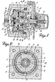
- the flow regulator has a housing 1 with a supply opening 2 and in which are mounted two half-segments 3 at a certain distance from each other so that are formed two evacuation grooves 4 stretching along the longitudinal axis of the housing.
- the housing 1 is closed by means of a cover 5 and a sealing ring 6, which cover has a discharge opening 7 through which the liquid entering via the supply opening 2 and along the spare parts described below is discharged.
- the supply opening 2 is separated from the discharge opening 7 by a closure 8, which is tightened in the cover 5.
- On the closure 8 is fixed an adjusting disc 9 directed towards the supply opening 2 and whose diameter is smaller than the inside diameter of the housing 1.
- This adjustment disc is mounted in such a way on the closure 8 that the liquid or gas entering the housing 1 ⁇ can pass behind this adjustment disc.
- this adjustment disc are provided several passage boreholes 10 of different diameters which each determine a determined flow rate.
- the closure 8 and the adjustment disc 9 passes a rotary axis 11 placed thereon on which is fixed an adjustment button 12 to rotate the axis.
- a sealing ring 13 is placed for the hermetic closure between them of the parts of the housing into which respectively open the supply opening 2 and the discharge opening 7 Likewise, a sealing ring 14 is provided between the abovementioned parts for sealing the shaft 11 in the housing 1, so that water cannot filter out of this housing.
- An elastic ring 15 and a pressure spring 30 exert an axial pressure on the adjustment button 12 and on the axis 11, so that all the constituent parts are pulled against each other.
- the other end of said axis opens onto an adjustment button 16, the inner surface of which adheres to the adjustment disc 9 via an elastic sealing ring 17.
- a similar sealing ring 18 is placed diametrically vis- opposite the ring 17 in order to obtain an equivalent seal and pressure between the adjusting head 16 and the re glage 9.
- This adjustment head 16 is provided with an opening 19 which, when the axis 11 is rotated, is placed in front of one of the passage holes 10 of the adjustment disc 9, and this according to the desired flow rate.
- a scale plate 22 is mounted under the adjustment button 12 on the cover 5.
- a discharge pipe 23 one end of which opens into several openings 24 arranged in radius, whereby said pipe is placed in communication with the discharge opening 7 of the case 1, and the other end is provided with an interchangeable mouth 25 with a closure opening 26.
- an elastic adjustment membrane 27 which surrounds a space 28, into which the closure opening 26 of the mouth 25 opens and which can close this latter opening 26.
- a pressure spring 29 which in the rest position of the flow regulator pushes the diaphragm for adjusting the closure opening 26.
- the liquid or gas entering through the supply opening 2 of the casing 1 goes towards the rear of the adjusting disc 9, enters the passage borehole 10 adjusted, exits by the opening 19 placed opposite, enters the space 28 and leaves the housing 1 through the closing opening 26, the evacuation pipe 23 and the evacuation opening 7 of the housing 1.
Landscapes
- Physics & Mathematics (AREA)
- General Physics & Mathematics (AREA)
- Engineering & Computer Science (AREA)
- Automation & Control Theory (AREA)
- Control Of Fluid Pressure (AREA)
Applications Claiming Priority (2)
| Application Number | Priority Date | Filing Date | Title |
|---|---|---|---|
| BE2/60414A BE899631A (nl) | 1984-05-11 | 1984-05-11 | Debietregelaar voor vloeistoffen of gassen. |
| BE2060414 | 1984-05-11 |
Publications (2)
| Publication Number | Publication Date |
|---|---|
| EP0168072A2 true EP0168072A2 (de) | 1986-01-15 |
| EP0168072A3 EP0168072A3 (de) | 1986-06-04 |
Family
ID=3865690
Family Applications (1)
| Application Number | Title | Priority Date | Filing Date |
|---|---|---|---|
| EP85200744A Withdrawn EP0168072A3 (de) | 1984-05-11 | 1985-05-10 | Durchflussregler für Flüssigkeiten und Gase |
Country Status (1)
| Country | Link |
|---|---|
| EP (1) | EP0168072A3 (de) |
Cited By (2)
| Publication number | Priority date | Publication date | Assignee | Title |
|---|---|---|---|---|
| WO1994021938A1 (en) * | 1993-03-19 | 1994-09-29 | Cambridge Consultants Limited | Flow control valve |
| CN114275878A (zh) * | 2021-12-31 | 2022-04-05 | 杭州凯洁膜分离技术有限公司 | 一种具有保湿功能的外置可拆悬挂式膜生物反应器装置 |
Family Cites Families (5)
| Publication number | Priority date | Publication date | Assignee | Title |
|---|---|---|---|---|
| DE233163C (de) * | ||||
| FR1602211A (de) * | 1968-12-03 | 1970-10-26 | ||
| US3949966A (en) * | 1975-04-30 | 1976-04-13 | Robertshaw Controls Company | Variable constant flow selector valve |
| FR2349084A1 (fr) * | 1976-04-22 | 1977-11-18 | Proengin | Perfectionnements apportes aux regulateurs de debit a membrane |
| GB2049884B (en) * | 1979-05-10 | 1983-02-16 | Redring Electric Ltd | Fluid flow regulator |
-
1985
- 1985-05-10 EP EP85200744A patent/EP0168072A3/de not_active Withdrawn
Cited By (2)
| Publication number | Priority date | Publication date | Assignee | Title |
|---|---|---|---|---|
| WO1994021938A1 (en) * | 1993-03-19 | 1994-09-29 | Cambridge Consultants Limited | Flow control valve |
| CN114275878A (zh) * | 2021-12-31 | 2022-04-05 | 杭州凯洁膜分离技术有限公司 | 一种具有保湿功能的外置可拆悬挂式膜生物反应器装置 |
Also Published As
| Publication number | Publication date |
|---|---|
| EP0168072A3 (de) | 1986-06-04 |
Similar Documents
| Publication | Publication Date | Title |
|---|---|---|
| FR2479396A1 (fr) | Dispositif etrangleur pneumatique | |
| EP1048997A1 (de) | Kartusche für ein Mischventil mit Temperaturbegrenzung | |
| EP0418956A2 (de) | Mischventil mit Kugelhahn | |
| FR2625788A1 (fr) | Vanne mitigeuse thermostatique | |
| FR2652426A1 (fr) | Detendeur de bouteille de gaz. | |
| FR2772452A3 (fr) | Cartouche ou mecanisme destine a un robinet melangeur progressif | |
| FR2731071A1 (fr) | Indicateur de pression differentielle | |
| FR2580054A1 (de) | ||
| FR2545906A1 (fr) | Robinet a soupape a guide pour un reseau de tuyauteries pour liquides | |
| FR2715437A1 (fr) | Dispositif de dosage de fluide, notamment pour gaz d'échappement. | |
| FR2534973A1 (fr) | Vanne de freinage sur echappement | |
| FR2476245A1 (fr) | Soupape d'etranglement dans un circuit de commande | |
| FR2583495A1 (fr) | Dispositif de regulation de debit perfectionne, a pression differentielle | |
| FR2525319A1 (fr) | Robinet mitigeur | |
| EP0168072A3 (de) | Durchflussregler für Flüssigkeiten und Gase | |
| EP0080421A1 (de) | Wassermischbatterie | |
| FR2532034A1 (fr) | Vanne de reglage de debit | |
| FR2830601A1 (fr) | Robinet mitigeur | |
| FR2545626A1 (fr) | Regulateur de pression et separateur pour ce regulateur | |
| EP0006818A2 (de) | Verbesserter hydraulischer Türschliesser | |
| EP0029769B1 (de) | Vergaser mit Starterklappenvorrichtung | |
| FR2789626A1 (fr) | Dispositif d'obturation de trous de passage d'air dans un cylindre, notamment pour les cylindres supports et les manchons de compensation | |
| JPH0953728A (ja) | バルブ | |
| FR2698148A1 (fr) | Mélangeur pour fluides. | |
| EP0128787A1 (de) | Einzylinder- oder Mehrzylinderradialpumpe |
Legal Events
| Date | Code | Title | Description |
|---|---|---|---|
| PUAI | Public reference made under article 153(3) epc to a published international application that has entered the european phase |
Free format text: ORIGINAL CODE: 0009012 |
|
| AK | Designated contracting states |
Designated state(s): DE FR GB NL |
|
| PUAL | Search report despatched |
Free format text: ORIGINAL CODE: 0009013 |
|
| AK | Designated contracting states |
Kind code of ref document: A3 Designated state(s): DE FR GB NL |
|
| STAA | Information on the status of an ep patent application or granted ep patent |
Free format text: STATUS: THE APPLICATION IS DEEMED TO BE WITHDRAWN |
|
| 18D | Application deemed to be withdrawn |
Effective date: 19870204 |