EP0168073A2 - Méthode pour opérer des échanges de chaleur et de matière - Google Patents
Méthode pour opérer des échanges de chaleur et de matière Download PDFInfo
- Publication number
- EP0168073A2 EP0168073A2 EP85200843A EP85200843A EP0168073A2 EP 0168073 A2 EP0168073 A2 EP 0168073A2 EP 85200843 A EP85200843 A EP 85200843A EP 85200843 A EP85200843 A EP 85200843A EP 0168073 A2 EP0168073 A2 EP 0168073A2
- Authority
- EP
- European Patent Office
- Prior art keywords
- streams
- stream
- air
- reagent
- heat
- Prior art date
- Legal status (The legal status is an assumption and is not a legal conclusion. Google has not performed a legal analysis and makes no representation as to the accuracy of the status listed.)
- Granted
Links
- 238000000034 method Methods 0.000 title claims abstract description 67
- 230000008569 process Effects 0.000 claims abstract description 26
- 239000003463 adsorbent Substances 0.000 claims abstract description 20
- 239000000463 material Substances 0.000 claims abstract description 8
- 238000007605 air drying Methods 0.000 claims abstract description 7
- 238000002485 combustion reaction Methods 0.000 claims abstract description 7
- 238000000746 purification Methods 0.000 claims abstract description 7
- 239000007787 solid Substances 0.000 claims abstract description 7
- 238000012546 transfer Methods 0.000 claims abstract description 7
- 238000004821 distillation Methods 0.000 claims abstract description 6
- 239000003153 chemical reaction reagent Substances 0.000 claims description 24
- 239000012530 fluid Substances 0.000 claims description 20
- 238000001179 sorption measurement Methods 0.000 claims description 6
- 238000004378 air conditioning Methods 0.000 claims description 2
- 239000007788 liquid Substances 0.000 abstract description 3
- QVGXLLKOCUKJST-UHFFFAOYSA-N atomic oxygen Chemical compound [O] QVGXLLKOCUKJST-UHFFFAOYSA-N 0.000 description 21
- 229910052760 oxygen Inorganic materials 0.000 description 21
- 239000001301 oxygen Substances 0.000 description 21
- 238000000926 separation method Methods 0.000 description 16
- IJGRMHOSHXDMSA-UHFFFAOYSA-N Atomic nitrogen Chemical compound N#N IJGRMHOSHXDMSA-UHFFFAOYSA-N 0.000 description 14
- 239000011159 matrix material Substances 0.000 description 14
- 239000000203 mixture Substances 0.000 description 13
- QGZKDVFQNNGYKY-UHFFFAOYSA-N Ammonia Chemical compound N QGZKDVFQNNGYKY-UHFFFAOYSA-N 0.000 description 12
- 238000004519 manufacturing process Methods 0.000 description 9
- 229910052757 nitrogen Inorganic materials 0.000 description 7
- 229910021529 ammonia Inorganic materials 0.000 description 6
- 238000001816 cooling Methods 0.000 description 5
- 238000011084 recovery Methods 0.000 description 5
- OKTJSMMVPCPJKN-UHFFFAOYSA-N Carbon Chemical compound [C] OKTJSMMVPCPJKN-UHFFFAOYSA-N 0.000 description 4
- 230000008901 benefit Effects 0.000 description 4
- 239000000470 constituent Substances 0.000 description 4
- 238000001035 drying Methods 0.000 description 4
- 239000007789 gas Substances 0.000 description 4
- 239000000376 reactant Substances 0.000 description 4
- 230000009286 beneficial effect Effects 0.000 description 3
- 238000007796 conventional method Methods 0.000 description 3
- 230000000694 effects Effects 0.000 description 3
- 238000010438 heat treatment Methods 0.000 description 3
- CURLTUGMZLYLDI-UHFFFAOYSA-N Carbon dioxide Chemical compound O=C=O CURLTUGMZLYLDI-UHFFFAOYSA-N 0.000 description 2
- MYMOFIZGZYHOMD-UHFFFAOYSA-N Dioxygen Chemical compound O=O MYMOFIZGZYHOMD-UHFFFAOYSA-N 0.000 description 2
- 229910052799 carbon Inorganic materials 0.000 description 2
- 239000006229 carbon black Substances 0.000 description 2
- 230000006835 compression Effects 0.000 description 2
- 238000007906 compression Methods 0.000 description 2
- 239000003546 flue gas Substances 0.000 description 2
- 239000012535 impurity Substances 0.000 description 2
- 239000000047 product Substances 0.000 description 2
- 238000013022 venting Methods 0.000 description 2
- 239000004215 Carbon black (E152) Substances 0.000 description 1
- UFHFLCQGNIYNRP-UHFFFAOYSA-N Hydrogen Chemical compound [H][H] UFHFLCQGNIYNRP-UHFFFAOYSA-N 0.000 description 1
- VYPSYNLAJGMNEJ-UHFFFAOYSA-N Silicium dioxide Chemical compound O=[Si]=O VYPSYNLAJGMNEJ-UHFFFAOYSA-N 0.000 description 1
- 229920002472 Starch Polymers 0.000 description 1
- PNEYBMLMFCGWSK-UHFFFAOYSA-N aluminium oxide Inorganic materials [O-2].[O-2].[O-2].[Al+3].[Al+3] PNEYBMLMFCGWSK-UHFFFAOYSA-N 0.000 description 1
- 230000015572 biosynthetic process Effects 0.000 description 1
- 239000006227 byproduct Substances 0.000 description 1
- 229910002092 carbon dioxide Inorganic materials 0.000 description 1
- 239000001569 carbon dioxide Substances 0.000 description 1
- 238000001311 chemical methods and process Methods 0.000 description 1
- 150000001875 compounds Chemical class 0.000 description 1
- 230000001627 detrimental effect Effects 0.000 description 1
- 238000005265 energy consumption Methods 0.000 description 1
- 239000003344 environmental pollutant Substances 0.000 description 1
- 239000000446 fuel Substances 0.000 description 1
- 238000007429 general method Methods 0.000 description 1
- 229930195733 hydrocarbon Natural products 0.000 description 1
- 150000002430 hydrocarbons Chemical class 0.000 description 1
- 239000001257 hydrogen Substances 0.000 description 1
- 229910052739 hydrogen Inorganic materials 0.000 description 1
- 230000006872 improvement Effects 0.000 description 1
- 239000011261 inert gas Substances 0.000 description 1
- 230000010354 integration Effects 0.000 description 1
- 230000016507 interphase Effects 0.000 description 1
- 239000002184 metal Substances 0.000 description 1
- 238000012986 modification Methods 0.000 description 1
- 230000004048 modification Effects 0.000 description 1
- 239000002808 molecular sieve Substances 0.000 description 1
- 150000002894 organic compounds Chemical class 0.000 description 1
- 231100000719 pollutant Toxicity 0.000 description 1
- 229920000642 polymer Polymers 0.000 description 1
- 239000000843 powder Substances 0.000 description 1
- 238000002360 preparation method Methods 0.000 description 1
- 238000010926 purge Methods 0.000 description 1
- 230000003134 recirculating effect Effects 0.000 description 1
- 238000002407 reforming Methods 0.000 description 1
- 238000012552 review Methods 0.000 description 1
- 239000000741 silica gel Substances 0.000 description 1
- 229910002027 silica gel Inorganic materials 0.000 description 1
- URGAHOPLAPQHLN-UHFFFAOYSA-N sodium aluminosilicate Chemical compound [Na+].[Al+3].[O-][Si]([O-])=O.[O-][Si]([O-])=O URGAHOPLAPQHLN-UHFFFAOYSA-N 0.000 description 1
- 235000019698 starch Nutrition 0.000 description 1
- 239000000126 substance Substances 0.000 description 1
- 235000000346 sugar Nutrition 0.000 description 1
- 150000008163 sugars Chemical class 0.000 description 1
- 229910052717 sulfur Inorganic materials 0.000 description 1
- 230000001360 synchronised effect Effects 0.000 description 1
- 238000003786 synthesis reaction Methods 0.000 description 1
- 238000010977 unit operation Methods 0.000 description 1
- 239000002699 waste material Substances 0.000 description 1
- XLYOFNOQVPJJNP-UHFFFAOYSA-N water Substances O XLYOFNOQVPJJNP-UHFFFAOYSA-N 0.000 description 1
- 239000010457 zeolite Substances 0.000 description 1
Images


Classifications
-
- B—PERFORMING OPERATIONS; TRANSPORTING
- B01—PHYSICAL OR CHEMICAL PROCESSES OR APPARATUS IN GENERAL
- B01D—SEPARATION
- B01D53/00—Separation of gases or vapours; Recovering vapours of volatile solvents from gases; Chemical or biological purification of waste gases, e.g. engine exhaust gases, smoke, fumes, flue gases, aerosols
- B01D53/02—Separation of gases or vapours; Recovering vapours of volatile solvents from gases; Chemical or biological purification of waste gases, e.g. engine exhaust gases, smoke, fumes, flue gases, aerosols by adsorption, e.g. preparative gas chromatography
- B01D53/06—Separation of gases or vapours; Recovering vapours of volatile solvents from gases; Chemical or biological purification of waste gases, e.g. engine exhaust gases, smoke, fumes, flue gases, aerosols by adsorption, e.g. preparative gas chromatography with moving adsorbents, e.g. rotating beds
- B01D53/08—Separation of gases or vapours; Recovering vapours of volatile solvents from gases; Chemical or biological purification of waste gases, e.g. engine exhaust gases, smoke, fumes, flue gases, aerosols by adsorption, e.g. preparative gas chromatography with moving adsorbents, e.g. rotating beds according to the "moving bed" method
-
- B—PERFORMING OPERATIONS; TRANSPORTING
- B01—PHYSICAL OR CHEMICAL PROCESSES OR APPARATUS IN GENERAL
- B01D—SEPARATION
- B01D53/00—Separation of gases or vapours; Recovering vapours of volatile solvents from gases; Chemical or biological purification of waste gases, e.g. engine exhaust gases, smoke, fumes, flue gases, aerosols
- B01D53/02—Separation of gases or vapours; Recovering vapours of volatile solvents from gases; Chemical or biological purification of waste gases, e.g. engine exhaust gases, smoke, fumes, flue gases, aerosols by adsorption, e.g. preparative gas chromatography
- B01D53/04—Separation of gases or vapours; Recovering vapours of volatile solvents from gases; Chemical or biological purification of waste gases, e.g. engine exhaust gases, smoke, fumes, flue gases, aerosols by adsorption, e.g. preparative gas chromatography with stationary adsorbents
-
- B—PERFORMING OPERATIONS; TRANSPORTING
- B01—PHYSICAL OR CHEMICAL PROCESSES OR APPARATUS IN GENERAL
- B01D—SEPARATION
- B01D53/00—Separation of gases or vapours; Recovering vapours of volatile solvents from gases; Chemical or biological purification of waste gases, e.g. engine exhaust gases, smoke, fumes, flue gases, aerosols
- B01D53/26—Drying gases or vapours
- B01D53/261—Drying gases or vapours by adsorption
-
- F—MECHANICAL ENGINEERING; LIGHTING; HEATING; WEAPONS; BLASTING
- F24—HEATING; RANGES; VENTILATING
- F24F—AIR-CONDITIONING; AIR-HUMIDIFICATION; VENTILATION; USE OF AIR CURRENTS FOR SCREENING
- F24F12/00—Use of energy recovery systems in air conditioning, ventilation or screening
- F24F12/001—Use of energy recovery systems in air conditioning, ventilation or screening with heat-exchange between supplied and exhausted air
-
- F—MECHANICAL ENGINEERING; LIGHTING; HEATING; WEAPONS; BLASTING
- F24—HEATING; RANGES; VENTILATING
- F24F—AIR-CONDITIONING; AIR-HUMIDIFICATION; VENTILATION; USE OF AIR CURRENTS FOR SCREENING
- F24F3/00—Air-conditioning systems in which conditioned primary air is supplied from one or more central stations to distributing units in the rooms or spaces where it may receive secondary treatment; Apparatus specially designed for such systems
- F24F3/12—Air-conditioning systems in which conditioned primary air is supplied from one or more central stations to distributing units in the rooms or spaces where it may receive secondary treatment; Apparatus specially designed for such systems characterised by the treatment of the air otherwise than by heating and cooling
- F24F3/14—Air-conditioning systems in which conditioned primary air is supplied from one or more central stations to distributing units in the rooms or spaces where it may receive secondary treatment; Apparatus specially designed for such systems characterised by the treatment of the air otherwise than by heating and cooling by humidification; by dehumidification
- F24F3/1411—Air-conditioning systems in which conditioned primary air is supplied from one or more central stations to distributing units in the rooms or spaces where it may receive secondary treatment; Apparatus specially designed for such systems characterised by the treatment of the air otherwise than by heating and cooling by humidification; by dehumidification by absorbing or adsorbing water, e.g. using an hygroscopic desiccant
-
- F—MECHANICAL ENGINEERING; LIGHTING; HEATING; WEAPONS; BLASTING
- F24—HEATING; RANGES; VENTILATING
- F24F—AIR-CONDITIONING; AIR-HUMIDIFICATION; VENTILATION; USE OF AIR CURRENTS FOR SCREENING
- F24F3/00—Air-conditioning systems in which conditioned primary air is supplied from one or more central stations to distributing units in the rooms or spaces where it may receive secondary treatment; Apparatus specially designed for such systems
- F24F3/12—Air-conditioning systems in which conditioned primary air is supplied from one or more central stations to distributing units in the rooms or spaces where it may receive secondary treatment; Apparatus specially designed for such systems characterised by the treatment of the air otherwise than by heating and cooling
- F24F3/14—Air-conditioning systems in which conditioned primary air is supplied from one or more central stations to distributing units in the rooms or spaces where it may receive secondary treatment; Apparatus specially designed for such systems characterised by the treatment of the air otherwise than by heating and cooling by humidification; by dehumidification
- F24F3/1411—Air-conditioning systems in which conditioned primary air is supplied from one or more central stations to distributing units in the rooms or spaces where it may receive secondary treatment; Apparatus specially designed for such systems characterised by the treatment of the air otherwise than by heating and cooling by humidification; by dehumidification by absorbing or adsorbing water, e.g. using an hygroscopic desiccant
- F24F3/1429—Air-conditioning systems in which conditioned primary air is supplied from one or more central stations to distributing units in the rooms or spaces where it may receive secondary treatment; Apparatus specially designed for such systems characterised by the treatment of the air otherwise than by heating and cooling by humidification; by dehumidification by absorbing or adsorbing water, e.g. using an hygroscopic desiccant alternatively operating a heat exchanger in an absorbing/adsorbing mode and a heat exchanger in a regeneration mode
-
- B—PERFORMING OPERATIONS; TRANSPORTING
- B01—PHYSICAL OR CHEMICAL PROCESSES OR APPARATUS IN GENERAL
- B01D—SEPARATION
- B01D2259/00—Type of treatment
- B01D2259/40—Further details for adsorption processes and devices
- B01D2259/402—Further details for adsorption processes and devices using two beds
-
- Y—GENERAL TAGGING OF NEW TECHNOLOGICAL DEVELOPMENTS; GENERAL TAGGING OF CROSS-SECTIONAL TECHNOLOGIES SPANNING OVER SEVERAL SECTIONS OF THE IPC; TECHNICAL SUBJECTS COVERED BY FORMER USPC CROSS-REFERENCE ART COLLECTIONS [XRACs] AND DIGESTS
- Y02—TECHNOLOGIES OR APPLICATIONS FOR MITIGATION OR ADAPTATION AGAINST CLIMATE CHANGE
- Y02B—CLIMATE CHANGE MITIGATION TECHNOLOGIES RELATED TO BUILDINGS, e.g. HOUSING, HOUSE APPLIANCES OR RELATED END-USER APPLICATIONS
- Y02B30/00—Energy efficient heating, ventilation or air conditioning [HVAC]
- Y02B30/56—Heat recovery units
-
- Y—GENERAL TAGGING OF NEW TECHNOLOGICAL DEVELOPMENTS; GENERAL TAGGING OF CROSS-SECTIONAL TECHNOLOGIES SPANNING OVER SEVERAL SECTIONS OF THE IPC; TECHNICAL SUBJECTS COVERED BY FORMER USPC CROSS-REFERENCE ART COLLECTIONS [XRACs] AND DIGESTS
- Y10—TECHNICAL SUBJECTS COVERED BY FORMER USPC
- Y10S—TECHNICAL SUBJECTS COVERED BY FORMER USPC CROSS-REFERENCE ART COLLECTIONS [XRACs] AND DIGESTS
- Y10S62/00—Refrigeration
- Y10S62/902—Apparatus
- Y10S62/908—Filter or absorber
Definitions
- the present invention relates to a method for carrying out heat and mass exchange operations. More particularly, the invention relates to an improved method for carrying out heat and mass exchange operations which involves significant decrease of energy required for their performance.
- Mass exchange between two phases is of particular importance largely because it is involved in most separation processes, as for example in the recovery of a pure product from a mixture. Most practical schemes are based on the fact that concentrations of two phases in equilibrium with each other are quite different. Any method of contacting two phases which results in the selective interphase transport of one of the constituents can form the basis of a separation process..7he selectivity can be the result of different equilibrium composition for the different species or it may be due to different rates of transport of the several constituents. Thermodynamic work potential of several kinds may serve to implement mass exchange. In electrochemical processes, an electrical potential provides the motive force, while in a column for the separation of gaseous isotopes, it is a thermal gradient.
- Heat transfer between a relatively hot body and a relatively cold body is also a well established unit operation that is carried in a variety of devices such as heat exchangers, heat regenerators etc.
- thermodynamic work potential provided by the transfer of heat, whereby the hot input stream is tagged as a heat source and the cold input stream is tagged as a heat sink, to drive the separation process in the desired direction, the entire process occurring in one operation.
- This integration may be remedial both from the point view of energy utilization and by virtue of the compactness of the equipment which would perform two functions simultaneously.
- the preparation of oxygen is made mainly from atmospheric air.
- Most processes based on atmospheric air involve two steps which are distinct even when combined in one piece of equipment: (1) the liquefaction of air (preceded by a purification consisting of moisture, carbon dioxide and other impurities removal) and (2) separation of oxygen from the nitrogen by fractionating the liquid in a distillation column.
- air may be considered a binary mixture, or solution of nitrogen and oxygen.
- Air separation plants often discard away a stream of partly separated air, containing 5 to 10% oxygen, in order to economically balance the simultaneous production requirements for pure oxygen and nitrogen. As all other streams in such a plant, it is originally quite cold, justifying cold recovery prior to its venting to the atmosphere.
- the invention relates to a method for carrying out heat and mass exchange operations in a reactor containing a reagent, between two input streams, each stream containing at least two components and possessing a temperature gradient of at least 30 degrees centigrade and the concentrations of the adsorbable species in the cold and the hot feed streams, being such that the equilibrium concentration of the reagent at the conditions of the cold feed streams be higher than that prevailing at the conditions of the hot feed streams wherein said reagent is capable of retaining preferiantially one component as compared to other component (s) or is inert towards the other component (s), the power of retaining of said reagent being higher at lower temperatures than at high temperatures utilizing the thermodynamic work potential provided by the transfer of heat between said two streams to drive the process in the desired direction, obtaining a stream in which the diluted component becomes more diluted while the concentrated component becomes more concentrated in respect to the input stream.
- the method imparts appreciable savings in energy requirements as well as in mass transfer efficiency for a broad number of processes wherein heat and mass exchange operations are involved, provided that they possess the gradients of temperatures and concentrations within the above mentioned ranges.
- adsorbing reagent S which is capable of adsorbing some of A but it is inert towards B.
- the adsorption power of the adsorbing reagent S towards A is high at low temperatures and low at high temperature.
- the adsorbing reagent S is present in a column through which a hot concentrated mixture is fed at one end (tagged for identification as top) and extracted at the other end (tagged for identification as bottom).
- the adsorbent reagent can be selected from a large groups of known compounds used in the art. Typical reagents include alumina, silica gel, zeolites, various forms of carbon such as charcoals and i carbon black, metal powders, organic compounds such as sugars and starches and various polymers. In particular preferably for the present invention will be an adsorbent reagent whereby the equilibrium conditiornss of the cold feed stream is higher by at least 0.01 g adsorbed species per gram adsorbent than that prevailing at the conditions of the hot feed stream.
- the method according to the present invention can be envisaged to be impolemented in a number of chemical processes, some of them being hereafter enumerated being understood that this enumeration should not be limited thereto.
- the method according to the present invention is characterized by its versatility and various embodiments may be conceived using the principle as described above.
- the operation is carried out in at least one pair of adsorption beds which are thermally insulated from their enclosures.
- the mode of operation was already described under the principle of operation as given above.
- Switching valves are directing the streams alternatingly into and out of each bed in a programmed sequence.
- a variation of the above embodiment would replace the on-off switching valves with a unified flow distributor that would perform the same functions.
- Another variation of this embodiment would redirect the effluents exiting the adsorbent beds during those parts of the cycles that are relatively inefficient either in terms of the heat transferred or in terms of the mass transfer, to be passed from one stream to another or to be reprocessed within the same system or separately processed in a conventional heat exchanger or separated by any other means.
- fluctuation of the temperature or compositions of effluents is detrimental to the system, several pairs of beds may be operated in parallel while phased in time through control means of the flows directions by means of a programmed flow guide or switching valves system.
- a schematic illustration of this embodiment is given in Figure 1.
- the solid matrix is structured such that bulk flow is facilitated in a preferred direction (axial or radial) and inhibited otherwise such as for example by means of axially directed channels.
- each channel in the matrix can act effectively as a separate heat-mass exchanger by itself.
- An overall external enclosure for the matrix might be desirable.
- Two synchronized rotary flow distributors located at both ends of the matrix direct the flow to each channel in a proper sequence such that a single matrix operates as a multitude of adsorber/desorber heat regenerator pairs.
- the resulting effect will be substantially the same as that of embodiment (I), but the effluents conditions are inherently smoothed to steady constant values.
- a schematic illustration of this embodiment is given in Figure 2.
- an adsorbent reagent S in the form of fluid is used, thereby facilitating its movement.
- the system consists of two parallel batteries of fluid - fluid contactors/phase separators stages where the heavy fluid reagent S is circulated between the corresponding stages in the two series while the light fluid streams that are to be processed are fed continuously at opposite ends of their respective battery and flow through consecutive stages until they are withdrawn at the other end of the battery.
- the net effect obtained is almost identical to that obtained in the previous embodiment except that the reagent is circulated only between two phases of operation.
- a schematic illustration of this embodiment is given in Figure 3. This embodiment can also be operated in the same way, when the adsorbent reagent S is in the form of a moving solid bed.
- the devices required for the method according to the present invention are characterized by their simplicity and compactness. Although in principle the method may utilize either solid-fluid or liquid-fluid systems, the latter seems to have the advantage of being inherently continuous and steady in operation. A person skilled in the art after reading the present specification, will appreciate the merits of the invention and will select the proper system depending on the materials properties, conditions and process objectives.
- HME Heat and Mass Exchange
- the general method for its manufacture comprises the following basic operations: (a) compression; (b) cooling; (c) separation of the condensed humidity and (d) drying in an adsorption battery which is mostly periodically regenerated thermally by an external power source or by self purging.
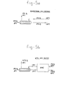
- a schematic flowsheet of the conventional method is given in Figure 4(a).
- Figure 4(b) represents the flowsheet using the HME system according to the present invention.
- the manufacture in this case is much simplified, with improved yield and reduced energy consumption.
- the driving force resulted from the heat generated in the compression step.
- Table 1 The improved results and advantages of the method are summarized i in Table 1, wherein a comparison of conditions prevailing in the conventional plant and these according to the present invention are summarized (the steps and streams refer to the Figures 4(a) and 4(b).
- Air separation plants often discard away a stream of partly separated air (containing about 4% to 10% oxygen) in order to economically balance the simultaneous requirements for pure oxygen and nitrogen. Since the streams in such plants are generally at low temperature, it is more than justified to recover their cold temperature prior to their venting to the atmosphere. Furthermore, an additional recovery of some oxygen present in such streams will be most desirable, thereby raising the oxygen content of the air fed to the plant and facilitating the oxygen production.
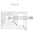
- a schematic flow sheet of a method utilizing the HME system is illustrated in Figure 5.
- HME system provides a low energy air enrichment process to partially separate the undesired constituents from the process air feed stream, obtaining a feed which has a higher oxygen content and a higher temperature than the original stream.
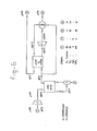
- FIG. 6 A schematic flowsheet with the various conditions and compositions of the streams is presented in Figure 6.
- the method is I based on contacting two gaseous air streams of similar composition close to atmospheric pressure) but one of which is at cryogenic temperature, in a HME system whereby oxygen and some nitrogen are adsorbed from the cold stream while heating it and desorbed into the hot stream while cooling it.
- one stream is enriched in oxygen while the other became lean.
- the necessary cold generation is provided by expansion.
- the HME system compares favourably with conventional existing methods, such as air separation by distillation or by conventional adsorption, both in terms of the compactness of the equipment and its simplicity of operation as well as in terms of the energy required to achieve a same result.
Landscapes
- Chemical & Material Sciences (AREA)
- Engineering & Computer Science (AREA)
- Combustion & Propulsion (AREA)
- Mechanical Engineering (AREA)
- General Engineering & Computer Science (AREA)
- Analytical Chemistry (AREA)
- General Chemical & Material Sciences (AREA)
- Oil, Petroleum & Natural Gas (AREA)
- Chemical Kinetics & Catalysis (AREA)
- Physical Or Chemical Processes And Apparatus (AREA)
- Drying Of Gases (AREA)
- Vaporization, Distillation, Condensation, Sublimation, And Cold Traps (AREA)
- Separation By Low-Temperature Treatments (AREA)
- Separation Of Gases By Adsorption (AREA)
Applications Claiming Priority (2)
| Application Number | Priority Date | Filing Date | Title |
|---|---|---|---|
| IL72058A IL72058A (en) | 1984-06-08 | 1984-06-08 | Method for heat and mass exchange operations |
| IL72058 | 1984-06-08 |
Publications (3)
| Publication Number | Publication Date |
|---|---|
| EP0168073A2 true EP0168073A2 (fr) | 1986-01-15 |
| EP0168073A3 EP0168073A3 (en) | 1987-08-26 |
| EP0168073B1 EP0168073B1 (fr) | 1994-08-24 |
Family
ID=11055123
Family Applications (1)
| Application Number | Title | Priority Date | Filing Date |
|---|---|---|---|
| EP85200843A Expired - Lifetime EP0168073B1 (fr) | 1984-06-08 | 1985-05-24 | Méthode pour opérer des échanges de chaleur et de matière |
Country Status (7)
| Country | Link |
|---|---|
| US (1) | US4661133A (fr) |
| EP (1) | EP0168073B1 (fr) |
| CA (1) | CA1251014A (fr) |
| DE (1) | DE3587911T2 (fr) |
| DK (1) | DK255885A (fr) |
| IL (1) | IL72058A (fr) |
| NO (1) | NO167259C (fr) |
Cited By (1)
| Publication number | Priority date | Publication date | Assignee | Title |
|---|---|---|---|---|
| EP0585174A1 (fr) * | 1992-08-26 | 1994-03-02 | Ram Lavie | Dispositif pour le séchage rapide de l'air comprimé |
Families Citing this family (6)
| Publication number | Priority date | Publication date | Assignee | Title |
|---|---|---|---|---|
| DE3787761T2 (de) * | 1986-06-12 | 1994-02-03 | Ici Plc | Adsorptionsprozess. |
| IL108626A (en) * | 1994-02-13 | 1997-04-15 | Ram Lavie And Technion Researc | Method for the recovery of fugitive organic vapors |
| SG76635A1 (en) * | 1999-03-10 | 2000-11-21 | Japan Pionics | Process and apparatus for recovering ammonia |
| EP1677831A1 (fr) * | 2003-06-05 | 2006-07-12 | Gencell S.A. | Plasmide codant un facteur de croissance des fibroblastes pour le traitement de l'hypercholesterolemie ou du diabete associe a des anomalies angiogeniques |
| US8424515B1 (en) * | 2008-02-07 | 2013-04-23 | Paragon Space Development Corporation | Gas reconditioning systems |
| FR3003183A1 (fr) * | 2013-03-13 | 2014-09-19 | Eblatas | Recycleur a adsorption de co2. |
Family Cites Families (6)
| Publication number | Priority date | Publication date | Assignee | Title |
|---|---|---|---|---|
| DE882541C (de) * | 1951-08-08 | 1953-07-09 | Linde Eismasch Ag | Verfahren und Vorrichtung zur Trennung bzw. Reinigung von Gasgemischen |
| DE1963876C3 (de) * | 1969-12-20 | 1974-08-15 | Roderich W. Dr.-Ing. 6100 Darmstadt-Arheilgen Graeff | Vorrichtung zur selektiven Adsorption von Bestandteilen eines Gasoder Flüssigkeitsgemisches |
| US3839847A (en) * | 1972-07-05 | 1974-10-08 | Hydrocarbon Research Inc | Cryogenic hydrogen adsorption system |
| DE2460515B2 (de) * | 1974-12-20 | 1976-10-28 | ^i/vtaimvti ·«* fvnYtMumg -zur IaU- | Verfahren und vorrichtung zur entfernung von gasfoermigen verunreinigungen aus wasserstoff |
| DE2651906C2 (de) * | 1976-11-13 | 1986-04-03 | Kureha Kagaku Kogyo K.K., Tokio/Tokyo | Vorrichtung zum kontinuierlichen Reinigen eines Abgases |
| JPS576282A (en) * | 1980-06-14 | 1982-01-13 | Kobe Steel Ltd | Air separator |
-
1984
- 1984-06-08 IL IL72058A patent/IL72058A/xx not_active IP Right Cessation
-
1985
- 1985-05-23 US US06/737,229 patent/US4661133A/en not_active Expired - Lifetime
- 1985-05-24 EP EP85200843A patent/EP0168073B1/fr not_active Expired - Lifetime
- 1985-05-24 DE DE3587911T patent/DE3587911T2/de not_active Expired - Fee Related
- 1985-06-06 DK DK255885A patent/DK255885A/da not_active Application Discontinuation
- 1985-06-07 NO NO852303A patent/NO167259C/no unknown
- 1985-06-07 CA CA000483444A patent/CA1251014A/fr not_active Expired
Cited By (1)
| Publication number | Priority date | Publication date | Assignee | Title |
|---|---|---|---|---|
| EP0585174A1 (fr) * | 1992-08-26 | 1994-03-02 | Ram Lavie | Dispositif pour le séchage rapide de l'air comprimé |
Also Published As
| Publication number | Publication date |
|---|---|
| IL72058A (en) | 1988-03-31 |
| CA1251014A (fr) | 1989-03-14 |
| NO167259B (no) | 1991-07-15 |
| DK255885D0 (da) | 1985-06-06 |
| EP0168073A3 (en) | 1987-08-26 |
| DE3587911T2 (de) | 1994-12-15 |
| NO167259C (no) | 1991-10-23 |
| IL72058A0 (en) | 1984-10-31 |
| DE3587911D1 (de) | 1994-09-29 |
| NO852303L (no) | 1985-12-09 |
| EP0168073B1 (fr) | 1994-08-24 |
| DK255885A (da) | 1985-12-09 |
| US4661133A (en) | 1987-04-28 |
Similar Documents
| Publication | Publication Date | Title |
|---|---|---|
| US5944874A (en) | Solid electrolyte ionic conductor systems for the production of high purity nitrogen | |
| EP0212297B1 (fr) | Procédé "haute pression" pour la récupération de soufre d'un courant gazeux contenant du sulfure d'hydrogène | |
| US3150942A (en) | Method of purifying a hydrogen gas stream by passing said gas in series through 13x and 4a or 5a molecular sieves | |
| US3963625A (en) | Ozone generation and recovery system | |
| KR0163351B1 (ko) | 공기 분리법 | |
| EP0460636B1 (fr) | Procédé de préparation d'azote à l'aide de membranes et système | |
| CN102232003A (zh) | 纯化二氧化碳并生成硫酸和硝酸的多步法 | |
| US20080245101A1 (en) | Integrated Method and Installation for Cryogenic Adsorption and Separation for Producing Co2 | |
| WO1999011437A1 (fr) | Procede et appareil de purification de l'argon | |
| KR102084294B1 (ko) | 질산 제조공정을 이용한 반도체용 고순도 일산화질소의 제조방법 및 제조장치 | |
| US5851266A (en) | Hybrid solid electrolyte ionic conductor systems for purifying inert gases | |
| CN119486791B (zh) | 二氧化碳脱水 | |
| US4661133A (en) | Method for heat and mass exchange operations | |
| CN111174530A (zh) | 一种分离提纯氪和氙的方法及装置 | |
| EP0916384A1 (fr) | Production d'oxygène avec des conducteurs ionique à électrolyte solide et purge de vapeur | |
| US2909410A (en) | Recovery of argon from an oxygen containing crude argon mixture | |
| RU2203214C1 (ru) | Способ получения метанола | |
| US3719573A (en) | Periodically reversed gas flow ozone production method and apparatus | |
| US3267645A (en) | Devices for purifying a gas or a gaseous mixture by reversible adsorption | |
| US3389961A (en) | Methods of recovering gases and vapors | |
| JP2001033155A (ja) | 空気分離装置 | |
| CN222634984U (zh) | 一种双塔精馏加氧塔的节能空分装置 | |
| CN220926279U (zh) | 一种氦气提纯系统 | |
| JPH02307506A (ja) | 窒素製造装置用原料空気の精製装置 | |
| SU1460035A1 (ru) | Способ очистки циркул ционного газа синтеза аммиака от инертных примесей |
Legal Events
| Date | Code | Title | Description |
|---|---|---|---|
| PUAI | Public reference made under article 153(3) epc to a published international application that has entered the european phase |
Free format text: ORIGINAL CODE: 0009012 |
|
| AK | Designated contracting states |
Designated state(s): BE DE FR GB IT NL |
|
| PUAL | Search report despatched |
Free format text: ORIGINAL CODE: 0009013 |
|
| AK | Designated contracting states |
Kind code of ref document: A3 Designated state(s): BE DE FR GB IT NL |
|
| 17P | Request for examination filed |
Effective date: 19880216 |
|
| 17Q | First examination report despatched |
Effective date: 19890222 |
|
| GRAA | (expected) grant |
Free format text: ORIGINAL CODE: 0009210 |
|
| AK | Designated contracting states |
Kind code of ref document: B1 Designated state(s): BE DE FR GB IT NL |
|
| REF | Corresponds to: |
Ref document number: 3587911 Country of ref document: DE Date of ref document: 19940929 |
|
| ITF | It: translation for a ep patent filed | ||
| ET | Fr: translation filed | ||
| PLBE | No opposition filed within time limit |
Free format text: ORIGINAL CODE: 0009261 |
|
| STAA | Information on the status of an ep patent application or granted ep patent |
Free format text: STATUS: NO OPPOSITION FILED WITHIN TIME LIMIT |
|
| 26N | No opposition filed | ||
| PGFP | Annual fee paid to national office [announced via postgrant information from national office to epo] |
Ref country code: GB Payment date: 19990521 Year of fee payment: 15 Ref country code: FR Payment date: 19990521 Year of fee payment: 15 |
|
| PGFP | Annual fee paid to national office [announced via postgrant information from national office to epo] |
Ref country code: DE Payment date: 19990525 Year of fee payment: 15 |
|
| PGFP | Annual fee paid to national office [announced via postgrant information from national office to epo] |
Ref country code: NL Payment date: 19990527 Year of fee payment: 15 |
|
| PGFP | Annual fee paid to national office [announced via postgrant information from national office to epo] |
Ref country code: BE Payment date: 19990614 Year of fee payment: 15 |
|
| PG25 | Lapsed in a contracting state [announced via postgrant information from national office to epo] |
Ref country code: GB Free format text: LAPSE BECAUSE OF NON-PAYMENT OF DUE FEES Effective date: 20000524 |
|
| PG25 | Lapsed in a contracting state [announced via postgrant information from national office to epo] |
Ref country code: BE Free format text: LAPSE BECAUSE OF NON-PAYMENT OF DUE FEES Effective date: 20000531 |
|
| BERE | Be: lapsed |
Owner name: TECHNION RESEARCH & DEVELOPMENT FOUNDATION LTD Effective date: 20000531 Owner name: LAVIE RAM Effective date: 20000531 |
|
| PG25 | Lapsed in a contracting state [announced via postgrant information from national office to epo] |
Ref country code: NL Free format text: LAPSE BECAUSE OF NON-PAYMENT OF DUE FEES Effective date: 20001201 |
|
| GBPC | Gb: european patent ceased through non-payment of renewal fee |
Effective date: 20000524 |
|
| PG25 | Lapsed in a contracting state [announced via postgrant information from national office to epo] |
Ref country code: FR Free format text: LAPSE BECAUSE OF NON-PAYMENT OF DUE FEES Effective date: 20010131 |
|
| NLV4 | Nl: lapsed or anulled due to non-payment of the annual fee |
Effective date: 20001201 |
|
| PG25 | Lapsed in a contracting state [announced via postgrant information from national office to epo] |
Ref country code: DE Free format text: LAPSE BECAUSE OF NON-PAYMENT OF DUE FEES Effective date: 20010301 |
|
| REG | Reference to a national code |
Ref country code: FR Ref legal event code: ST |
|
| APAH | Appeal reference modified |
Free format text: ORIGINAL CODE: EPIDOSCREFNO |