EP0168079A1 - Fernsehbildaufnahmeröhre - Google Patents
Fernsehbildaufnahmeröhre Download PDFInfo
- Publication number
- EP0168079A1 EP0168079A1 EP85200886A EP85200886A EP0168079A1 EP 0168079 A1 EP0168079 A1 EP 0168079A1 EP 85200886 A EP85200886 A EP 85200886A EP 85200886 A EP85200886 A EP 85200886A EP 0168079 A1 EP0168079 A1 EP 0168079A1
- Authority
- EP
- European Patent Office
- Prior art keywords
- anode
- cathode
- axis
- electrode
- electron beam
- Prior art date
- Legal status (The legal status is an assumption and is not a legal conclusion. Google has not performed a legal analysis and makes no representation as to the accuracy of the status listed.)
- Withdrawn
Links
Images

Classifications
-
- H—ELECTRICITY
- H01—ELECTRIC ELEMENTS
- H01J—ELECTRIC DISCHARGE TUBES OR DISCHARGE LAMPS
- H01J29/00—Details of cathode-ray tubes or of electron-beam tubes of the types covered by group H01J31/00
- H01J29/46—Arrangements of electrodes and associated parts for generating or controlling the ray or beam, e.g. electron-optical arrangement
- H01J29/48—Electron guns
- H01J29/488—Schematic arrangements of the electrodes for beam forming; Place and form of the elecrodes
-
- H—ELECTRICITY
- H01—ELECTRIC ELEMENTS
- H01J—ELECTRIC DISCHARGE TUBES OR DISCHARGE LAMPS
- H01J29/00—Details of cathode-ray tubes or of electron-beam tubes of the types covered by group H01J31/00
- H01J29/84—Arrangements for removing or diverting unwanted particles, e.g. for negative ions or fringing electrons; Arrangements for velocity or mass selection
Definitions
- the invention relates to a television camera tube comprising in an evacuated envelope a diode electron gun for generating an electron beam, comprising, centred along an axis successively, a cathode having an emissive surface extending substantially at right angles to said axis, an anode having a flat part extending substantially at right angles to the axis and having in its centre a portion which extends in the direction of the cathode and the inner and outer walls of which converge to the axis, said outer wall changing into an apical surface which is substantially parallel to the emissive surface and which has a central aperture.
- Such a television camera tube furthermore comprises a target, for example, consisting of a signal layer having thereon a photoconductive layer for recording the information of the scene to be recorded.
- a target for example, consisting of a signal layer having thereon a photoconductive layer for recording the information of the scene to be recorded.
- a focusing lens for focusing the electron beam on the target and a diaphragm for limiting the electron beam.
- German Patent Application 29 42 063 laid open to public inspection a similar television camera tube is described having a diode electron gun.
- the part of the anode which extends in the direction of the cathode has an outer wall which converges to the axis.
- the inner wall of said part and the remainder of the anode is tubular and extends coaxially around the axis.
- a plate is connected immediately against the anode on the side remote from the cathode and has connected thereto on the cathode side a second gold diaphragm plate having a beam-restricting aperture.
- the distance from the apical surface to said plate according to the Figure shown in the said Patent Application is approximately 1.5 times the distance from the emissive surface to the apical surface.
- Such television camera tube as described hereinbefore are generally known and are sometimes termed vidicons.
- the operation of a vidicon is as follows. Under the influence of the deflection fields, an electron beam of a sufficient current strength scans the free surface of the photoconductive layer of the target according to a given raster and brings said surface point-wise at the potential of the cathode which is termed zero volts. Between two successive scans the potential of each point of the free surface of the photoconductive layer increases under the influence of a positive potential which is applied to the signal layer and under the influence of photoconductivity which is generated in the photoconductive layer by the optical image projected thereon. Each point, or more exactly, each elementary surface element, of the photoconductive layer, together with the underlying signal layer, constitutes a capacitor.
- the charge of said capacitor is periodically completed by the scanning electron beam, for which more charge is required according as more light is incident on the point in question.
- the current which consequently flows through the connection of the signal layer comprises the information of the projected image as a function of time.
- the current strength of the electron beam must be large enough to provide elementary capacitors, which are considerably discharged as a result of large light intensity, with sufficient charge.
- the electrons of the electron beam can no longer reach said point any more. Their speed becomes zero and they are then accelerated in the reverse direction and form the so-called return beam.
- the said return beam also experiences the influence of the deflection fields and scans the surface of the diaphragm facing the photoconductive layer.
- a portion of the secondary electrons generated on the diaphragm has substantially the same kinetic energy as the electrons of the return beam and forms a secondary beam which, together with the original (primary) electron beam, scans the photoconductive layer but in a different place from the primary electron beam because the secondary beam passes through the deflection fields in a different place. As a result of this a disturbing signal is formed which is visible in the picture to be displayed.
- German Patent Application 2230529 (PHN 5726) laid open to public inspection to cause the surface of the diaphragm facing the photoconductive layer, in so far as it is not situated in the immediate proximity of the axis of the tube, to enclose an acute angle with the direction of the said axis.
- the secondary beam has a major direction which is not directed towards the target, because a very large portion of the generated secondary electrons have a direction which is associated in the same manner with the direction of the primary (incident) electrons and with the normal to the surface of the diaphragm as is the case in the reflection of light rays (the angle of incidence is equal to the angle of reflection).
- German published Patent Application 24 34 139 It is suggested to provide a flat diaphragm on the side of the target with a layer of a material having a small coefficient of secondary emission. Chromium is suggested as being particularly suitable since an oxide skin soon forms on it in air. As is known from German Patent Specification 587,386, chromium oxide is a very good suppressor of secondary emission.
- a television camera tube of the kind described in the opening paragraph is characterized according to the invention in that a flat electrode connected electrically to the anode is provided at a distance d from the surface on the side of the anode remote from the cathode, d being between 4 and 25 times the distance from the apical surface to the emissive surface, the said flat electrode having a central aperture which has a diameter which is substantially equal to the diameter of the electron beam at the area of the electrode.
- the central part of the anode on the side remote from the cathode has a wall converging towards the axis as described in United States Patent Specification 4,376,907 or, as described in German Patent Application 29 42 063, consists of two plates in a different location along the axis and of two types of materials, and the return beam is focused on said anode, rapid variations of the number of generated secondary electrons occur due to this irregular design and/or differences in material, as a result of which the observability of the interference signal is inproved.
- the return beam falls on said anode. Since the return beam at the area of said electrode is less focused and the electrode is flat, the number of generated secondary electrons will vary comparatively slowly, so that the signal caused hereby will become visible to a considerably smaller extent.
- the aperture in the flat electrode has such a diameter that the passage of the effective part of the electron beam is not hampered. Said diameter is preferably equal to the diameter of the electron beam at the area of the flat electrode or at most 25% larger.
- the flat electrode is connected to the anode by means of a metal cup-shaped spacing element widening in the direction of the flat electrode, the flat electrode can be incorporated in a simple manner in known diode guns.
- a diode electron gun is disclosed in European Patent Specification No. 0048510 (PHN 9840) which may be considered to be incorporated herein.
- the flat electrode at least on the side remote fran the cathode, consists of a material which has a coefficient of secondary emission which is smaller than 1, the total quantity of secondary electrons generated at the anode is still reduced.
- FIG. 1 is a longitudinal sectional view of a television camera tube according to the invention.
- This tube comprises a cylindrical glass envelope 1 which has a stepped shape obtained by drawing a glass tube which has been softened by heating on a stepped mandril.
- the said tube is sealed by a window 2 on the inside of which the photosensitive target 3 is provided.
- the window 2 lies on the edge 4 which is parallel to the step surfaces 5, 6 and 7 against which a gauze electrode 8, a diaphragm 9 and an anode 10, respectively, bear.
- Wall electrodes which are not shown in the drawing are provided in the usual manner on the inner wall of the cylindrical envelope.
- a cathode support 11 is connected against a first electrode, the anode 10.
- the glass envelope 1 on the side opposite to the window is sealed by means of a cap 12 which is connected against the tube by means of an enamel 13.
- Connection strips 14 which are passed through the enamel seam and also constitute the connections for the anode, the cathode and the cathode filament current extend from the cathode support 11.
- the target 3 usually consists of a photoconductive layer which is provided on a transparent signal plate. However, the target may also comprise a heat-sensitive layer.
- the return beam 100 (indicated by a broken line with arrow) returning from the target passes through the aperture 101 in the diaphragm 9 when the deflection angles of the primary electron beam are small. Because the tapering anode (see Figures 2 and 3) comprises a flat plate-shaped electrode 102 having a central aperture 103, rapid variations in the quantities of generated secondary electrons will not occur due to said flatness and because the return electron beam is not focused there.
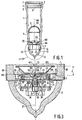
- FIG 2 is an elevation of a part of Figure 1.
- the anode 10 which has a funnel-like aperture 21 lies on the stepped surface 7 which forms a part of the inner wall of the envelope which is at right angles to the axis 20 of the envelope.
- This anode is described elaborately in United States Patent Specification 4,376,907.
- a cathode support is connected against the anode 10.
- Said support comprises a first plate-shaped metal part 22 which makes electrical contact with the anode.
- the second plate-shaped metal part 24 and third plate-shaped metal part 25 situated in one plane are connected against the said first plate-shaped part by means of an electrically insulating sealing glass 23. These two parts constitute the connections for the cathode filament 29 via the contact springs 26, the rods 27 and the metal fins 28.
- a fourth plate-shaped metal part 30 is connected against the said two plate-shaped parts 24 and 25, again by means of an electrically insulating sealing glass.
- the said fourth plate-shaped part comprises strips 31 which extend parallel to the axis 20.
- a metal intermediate plate 32 from which a cathode shank 33 having an emissive surface 37 is suspended by means of bands 34 is connected to the said strips.
- the metal intermediate plate has a central aperture in which a heat reflection screen 35 is provided coaxially around the cathode shank 33.
- Said cathode shank provided in a heat reflection screen forms the subject matter of Netherlands Patent Application 8002343 (PHN 9733) laid open to public inspection which may be considered to be incorporated herein.
- connection strips 36 extend which are passed through the tube via the enamel 13 and constitute the electric connections for the anode, the cathode and the cathode filament current.
- the rods 27 are provided in the intermediate plate 32 by means of a sealing glass 23.
- the anode 10 further comprises a metal cup-shaped spacing element 104 which widens in the direction of the flat electrode 102.
- the electrode 102 comprising aperture 103 is coated, on the side remote from the cathode, with a layer of gold to prevent secondary emission and surface charge as much as possible.
- FIG 3 is a sectional view of the part shown in Figure 2.
- the anode 10 has a flat part 105 which extends at right angles to the axis 20 and has in its centre a portion 106 extending in the direction of the cathode and the inner and outer walls 107, 108 of which converge in the direction of the cathode towards the axis 20.
- the outer wall 108 changes into the apical surface 109 which has a central aperture 110.
- a flat electrode 102 is provided so as to be electrically connected to the anode.
- the distance d is between 4 and 25 times the distance from the apical surface 109 to the emissive surface 37, so that the return beam is not focused on the electrode 102.
- the flat electrode 102 has a central aperture 103 which has a diameter which is approximately equal to the diameter of the electron beam at the area of the electrode 102.
Landscapes
- Image-Pickup Tubes, Image-Amplification Tubes, And Storage Tubes (AREA)
- Electrodes For Cathode-Ray Tubes (AREA)
Applications Claiming Priority (2)
| Application Number | Priority Date | Filing Date | Title |
|---|---|---|---|
| NL8401824 | 1984-06-08 | ||
| NL8401824A NL8401824A (nl) | 1984-06-08 | 1984-06-08 | Televisiekamerabuis. |
Publications (1)
| Publication Number | Publication Date |
|---|---|
| EP0168079A1 true EP0168079A1 (de) | 1986-01-15 |
Family
ID=19844057
Family Applications (1)
| Application Number | Title | Priority Date | Filing Date |
|---|---|---|---|
| EP85200886A Withdrawn EP0168079A1 (de) | 1984-06-08 | 1985-06-06 | Fernsehbildaufnahmeröhre |
Country Status (5)
| Country | Link |
|---|---|
| EP (1) | EP0168079A1 (de) |
| JP (1) | JPS614138A (de) |
| KR (1) | KR860000691A (de) |
| ES (1) | ES8608228A1 (de) |
| NL (1) | NL8401824A (de) |
Cited By (1)
| Publication number | Priority date | Publication date | Assignee | Title |
|---|---|---|---|---|
| EP0338903A1 (de) * | 1988-04-22 | 1989-10-25 | Thomson-Csf | Aufnahmeröhre mit einem Schirm zur Beseitigung von Geisterbildern |
Citations (4)
| Publication number | Priority date | Publication date | Assignee | Title |
|---|---|---|---|---|
| US2708725A (en) * | 1953-03-09 | 1955-05-17 | Loewe Opta Ag | Electrode system for electron-beam valves, in particular for television picture tubes |
| EP0027627A1 (de) * | 1979-10-17 | 1981-04-29 | Heimann GmbH | Elektronenstrahlerzeugersystem für eine Kathodenstrahlröhre |
| US4376907A (en) * | 1979-07-12 | 1983-03-15 | U.S. Philips Corporation | Television camera tube with diode electron gun |
| EP0084915A1 (de) * | 1982-01-25 | 1983-08-03 | Koninklijke Philips Electronics N.V. | Fernsehkameraröhre |
-
1984
- 1984-06-08 NL NL8401824A patent/NL8401824A/nl not_active Application Discontinuation
-
1985
- 1985-06-05 ES ES543926A patent/ES8608228A1/es not_active Expired
- 1985-06-06 EP EP85200886A patent/EP0168079A1/de not_active Withdrawn
- 1985-06-06 JP JP60121601A patent/JPS614138A/ja active Pending
- 1985-06-07 KR KR1019850003968A patent/KR860000691A/ko not_active Withdrawn
Patent Citations (4)
| Publication number | Priority date | Publication date | Assignee | Title |
|---|---|---|---|---|
| US2708725A (en) * | 1953-03-09 | 1955-05-17 | Loewe Opta Ag | Electrode system for electron-beam valves, in particular for television picture tubes |
| US4376907A (en) * | 1979-07-12 | 1983-03-15 | U.S. Philips Corporation | Television camera tube with diode electron gun |
| EP0027627A1 (de) * | 1979-10-17 | 1981-04-29 | Heimann GmbH | Elektronenstrahlerzeugersystem für eine Kathodenstrahlröhre |
| EP0084915A1 (de) * | 1982-01-25 | 1983-08-03 | Koninklijke Philips Electronics N.V. | Fernsehkameraröhre |
Cited By (3)
| Publication number | Priority date | Publication date | Assignee | Title |
|---|---|---|---|---|
| EP0338903A1 (de) * | 1988-04-22 | 1989-10-25 | Thomson-Csf | Aufnahmeröhre mit einem Schirm zur Beseitigung von Geisterbildern |
| FR2630586A1 (fr) * | 1988-04-22 | 1989-10-27 | Thomson Csf | Tube de camera avec ecran de suppression d'image parasite |
| US5218443A (en) * | 1988-04-22 | 1993-06-08 | Thomson-Csf | Television camera tube with spurious image black-out screen |
Also Published As
| Publication number | Publication date |
|---|---|
| ES8608228A1 (es) | 1986-06-01 |
| ES543926A0 (es) | 1986-06-01 |
| JPS614138A (ja) | 1986-01-10 |
| NL8401824A (nl) | 1986-01-02 |
| KR860000691A (ko) | 1986-01-30 |
Similar Documents
| Publication | Publication Date | Title |
|---|---|---|
| US2541374A (en) | Velocity-selection-type pickup tube | |
| CA1135774A (en) | Cathode-ray tube with low anode potential preventing positive ion formation | |
| US2100259A (en) | Television | |
| US2579351A (en) | Isocon pickup tube | |
| US2739258A (en) | System of intensification of x-ray images | |
| US3697795A (en) | Image intensifier tube having a multi-radius photocathode | |
| US3866079A (en) | Television camera tube in which the detrimental effect of the return beam is counteracted | |
| EP0114714B1 (de) | Vorrichtung mit einer Kathodenstrahlröhre mit Elektronenkanone mit niedrigem Rauschen | |
| US3213311A (en) | Electron discharge device | |
| US3474275A (en) | Image tube having a gating and focusing electrode | |
| US2760096A (en) | Television pickup tube | |
| EP0168079A1 (de) | Fernsehbildaufnahmeröhre | |
| US2244466A (en) | Television | |
| US2314648A (en) | Television transmitting and the like system | |
| US3801855A (en) | Television camera tube | |
| US2091862A (en) | Photoelectric image converter | |
| US2619531A (en) | Pickup tube for television and the like | |
| US3300668A (en) | Image converter tube | |
| US4752715A (en) | Television camera tube | |
| EP0072588B1 (de) | Kathodenstrahlröhre | |
| US3688122A (en) | An electrostatic focused electron image device | |
| US4173727A (en) | Electron image device | |
| US2227097A (en) | Electron tube apparatus | |
| US2227092A (en) | Cathode ray tube | |
| US3694686A (en) | Unidirectional double deflection type cathode ray tube |
Legal Events
| Date | Code | Title | Description |
|---|---|---|---|
| PUAI | Public reference made under article 153(3) epc to a published international application that has entered the european phase |
Free format text: ORIGINAL CODE: 0009012 |
|
| AK | Designated contracting states |
Designated state(s): DE FR GB IT |
|
| 17P | Request for examination filed |
Effective date: 19860606 |
|
| STAA | Information on the status of an ep patent application or granted ep patent |
Free format text: STATUS: THE APPLICATION IS DEEMED TO BE WITHDRAWN |
|
| 18D | Application deemed to be withdrawn |
Effective date: 19871231 |
|
| RIN1 | Information on inventor provided before grant (corrected) |
Inventor name: HIMMELBAUER, ERICH EDUARD Inventor name: VAN DEN BERG, JACOB |