EP0168085A1 - Medicotherapeutische Vorrichtung - Google Patents
Medicotherapeutische Vorrichtung Download PDFInfo
- Publication number
- EP0168085A1 EP0168085A1 EP85200934A EP85200934A EP0168085A1 EP 0168085 A1 EP0168085 A1 EP 0168085A1 EP 85200934 A EP85200934 A EP 85200934A EP 85200934 A EP85200934 A EP 85200934A EP 0168085 A1 EP0168085 A1 EP 0168085A1
- Authority
- EP
- European Patent Office
- Prior art keywords
- pressure
- chambers
- chamber
- fluid
- proximal
- Prior art date
- Legal status (The legal status is an assumption and is not a legal conclusion. Google has not performed a legal analysis and makes no representation as to the accuracy of the status listed.)
- Granted
Links
- 239000012530 fluid Substances 0.000 claims abstract description 21
- 230000010349 pulsation Effects 0.000 claims abstract description 19
- 230000007423 decrease Effects 0.000 claims abstract description 9
- 230000003247 decreasing effect Effects 0.000 claims abstract description 6
- 210000004204 blood vessel Anatomy 0.000 claims abstract description 3
- 239000013013 elastic material Substances 0.000 claims description 3
- 230000000737 periodic effect Effects 0.000 claims 2
- 239000008280 blood Substances 0.000 abstract description 6
- 210000004369 blood Anatomy 0.000 abstract description 6
- 210000002683 foot Anatomy 0.000 description 13
- 210000003414 extremity Anatomy 0.000 description 12
- 210000003423 ankle Anatomy 0.000 description 4
- 239000000463 material Substances 0.000 description 4
- 238000005086 pumping Methods 0.000 description 4
- 239000005060 rubber Substances 0.000 description 4
- 239000004033 plastic Substances 0.000 description 3
- 229920003023 plastic Polymers 0.000 description 3
- 238000004891 communication Methods 0.000 description 2
- 239000002184 metal Substances 0.000 description 2
- 229920001875 Ebonite Polymers 0.000 description 1
- 238000004026 adhesive bonding Methods 0.000 description 1
- 230000032683 aging Effects 0.000 description 1
- 230000017531 blood circulation Effects 0.000 description 1
- 230000036770 blood supply Effects 0.000 description 1
- 238000007664 blowing Methods 0.000 description 1
- 210000000481 breast Anatomy 0.000 description 1
- 238000009826 distribution Methods 0.000 description 1
- 230000000694 effects Effects 0.000 description 1
- 239000004744 fabric Substances 0.000 description 1
- 230000002349 favourable effect Effects 0.000 description 1
- 229920002457 flexible plastic Polymers 0.000 description 1
- 239000006260 foam Substances 0.000 description 1
- 239000007788 liquid Substances 0.000 description 1
- 238000000034 method Methods 0.000 description 1
- 210000003205 muscle Anatomy 0.000 description 1
- 230000003387 muscular Effects 0.000 description 1
- 210000002445 nipple Anatomy 0.000 description 1
- 230000000149 penetrating effect Effects 0.000 description 1
- 230000000284 resting effect Effects 0.000 description 1
- 230000008320 venous blood flow Effects 0.000 description 1
- 230000003313 weakening effect Effects 0.000 description 1
- 238000003466 welding Methods 0.000 description 1
Images
Classifications
-
- A—HUMAN NECESSITIES
- A61—MEDICAL OR VETERINARY SCIENCE; HYGIENE
- A61H—PHYSICAL THERAPY APPARATUS, e.g. DEVICES FOR LOCATING OR STIMULATING REFLEX POINTS IN THE BODY; ARTIFICIAL RESPIRATION; MASSAGE; BATHING DEVICES FOR SPECIAL THERAPEUTIC OR HYGIENIC PURPOSES OR SPECIFIC PARTS OF THE BODY
- A61H9/00—Pneumatic or hydraulic massage
- A61H9/005—Pneumatic massage
- A61H9/0078—Pneumatic massage with intermittent or alternately inflated bladders or cuffs
-
- A—HUMAN NECESSITIES
- A61—MEDICAL OR VETERINARY SCIENCE; HYGIENE
- A61H—PHYSICAL THERAPY APPARATUS, e.g. DEVICES FOR LOCATING OR STIMULATING REFLEX POINTS IN THE BODY; ARTIFICIAL RESPIRATION; MASSAGE; BATHING DEVICES FOR SPECIAL THERAPEUTIC OR HYGIENIC PURPOSES OR SPECIFIC PARTS OF THE BODY
- A61H9/00—Pneumatic or hydraulic massage
- A61H9/005—Pneumatic massage
- A61H9/0078—Pneumatic massage with intermittent or alternately inflated bladders or cuffs
- A61H9/0085—Inflated by user's body movement, e.g. ambulatory devices
Definitions
- This invention relates to a device for sustaining the operation of the blood vessels in the human body, at least in part in one of the limbs thereof, with more than one chamber to be positioned in contact with different zones of the body, said chambers being adapted to take up a fluid such as air under pressure and having a flexible wall for transmitting said pressure to the body, with means to subject a fluid in said chambers to a pulsating pressure.
- Chambers, positioned more remotely from the extremity of said human limb are filled from more distal chambers through narrow throttling connections or by check valves opening against a relatively high pressure difference, so that proximal chambers in each pulsation cycle are subjected to a much lower pressure than distal chambers.
- the relief of the proximal chambers takes place through distal chambers through check valves, opening against a much lower pressure difference (and of course in opposite direction) than the check valves used for filling the chambers with the fluid.
- a more proximal chamber is relieved more slowly than a more distal chamber, but by the lower pressure in said more proximal chamber it rapidly reaches a pressure as low as the pressure in such a more distal chamber before the next pressure rise begins.
- the invention aims at improving such devices.
- the operation is not optimal, and moreover that this is to be attributed to the fact that, during the pressure decreasing phase of the pulsations much venous blood flows back immediately to the distal part of the limb, in particular to the lower leg of standing or sitting patients.
- the invention proposes to embody such pulsating means in such a way that, during decrease of the pressure in said chambers, the pressure in one or more more proximal chambers is maintained at a much higher value than the pressure in one or more more distal chambers at least until the next pressure rise occurs.
- At least one more proximal chamber loses its pressure during the relief phase of the pulsations more slowly than at least one more distal chamber, which has a favourable influence as to avoiding such rapid back flow of venous blood.
- the most proximal chamber may be present on part of the human torso, e.g. on breast, shoulder or hip.
- the pulsations may be generated by applying a flexible "pumping chamber" below the foot, which chamber is in fluid communication with one or more pressure chambers in contact with parts of the leg so that a fluid such as air is pumped to said pressure chambers by and from said pumping chamber when placing the foot during walking and that, when lifting the foot, this fluid flows back into said pumping chamber.
- a fluid such as air is pumped to said pressure chambers by and from said pumping chamber when placing the foot during walking and that, when lifting the foot, this fluid flows back into said pumping chamber.
- Such pulsations may be generated with the aid of a pump or pressure vessel and a controlled pulsation device, e.g. as disclosed in the said U.S. patent specifications 4,030,488 and 4,029,087.
- the invention moreover relates to preferred embodiments of said principle.
- Throttling openings for the pressure relief may be present between the different chambers, but they may also lead directly from each chamber to the outside.
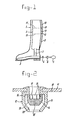
- the device of Fig. 1 is embodied as a boot 1, provided with a number of chambers 3, 8, 9, 10 for pressure pulsations, being permanently or easily detachably mounted in said boot.
- the chambers have flexible fluid-tight walls, which preferably are not elastic or only very little, such as a fabric impregnated and/or covered by a suitable flexible plastics or rubber material. In this case they are mutually connected to a unit 2.
- the boot may have zippers or bootlaces not shown to be easily pulled on and taken off.
- this unit has a flexible chamber 3, extending under the entire surface of the human foot sole or under the greater part thereof.
- a closable connecting nipple 4 serves to keep said unit filled with a fluid such as air, e.g. by the use of a simple hand or foot pump 5 easily connectable thereto and detachable therefran, e.g. as usual for inflating air beds or rubber boats, but it is also possible to fill this unit by blowing by mouth or connection to any source of pressurized air or other gas.
- a meter 6 shows the filling pressure.
- the nippel 4 may be connected at any point to unit 2, e.g. to one side of the sole or higher.
- the chamber 3 is in open fluid connection with a chamber 8 through a flexible duct 7 extending along foot and ankle.
- a chamber 8 there are two further chambers 9 and 10.
- this duct may be embedded in a suitable material such as elastic foam plastic.
- Said chambers 8 to 10 extend along the back side and along part of the sides of the lower leg. There may also be one or more chambers in contact with the upper leg and it is even possible that e.g. a hose connects the upper chamber 10 to a chamber to be applied to the patient at the height of the hip. If desired the duct 7 may be very short and chamber 8 may extend downwardly along the ankle, so that a pulsating pressure may also be exerted on the median or lateral ankle.
- each wall 11 has a flow connection 12 between bordering chambers, indicated in Fig. 1 only diagrammatically by a dash. In Fig. 2 and 3 this connection 12 is shown in detail on a larger scale.
- valve casing 13 is mounted in an opening in each wall 11.
- This casing may be of metal, rather hard rubber or plastics material and it may be mounted by clamping, bonding or vulcanising or any other suitable connection method to wall 11.
- a valve body 14 is freely movable up and down in said casing and consists of metal, rubber or plastics material. At least one of the parts 13 and 14 is made of elastic material of such flexibility that body 14 is introduceable into casing 13. It is also possible to provide casing 13 with a separate part enclosing body 14 after introduction and mountable e.g. by screwing or screws, welding or glueing.
- Valve body 14 has protrusions 15 such as battlements, which in the highest position of body 14 engage a shoulder 16 in casing 13 so as to allow fluid to pass through openings 17 in the battlements. Moreover this body 14 as a relatively narrow bore 18 and a conical outer surface 19 having the same cone angle as a seat 20 in casing 13. Said angle is chosen of such a high value that body 14 leaves said seat 20 upwardly easily and is not clamped thereby.
- Fig. 3 there is small tube 21 of rubber or the like elastic material, bonded, e.g. vulcanised, sealingly in a hole in wall 11.
- This tube 21 is open at its lower end and closed by end wall 22 at its top.
- Above wall 11 it has a longitudinal (vertical) cut 23, so narrow that it is closed (gas tight) if the air pressures to both sides thereof are equal and for all pressure differences with a higher pressure at the outside of this cut.
- a small (throttling) hole 24 penetrating the wall of tube 21 above wall 11.
- chamber 8 When lifting the foot the air tends to flow in the opposite direction, chamber 8 is subjected to a decrease in pressure together with chamber 3 by the increase in volume of the latter.
- the throttling openings 18 (Fig. 2) or 24 (Fig. 3) now form the only flow connection between chambers 8, 9 and 10, so that the pressure in chamber 9 decreases more slowly than in chamber 8 and in chamber 10 the pressure drop is even more slow.
- said pressure drop in chambers 9 and 10 is not only more slow but finally also, until the next pressure rise begins, less in amount, and, for chamber 10, even if desired negligible.
- the chambers 8, 9 and 10 may be relatively thin in a direction perpendicular to the leg, and chamber 3 is chosen at a relatively considerable volume.
- the throttling opening 18 or 24 between chambers 8 and 9 is preferably wider than the same opening between chambers 9 and 10. Thereby, chamber 9 will, during the pressure relief phase, much more rapidly fall in pressure to a pressure, considerably lower than the pressure in chamber 10, for which it is important that the pressure remains high to avoid backflow of venous blood.
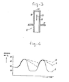
- Fig. 4 shows possible pressure distributions and pressure pulsations in a device according to Fig. 1.
- the pressure in the entire device is e.g. somewhat less than 40 m Hg.
- the pressure in chamber 8 near 4b rises quickly to about the same level.
- the pressure in chamber 9 also rises quickly to about the same value and the thereupon opening check valve body 14 of Fig. 2 or slot 23 of Fig. 3 between chambers 9 and 10 causes chamber 10 to follow almost the same pressure rise.
- the pressures in the chambers 8, 9 and 10 have risen to say about 70 mn Hg.
- the pressure in chambers 3 and 8 drops rapidly, e.g. to about 20 to 25 mm Hg.
- check valve 14 of Fig. 2 drops (closes) as soon as the pressures in the adjacent chambers to both sides thereof are about equal, or as slot 23 closes in this situation, the chambers 8, 9 and 10 are now only in communication by the throttling openings 18 of Fig. 2 or 24 of Fig. 3.
- the pressure in chamber 10 will decrease even less (line of dots and dashes in Fig. 4), e.g. to 55 mm Hg when the next pressure rise begins. Without harm the pressure in chamber 9 may drop to lower values, e.g. by a wider throttling opening 18 or 24.
- the stationary pressure in the device of somewhat below 40 mm Hg is low enough to avoid undesired blood congestion.
- the chambers 9 and 10 might also have a throttling relief opening to the outside for replacing or additional to openings 18 between chambers 8, 9 and 10..
- a throttling relief opening to the outside for replacing or additional to openings 18 between chambers 8, 9 and 10..
- the pressure in more proximal chambers 9 and 10 will then remain lower than in chamber 8, but this may be acceptable, if only the unit 2 is not allowed to remain deflated, e.g. by making chamber 3 elastic in a sense to tend to increase in volume.
- the unit 2 it is possible to use the unit 2 without a surrounding boot, in which case it might be strapped onto the human leg.
- valves as shown in Figs. 2 and 3 there may be simple ball valves as check valves. Particularly in such a case the throttling opening between adjacent chambers may be provided in the separating wall 11 thereof itself, as shown by 18' in Fig. 2.
- each chamber may have its own separate connection to such an external source in which case rises and falls in pressure are controlled, e.g. with the aid of a microprocessor in such a way that one or more more proximal chambers during the pressure fall are less relieved or less rapidly relieved than one or more distal chambers.
- the use of more than three chambers may be deemed preferable, but this is known as such.
- the number of subsequent chambers is of less importance, if only the most proximal chamber satisfies the requirement of the invention about a smaller value of its pressure drop during the relief phase.
Landscapes
- Health & Medical Sciences (AREA)
- Public Health (AREA)
- Epidemiology (AREA)
- Pain & Pain Management (AREA)
- Physical Education & Sports Medicine (AREA)
- Rehabilitation Therapy (AREA)
- Life Sciences & Earth Sciences (AREA)
- Animal Behavior & Ethology (AREA)
- General Health & Medical Sciences (AREA)
- Veterinary Medicine (AREA)
- Massaging Devices (AREA)
Applications Claiming Priority (2)
| Application Number | Priority Date | Filing Date | Title |
|---|---|---|---|
| NL8401873 | 1984-06-13 | ||
| NL8401873A NL8401873A (nl) | 1984-06-13 | 1984-06-13 | Medisch-therapeutische inrichting. |
Publications (2)
| Publication Number | Publication Date |
|---|---|
| EP0168085A1 true EP0168085A1 (de) | 1986-01-15 |
| EP0168085B1 EP0168085B1 (de) | 1988-10-26 |
Family
ID=19844073
Family Applications (1)
| Application Number | Title | Priority Date | Filing Date |
|---|---|---|---|
| EP19850200934 Expired EP0168085B1 (de) | 1984-06-13 | 1985-06-12 | Medicotherapeutische Vorrichtung |
Country Status (3)
| Country | Link |
|---|---|
| EP (1) | EP0168085B1 (de) |
| DE (1) | DE3565772D1 (de) |
| NL (1) | NL8401873A (de) |
Cited By (10)
| Publication number | Priority date | Publication date | Assignee | Title |
|---|---|---|---|---|
| EP0392669A3 (de) * | 1989-04-12 | 1991-05-15 | The Kendall Company | Vorrichtung zum Ausüben von Druck auf ein Körperglied eines Patienten |
| EP0388200A3 (de) * | 1989-03-16 | 1991-05-22 | The Kendall Company | Auf der ganzen Länge kompressible Manschette |
| GB2263405A (en) * | 1992-01-16 | 1993-07-28 | Maher Asad Hamzeh | Ambulatory pneumatic compression device |
| FR2768334A1 (fr) * | 1997-09-15 | 1999-03-19 | Roger Pons | Dispositif de drainage lymphatique ambulatoire |
| EP0805670A4 (de) * | 1995-11-20 | 1999-12-29 | Ibrahim M Ibrahim | Selbstaufblasbarer schuh gegen venenschmerzen |
| DE19935722C1 (de) * | 1999-07-29 | 2001-04-12 | Anne Maria Giebisch | Vorrichtung zur Verbesserung der Venenaktivität |
| US7258676B2 (en) | 2003-06-11 | 2007-08-21 | C-Boot Ltd | Device and method for low pressure compression and valve for use in the system |
| EP3585491A4 (de) * | 2017-02-23 | 2021-06-09 | Brummond, Darren | Objekte und verfahren zur herstellung von kleinen muskelfasern und nerven mithilfe eines in den objekten verteilten fluids |
| EP3903619A1 (de) * | 2020-04-28 | 2021-11-03 | Guangdong Breath Walker Health Technology Co., Ltd. | Aufblasbare massageschuhe |
| CN117100572A (zh) * | 2023-09-05 | 2023-11-24 | 中国人民解放军总医院第四医学中心 | 一种预防静脉曲张的腿部按摩装置 |
Citations (4)
| Publication number | Priority date | Publication date | Assignee | Title |
|---|---|---|---|---|
| US4029087A (en) * | 1975-10-28 | 1977-06-14 | The Kendall Company | Extremity compression device |
| US4345594A (en) * | 1980-09-12 | 1982-08-24 | Institute Of Critical Care Medicine | Closely controllable intravenous injection system |
| NL8201189A (nl) * | 1982-03-23 | 1983-10-17 | Johan Pieter Hulsbergen Hennin | Medisch therapeutische inrichting. |
| US4428396A (en) * | 1978-07-19 | 1984-01-31 | City Tank Corporation | Adjustable valve assembly |
-
1984
- 1984-06-13 NL NL8401873A patent/NL8401873A/nl not_active Application Discontinuation
-
1985
- 1985-06-12 DE DE8585200934T patent/DE3565772D1/de not_active Expired
- 1985-06-12 EP EP19850200934 patent/EP0168085B1/de not_active Expired
Patent Citations (4)
| Publication number | Priority date | Publication date | Assignee | Title |
|---|---|---|---|---|
| US4029087A (en) * | 1975-10-28 | 1977-06-14 | The Kendall Company | Extremity compression device |
| US4428396A (en) * | 1978-07-19 | 1984-01-31 | City Tank Corporation | Adjustable valve assembly |
| US4345594A (en) * | 1980-09-12 | 1982-08-24 | Institute Of Critical Care Medicine | Closely controllable intravenous injection system |
| NL8201189A (nl) * | 1982-03-23 | 1983-10-17 | Johan Pieter Hulsbergen Hennin | Medisch therapeutische inrichting. |
Cited By (14)
| Publication number | Priority date | Publication date | Assignee | Title |
|---|---|---|---|---|
| EP0388200A3 (de) * | 1989-03-16 | 1991-05-22 | The Kendall Company | Auf der ganzen Länge kompressible Manschette |
| EP0392669A3 (de) * | 1989-04-12 | 1991-05-15 | The Kendall Company | Vorrichtung zum Ausüben von Druck auf ein Körperglied eines Patienten |
| AU629293B2 (en) * | 1989-04-12 | 1992-10-01 | Kendall Company, The | Device for applying compressive pressure against a patient's limb |
| GB2263405A (en) * | 1992-01-16 | 1993-07-28 | Maher Asad Hamzeh | Ambulatory pneumatic compression device |
| GB2263405B (en) * | 1992-01-16 | 1996-02-14 | Maher Asad Hamzeh | Ambulatory pneumatic compression device |
| EP0805670A4 (de) * | 1995-11-20 | 1999-12-29 | Ibrahim M Ibrahim | Selbstaufblasbarer schuh gegen venenschmerzen |
| FR2768334A1 (fr) * | 1997-09-15 | 1999-03-19 | Roger Pons | Dispositif de drainage lymphatique ambulatoire |
| DE19935722C1 (de) * | 1999-07-29 | 2001-04-12 | Anne Maria Giebisch | Vorrichtung zur Verbesserung der Venenaktivität |
| US7258676B2 (en) | 2003-06-11 | 2007-08-21 | C-Boot Ltd | Device and method for low pressure compression and valve for use in the system |
| WO2004108051A3 (en) * | 2003-06-11 | 2007-11-29 | Boot Ltd C | Device and method for low pressure compresssion and valve for use in the system |
| EP3585491A4 (de) * | 2017-02-23 | 2021-06-09 | Brummond, Darren | Objekte und verfahren zur herstellung von kleinen muskelfasern und nerven mithilfe eines in den objekten verteilten fluids |
| US11071884B2 (en) | 2017-02-23 | 2021-07-27 | Darren Brummond | Objects and methods for building small muscle fibers and nerves using fluid disposed in the objects |
| EP3903619A1 (de) * | 2020-04-28 | 2021-11-03 | Guangdong Breath Walker Health Technology Co., Ltd. | Aufblasbare massageschuhe |
| CN117100572A (zh) * | 2023-09-05 | 2023-11-24 | 中国人民解放军总医院第四医学中心 | 一种预防静脉曲张的腿部按摩装置 |
Also Published As
| Publication number | Publication date |
|---|---|
| EP0168085B1 (de) | 1988-10-26 |
| NL8401873A (nl) | 1986-01-02 |
| DE3565772D1 (en) | 1988-12-01 |
Similar Documents
| Publication | Publication Date | Title |
|---|---|---|
| US7258676B2 (en) | Device and method for low pressure compression and valve for use in the system | |
| EP0150553B1 (de) | Medizinisches Gerät zur Ausübung einer Pumpwirkung auf die Fusssohle | |
| US5496262A (en) | Therapeutic intermittent compression system with inflatable compartments of differing pressure from a single source | |
| EP0861652B1 (de) | Pneumatische Kompressionseinrichtung sowie Verfahren zur Anwendung auf medizinischem Gebiet | |
| US20010018564A1 (en) | Medical apparatus for facilitating blood circulation in the lower limbs | |
| US6190304B1 (en) | Enhanced intra-aortic balloon assist device | |
| US3720199A (en) | Safety connector for balloon pump | |
| US6468237B1 (en) | Pneumatic pump, housing and methods for medical purposes | |
| JPH0838563A (ja) | 医療用ポンプ装置 | |
| US8585582B2 (en) | Peristaltically inflatable penile prosthetic | |
| EP0168085B1 (de) | Medicotherapeutische Vorrichtung | |
| EP0603186A4 (de) | Herzmassagevorrichtung. | |
| JPH08196584A (ja) | 医療用ポンプ装置 | |
| US7850629B2 (en) | Compression apparatus for applying localized pressure to an extremity | |
| US20040158285A1 (en) | Pressure sock | |
| WO2008055304A1 (en) | Improved apparatus for preventing deep vein thrombosis | |
| JP3588465B2 (ja) | 血流刺激装置 | |
| GB2141938A (en) | Medical appliance | |
| CN209092111U (zh) | 间歇脉冲加压抗栓装置 |
Legal Events
| Date | Code | Title | Description |
|---|---|---|---|
| PUAI | Public reference made under article 153(3) epc to a published international application that has entered the european phase |
Free format text: ORIGINAL CODE: 0009012 |
|
| AK | Designated contracting states |
Designated state(s): BE CH DE FR GB IT LI NL |
|
| 17P | Request for examination filed |
Effective date: 19860502 |
|
| 17Q | First examination report despatched |
Effective date: 19870630 |
|
| GRAA | (expected) grant |
Free format text: ORIGINAL CODE: 0009210 |
|
| AK | Designated contracting states |
Kind code of ref document: B1 Designated state(s): BE CH DE FR GB IT LI NL |
|
| PG25 | Lapsed in a contracting state [announced via postgrant information from national office to epo] |
Ref country code: NL Effective date: 19881026 Ref country code: LI Effective date: 19881026 Ref country code: IT Free format text: LAPSE BECAUSE OF FAILURE TO SUBMIT A TRANSLATION OF THE DESCRIPTION OR TO PAY THE FEE WITHIN THE PRESCRIBED TIME-LIMIT;WARNING: LAPSES OF ITALIAN PATENTS WITH EFFECTIVE DATE BEFORE 2007 MAY HAVE OCCURRED AT ANY TIME BEFORE 2007. THE CORRECT EFFECTIVE DATE MAY BE DIFFERENT FROM THE ONE RECORDED. Effective date: 19881026 Ref country code: FR Free format text: THE PATENT HAS BEEN ANNULLED BY A DECISION OF A NATIONAL AUTHORITY Effective date: 19881026 Ref country code: CH Effective date: 19881026 Ref country code: BE Effective date: 19881026 |
|
| REF | Corresponds to: |
Ref document number: 3565772 Country of ref document: DE Date of ref document: 19881201 |
|
| REG | Reference to a national code |
Ref country code: CH Ref legal event code: PL |
|
| NLV1 | Nl: lapsed or annulled due to failure to fulfill the requirements of art. 29p and 29m of the patents act | ||
| EN | Fr: translation not filed | ||
| PG25 | Lapsed in a contracting state [announced via postgrant information from national office to epo] |
Ref country code: GB Effective date: 19890612 |
|
| PLBE | No opposition filed within time limit |
Free format text: ORIGINAL CODE: 0009261 |
|
| STAA | Information on the status of an ep patent application or granted ep patent |
Free format text: STATUS: NO OPPOSITION FILED WITHIN TIME LIMIT |
|
| 26N | No opposition filed | ||
| GBPC | Gb: european patent ceased through non-payment of renewal fee | ||
| PG25 | Lapsed in a contracting state [announced via postgrant information from national office to epo] |
Ref country code: DE Effective date: 19900301 |