EP0168098A2 - Récipient pour le transport et l'étalage, en forme de plateau - Google Patents
Récipient pour le transport et l'étalage, en forme de plateau Download PDFInfo
- Publication number
- EP0168098A2 EP0168098A2 EP85201020A EP85201020A EP0168098A2 EP 0168098 A2 EP0168098 A2 EP 0168098A2 EP 85201020 A EP85201020 A EP 85201020A EP 85201020 A EP85201020 A EP 85201020A EP 0168098 A2 EP0168098 A2 EP 0168098A2
- Authority
- EP
- European Patent Office
- Prior art keywords
- container
- panel
- integrally connected
- panels
- pair
- Prior art date
- Legal status (The legal status is an assumption and is not a legal conclusion. Google has not performed a legal analysis and makes no representation as to the accuracy of the status listed.)
- Withdrawn
Links
Images




Classifications
-
- B—PERFORMING OPERATIONS; TRANSPORTING
- B65—CONVEYING; PACKING; STORING; HANDLING THIN OR FILAMENTARY MATERIAL
- B65D—CONTAINERS FOR STORAGE OR TRANSPORT OF ARTICLES OR MATERIALS, e.g. BAGS, BARRELS, BOTTLES, BOXES, CANS, CARTONS, CRATES, DRUMS, JARS, TANKS, HOPPERS, FORWARDING CONTAINERS; ACCESSORIES, CLOSURES, OR FITTINGS THEREFOR; PACKAGING ELEMENTS; PACKAGES
- B65D71/00—Bundles of articles held together by packaging elements for convenience of storage or transport, e.g. portable segregating carrier for plural receptacles such as beer cans or pop bottles; Bales of material
- B65D71/06—Packaging elements holding or encircling completely or almost completely the bundle of articles, e.g. wrappers
- B65D71/12—Packaging elements holding or encircling completely or almost completely the bundle of articles, e.g. wrappers the packaging elements, e.g. wrappers being formed by folding a single blank
- B65D71/125—Packaging elements holding or encircling completely or almost completely the bundle of articles, e.g. wrappers the packaging elements, e.g. wrappers being formed by folding a single blank not having a tubular shape
-
- B—PERFORMING OPERATIONS; TRANSPORTING
- B65—CONVEYING; PACKING; STORING; HANDLING THIN OR FILAMENTARY MATERIAL
- B65D—CONTAINERS FOR STORAGE OR TRANSPORT OF ARTICLES OR MATERIALS, e.g. BAGS, BARRELS, BOTTLES, BOXES, CANS, CARTONS, CRATES, DRUMS, JARS, TANKS, HOPPERS, FORWARDING CONTAINERS; ACCESSORIES, CLOSURES, OR FITTINGS THEREFOR; PACKAGING ELEMENTS; PACKAGES
- B65D2571/00—Bundles of articles held together by packaging elements for convenience of storage or transport, e.g. portable segregating carrier for plural receptacles such as beer cans, pop bottles; Bales of material
- B65D2571/00123—Bundling wrappers or trays
- B65D2571/00129—Wrapper locking means
- B65D2571/00135—Wrapper locking means integral with the wrapper
- B65D2571/00141—Wrapper locking means integral with the wrapper glued
-
- B—PERFORMING OPERATIONS; TRANSPORTING
- B65—CONVEYING; PACKING; STORING; HANDLING THIN OR FILAMENTARY MATERIAL
- B65D—CONTAINERS FOR STORAGE OR TRANSPORT OF ARTICLES OR MATERIALS, e.g. BAGS, BARRELS, BOTTLES, BOXES, CANS, CARTONS, CRATES, DRUMS, JARS, TANKS, HOPPERS, FORWARDING CONTAINERS; ACCESSORIES, CLOSURES, OR FITTINGS THEREFOR; PACKAGING ELEMENTS; PACKAGES
- B65D2571/00—Bundles of articles held together by packaging elements for convenience of storage or transport, e.g. portable segregating carrier for plural receptacles such as beer cans, pop bottles; Bales of material
- B65D2571/00123—Bundling wrappers or trays
- B65D2571/00129—Wrapper locking means
- B65D2571/00135—Wrapper locking means integral with the wrapper
- B65D2571/00154—Wrapper locking means integral with the wrapper interlocked
-
- B—PERFORMING OPERATIONS; TRANSPORTING
- B65—CONVEYING; PACKING; STORING; HANDLING THIN OR FILAMENTARY MATERIAL
- B65D—CONTAINERS FOR STORAGE OR TRANSPORT OF ARTICLES OR MATERIALS, e.g. BAGS, BARRELS, BOTTLES, BOXES, CANS, CARTONS, CRATES, DRUMS, JARS, TANKS, HOPPERS, FORWARDING CONTAINERS; ACCESSORIES, CLOSURES, OR FITTINGS THEREFOR; PACKAGING ELEMENTS; PACKAGES
- B65D2571/00—Bundles of articles held together by packaging elements for convenience of storage or transport, e.g. portable segregating carrier for plural receptacles such as beer cans, pop bottles; Bales of material
- B65D2571/00123—Bundling wrappers or trays
- B65D2571/00246—Locating elements for the contents
- B65D2571/00253—Locating elements for the contents integral with the wrapper
- B65D2571/00308—Locating elements for the contents integral with the wrapper consisting of inwardly bent panels or flaps
- B65D2571/00314—Locating elements for the contents integral with the wrapper consisting of inwardly bent panels or flaps with locating holes or cuts
-
- B—PERFORMING OPERATIONS; TRANSPORTING
- B65—CONVEYING; PACKING; STORING; HANDLING THIN OR FILAMENTARY MATERIAL
- B65D—CONTAINERS FOR STORAGE OR TRANSPORT OF ARTICLES OR MATERIALS, e.g. BAGS, BARRELS, BOTTLES, BOXES, CANS, CARTONS, CRATES, DRUMS, JARS, TANKS, HOPPERS, FORWARDING CONTAINERS; ACCESSORIES, CLOSURES, OR FITTINGS THEREFOR; PACKAGING ELEMENTS; PACKAGES
- B65D2571/00—Bundles of articles held together by packaging elements for convenience of storage or transport, e.g. portable segregating carrier for plural receptacles such as beer cans, pop bottles; Bales of material
- B65D2571/00123—Bundling wrappers or trays
- B65D2571/00333—Partitions, i.e. elements contacting a major part of each aarticle or extending across the whole length of the wrapper
- B65D2571/0037—Partitions, i.e. elements contacting a major part of each aarticle or extending across the whole length of the wrapper extending from at least a side wall
-
- B—PERFORMING OPERATIONS; TRANSPORTING
- B65—CONVEYING; PACKING; STORING; HANDLING THIN OR FILAMENTARY MATERIAL
- B65D—CONTAINERS FOR STORAGE OR TRANSPORT OF ARTICLES OR MATERIALS, e.g. BAGS, BARRELS, BOTTLES, BOXES, CANS, CARTONS, CRATES, DRUMS, JARS, TANKS, HOPPERS, FORWARDING CONTAINERS; ACCESSORIES, CLOSURES, OR FITTINGS THEREFOR; PACKAGING ELEMENTS; PACKAGES
- B65D2571/00—Bundles of articles held together by packaging elements for convenience of storage or transport, e.g. portable segregating carrier for plural receptacles such as beer cans, pop bottles; Bales of material
- B65D2571/00123—Bundling wrappers or trays
- B65D2571/00648—Elements used to form the wrapper
- B65D2571/00654—Blanks
- B65D2571/0066—Blanks formed from one single sheet
-
- B—PERFORMING OPERATIONS; TRANSPORTING
- B65—CONVEYING; PACKING; STORING; HANDLING THIN OR FILAMENTARY MATERIAL
- B65D—CONTAINERS FOR STORAGE OR TRANSPORT OF ARTICLES OR MATERIALS, e.g. BAGS, BARRELS, BOTTLES, BOXES, CANS, CARTONS, CRATES, DRUMS, JARS, TANKS, HOPPERS, FORWARDING CONTAINERS; ACCESSORIES, CLOSURES, OR FITTINGS THEREFOR; PACKAGING ELEMENTS; PACKAGES
- B65D2571/00—Bundles of articles held together by packaging elements for convenience of storage or transport, e.g. portable segregating carrier for plural receptacles such as beer cans, pop bottles; Bales of material
- B65D2571/00123—Bundling wrappers or trays
- B65D2571/00709—Shape of the formed wrapper, i.e. shape of each formed element if the wrapper is made from more than one element
- B65D2571/00796—Shape of the formed wrapper, i.e. shape of each formed element if the wrapper is made from more than one element cross-like
-
- B—PERFORMING OPERATIONS; TRANSPORTING
- B65—CONVEYING; PACKING; STORING; HANDLING THIN OR FILAMENTARY MATERIAL
- B65D—CONTAINERS FOR STORAGE OR TRANSPORT OF ARTICLES OR MATERIALS, e.g. BAGS, BARRELS, BOTTLES, BOXES, CANS, CARTONS, CRATES, DRUMS, JARS, TANKS, HOPPERS, FORWARDING CONTAINERS; ACCESSORIES, CLOSURES, OR FITTINGS THEREFOR; PACKAGING ELEMENTS; PACKAGES
- B65D2571/00—Bundles of articles held together by packaging elements for convenience of storage or transport, e.g. portable segregating carrier for plural receptacles such as beer cans, pop bottles; Bales of material
- B65D2571/00123—Bundling wrappers or trays
- B65D2571/00833—Other details of wrappers
- B65D2571/00864—Lines of weakness for separating into subgroups
Definitions
- This invention relates to a shipping and display container for packaged products, and, more particularly, to a substantially open tray-type container having integral separator panels and a top panel with a front flap portion which folds downwardly and includes means for establishing locking engagement with the container.
- U.S. Patent 3,157,275 which issued to W. M. Tolaas on November 17, 1964, for example, discloses a display folder for bottles and jars which is formed from a single blank of material.
- the Tolaas display folder includes a panel having apertures formed to accommodate the upper and lower portions of a bottle to be displayed.
- a similar display container is disclosed in Canadian patent 829,134, which issued to Douglas A. Morton on December 9, 1969. This latter patent shows an individual product carton featuring retainer-type end panels which serve to contain the product therewithin.
- a combination shipping container and display box is also disclosed by U.S. Patent 4,053,101, which issued to John J. Hart, Jr. on October 11, 1977.
- partition sections may be placed within the container prior to its closure, and the container can be converted to a display box by separating the cover portion of the container therefrom.
- U.S. Patent 3,642,125 which issued to C. F. Johnson on February 15, 1972, shows a shipping carton formed from a single carton blank and featuring-an outer top panel having a bracing flap which is folded inwardly to engage the upper portions of a cylindrical object to be shipped.
- a combination shipping and display container for packaged products which includes a substantially open tray having a high back panel, a low front panel and substantially open side panels connecting the front and back panels.
- the container also includes integral separator panels which extend between the back panel and the front panel, and which have a height substantially equal to that of the back panel.
- a top panel extends from the per edge of the back panel forwardly to the front of the cont 6 er, and includes a front flap portion attached to its front dista. edge adapted to fold downwardly and having means for establishing lockcing engagement with the container.
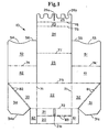
- Blank 10 can be formed of a single piece of corrugated cardboard, fiberboard, or the like, and is of conventional thickness.
- Blank 10 comprises a front panel including an outer front panel 20 and an inner front panel 21, a bottom panel 22, a rear panel 23 and a top panel 24 foldably connected together in serial relation along parallel transverse score lines 72, 73 and 77, respectively.
- the front panel is divided into its inner and outer portions by double score line 83.
- the parallel individual score lines making up double score line 83 are preferably spaced from one another at a distance of approximately twice the thickness of the container blank material to allow a comfortable fit of intermediate front flaps 61 and 62 between outer and inner front panels 20 and 21, as will be described"below.
- Top panel extension 25 is hingedly connected along score line 75 to the distal edge of top panel 24, and re-entrant retainer flap 26 is hingedly connected along score line 76 to the top distal edge of extension 25.
- Re-entrant flap 26 is shown including a centrally located longitudinal retainer slot 26a and a plurality of cutouts 26b spaced along its distal edge.
- hingegedly connected along parallel score lines 71 to the opposite lateral edges of bottom flap 22 are the right and left outer side panels, 32 and 33, respectively.
- a pair of right and left inner side panels, 31 and 34 are integrally connected to the distal edge of corresponding outer side panels 32 and 33 along double score lines 81 and 82, respectively.
- inner side panels 31 and 34 will be folded inwardly during the container erection procedure such that their bottom edges, 31a and 34a, create an interference or frictional fit with bottom panel 22, thereby retaining the inner side panels 31 and 34 in face to face relationship with corresponding outer panels 32 and 33.
- the parallel individual score lines of double score lines 81 and 82 should be spaced at a distance of approximately twice the thickness of the carton blank material, thereby providing a smooth surface (35 and 36) on the upper edges of the containers side walls. While it is not critical to have such smooth upper surfaces of the side walls of the container, as will be discussed with relation to Figures 5 and 6, such smooth surfaces are preferred for overall container appearance and consumer appeal.
- Hingedly connected along transverse score line 72 to the front edge of corresponding outer side panels 32 and 33 is a pair of right and left intermediate front flaps 61 and 62, respectively.
- each inner rear panel 41 and 42 also has a divider flap (51 and 52) integrally connected to its distal rear edge along score line 74.
- divider flaps 51 and 52 have a portion of their distal edges removed (as shown at 53 and 54) to facilitate product display and access within the completed container.
- the lowermost edges (55 and 56, respectively) be formed as tab sections which, as will be shown, can be integrally locked into a slot (as shown at 21a) or slots (not shown) formed in from anel 21 for added container rigidity.
- Slot 21a extends longitudinally across substantially the entire height of inner front panel 21 and has a width of approximately two times the thic less of the carton blank material.
- dividers 51 and 52 will be in face to the relationship, as shown in Figure 3, in order to serve the Dual function as a central partition wall and as a vertical support member for top panel 24.
- Divider panels 51 and 52 could be spaced apart to provide dual dividing walls and dual vertica support, however, such an arrangement might sacrifice effective display area and limit accessability to the contents of the container.
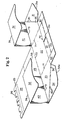
- divider flaps 51 and 52 are folded upwardly 90° along, score line 74 and then inner rear flaps 41 and 42 are likewise folded upwardly 90° along score line 73, as shown in Figure 2.
- the side walls (31 and 32, and 33 and 34, respectively) are then folded inwardly 90° about the parallel score lines 71, thereby bringing divider flaps 51 and 52 into face to face contact, as seen in Figure 3.
- inner side walls 31 and 34 can be folded inwardly 180° such that their lower edges (31a and 34a, respectively) act to frictionally hold the respective inner side panels against bottom panel 22 and in face to face relation with outer side panels 32 and 33, respectively.
- double score lines 81 and 82 provide a smooth upper surface (35 and 36, respectively) for the double side wall panels.
- smooth side wall surfaces are not critical to the successful practice of the invention. Smooth surfaces are preferred, however, to provide an overall more finished appearance and quality to the container.
- outer rear panel 23 adhesive can be applied to the inner surface of outer rear panel 23, and thereafter outer rear panel 23 is folded inwardly and upwardly 90° about score line 73 and adhered to the outer surfaces of the inner rear panels 41 and 42.
- the partially completed container can be front (gang) loaded or top loaded with packaged product.
- the container is further erected as the front panel, comprising inner front panel 21 and outer front panel 20, is folded inwardly and upwardly 90° about score line 72 such that the locking tabs 55 and 56 of divider panels 51 and 52 extend into slot 21a for locking engagement therewith.
- the locking relationship of divider panels 51 and 52 with front panel 21 is not absolutely necessary, however, it is preferred in order to provide lateral support to the divider panels and to increase the overall rigidity of the container.
- Adhesive can now be applied to the inner surfaces of the intermediate front panels 61 and 62, and these panels are then folded inwardly 90° about score line 72 and adhered to the outer surfaces of inner front flap 21.
- the partially completed container is shown in Figure 3. it is contemplated that the precise details of the application of adhesive to the various container elements may be varied to best suit the assembly equipment being utilized.
- Adhesive can now be applied to either the outer surface of outer front panel 20 and/or the outer surfaces of the intermediate front flaps 61 and 62. Thereafter, outer front flap 20 is folded outwardly and downwardly 180° about double-score line 83 and adhered to the outer surfaces of the intermediate front flaps 61 and 62. If product has not been previously loaded, product can be top loaded into the partially completed container 12 at this time. It should be noted that although outer front flap 20 is preferably included to provide a more substantial front container panel and a more finished appearance, it is within the scope of this invention to omit front flap 20 completely.
- top closure is completed by folding top panel 24 inwardly 90° about score line 77, folding top panel extension 25 inwardly 90° about score line 75, and folding re-entrant retainer flap 26 inwardly approximately 90° about score line 76 such that retainer slot 26a lockingiy engages divider flaps 51 and 52 within the container, and cutouts 26b supportingly nest around the upper portions of at least some of the packaged products contained within container 12.
- Score lines 75, 76 and 77 are shown as perforated score lines to insure accurate folding during erection procedures. Perforating score lines is commonly used where such accurate folding is required, however, the details of how the score lines are formed are not critical to the instant invention.
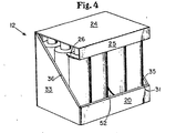
- the completed container 12 is Illustrated in Figure 4.
- Retainer slot 26a serves to lock top panel 24 into its closed position, while cutouts 26b augment the locking action and add greater stability to the product contained therewithin.
- cutouts 26b are not critical to the successful practice of the current invention. it is only important that the retainer flap serve to lock top panel 24 in its closed position. While it is preferred that re-entrant flap 26 include cutouts in its distal edge having a shape substantially complementary to the upper portions of at least a portion of the packaged products contained, it is contemplated that the distal edge could function adequately without cutouts whereby re-entrant flap 26 would lockingly engage the divider flaps and -simply butt up against the contained packaged products.
- cutouts 26b could serve to lock top panel 24 in its closed position, exclusive of the slot 26a, by locking around the upper portions of the contained products. In such case, slot 26a could be omitted or enlarged sufficiently to no longer serve a locking function.
- top panel 24 serves to contain the packaged products and, together with the divider panels 51 and 52, provides substantial stacking strength to the container for shipping and display purposes.
- the completed container of the present invention (e.g. as illustrated in Figure 4) provides support for contained products in substantially all directions of external loading, and can be handled in a manner similar to a "buiiding block" to prepare displays and/or shipping loads due to its substantially uniform rectangular surfaces and its strong squared configuration. Such attributes make the subject container invaluably versatile in the industry.
- the completed container- may also be overwrapped with shrink film, stretch wrap or other similar coverings for added strength and cleanliness during shipping and handling. Individual containers can thereafter be shipped individually or stacked and shipped on pallets, such as pre-built displays. Further, an entire stack of containers, or a pre-built display, can be conveniently unitarily wrapped so that only removal of such wrap need be undertaken at the retail store.
- Alternative display procedures can include unlocking re-entrant flap 26 from its interlocked arrangement, folding top panel 24 back 270° and tucking top panel extension 25 and re-entrant flap 26 underneath the container 12, thereby providing a substantially open tray-type display.
- a similar open tray-type display can be accomplished by heavily perforating score line 77 of blank 10 so that the top portion of the container can be easily removed for display purposes.
- Top panel 24 can also be folded back 180° for interlocking support on multi-tiered display units. It tan thus be seen that there are many ways to utilize the container of the present invention for convenient display with minimum handling requirements. The uses discussed herein are meant to serve only as examples and not in any way to limit the teachings of the present invention.
- the relative dimensions of the front and side panels are to be such as to provide sub tantiaUy open front and side walls for display purposes. In this regard, some situations may require larger front and side panels to ensure adequate support for shipping and handling; however, to take full advantage of the present invention the front and side walls should remain substantially open.
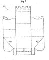
- Figure 5 illustrates a container blank of an alternate embodiment of the present invention wherein single perforated score lines 181 and 182 replace the double score lines 81 and 82, respectively, as shown and described above with respect to Figures 1 through 4.
- the procedure for erecting the blank 100 of Figure 5 is essentially exactly the same as that described above with regard to blank 10.
- the container formed from blank 100 would look substantially identical to the container 12 of Figure 4, with the exception that the flat surfaces 35 and 36 would appear as a single perforated fold line 181 between the inner and outer side panels.
- Figure 6 illustrates the carton blank of another alternate embodiment of the present invention featuring single side wall panels 232 and 233, respectively.
- blank 200 is erected in a substantially identical manner to the procedures described above regarding blank 10, however, the inner side wall folding step will be omitted for obvious reasons.
- the upper edges, 281 and 282, of side wall panels 232 and 233, respectively, are shown in Figure 6 as including a plurality of serrations. Such serrations are shown only as an example of the unlimited ways in which the side wall edges can be formed in any desirable configuration.
- edges 281 and 282 could be formed as a smooth cut (e.g., see edges 381 and 382 of Figure 7) and/or could be formed with a non-linear shape (not shown) to provide additional open display area and access to the contents of the container.
- containers erected from any of the blanks shown herein can also be overwrapped for shipping purposes, and can be shipped as an individual unit or conveniently stacked for multi-unit shipment.
- the corresponding distal (front) edges of the divider panels in the other blanks shown blanks i.e.. 153 and 154, 253 and 254, and 353 and 354, respectively
- Figures 7 through 9 illustrate another example of a container made in accordance with the present invention having an additional feature of being dividable into subcontainers in use.
- Figure 7 shows the inner surface.of container blank 300, which is quite similar in appearance to blank 200 of Figure 6.
- divider flap securing tabs 355 and 356 are formed on the lower distal edge of divider flaps 351 and 352, respectively.
- side wall edges 381 and 382 have been cut smooth for illustration purposes. Securing tabs 355 and 356 will extend into the centrally located slot 321a as inner front flap 321 is folded upwardly during the erection procedure.
- the erection procedure is substantially identical to that described above with respect to blank 200, except that after securing tabs 355 and 356 are extended through slot 321a, they are folded 90° outwardly and their inner surfaces are adhesively joined to the outer surface of inner front flap 321.
- Figure 8 shows the partially assembled view of container 312 with securing tabs 355 and 356 adhesively secured to inner front flap 321, as described.
- intermediate front flaps 361 and 362 can be formed with their distal edges having a shape complementary to that of the distal edges of securing tabs 355 and 356, although this is not essential. Such complementary shape might be preferred, however, especially if outer front flap 320 were to be omitted.
- Blank 300 is also provided with a line of severance 390 extending longitudinally across outer front panel 320, bottom panel 322, outer rear panel 323, top panel 324, top panel extension 325. and retainer panel 326 in alignment with the centrally located slots 321a and 326a.
- tine of severance 390 can be perforations, lines of weakness, slits, a removable tear tape, a combination of these elements, or merely printed indicia to facilitate cutting; and is designed to facilitate separation of portions of the container lying on opposite sides of the line into subcontainers.
- a blank (not shown) could be provided with line of severance 390 having slits formed across a substantial portion of bottom panel 322 and outer rear panel 323, perforations formed across outer front panel 20, and printed indicia across top panel 324, extension panel 325 and retainer panel 326.
- the resulting container could be easily divided by simply cutting along the top, top extension, and retainer panels, and then popping the container apart along the perforations.
- a tear tab 391 is shown in Figure 7 as a means to further facilitate the separation of the two subcontainers.
- Tear tab 391 could be a perforated finger tab, or an open finger hole, or the like, and might be desirable to provide a convenient location to begin removal of a tear tape, to facilitate a cutting procedure, or to facilitate separation along lines of weakness. It is preferred that slots 321a and 326a be centrally located in order to provide two substantially equally sized subcontainers, but this is not essential.
- FIG. 9 shows container 312 after it has been divided into two subcontainers (312a and 312b, respectively) along the line of severance 390.
- each subcontainer is a complete container in itself which can be further shipped and/or displayed (without a need for additional packing material or container modification) as described above with regard to the other embodiments shown and discussed.
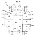
- Figure 10 Illustrates the carton blank of yet another alternate embodiment of the present invention featuring modified front panel and side panel structures, and including a particularly preferred method of interlocking the divider panels and the top flap extension.
- Figure 10 discloses carton blank 400 which is to be crected in a substantially similar manner to the procedures destribed above regarding blank 200. Erection of the front panels of carton blank 400 differs slightly in that inner front flaps 461 and 462 are to be folded inwardly about score lines 482 and 483, respectively, and adhered to the inner surface of front flap 421 when sidewalls 432 and 433 and front flap 421 are folded upwardly.
- divider flap securing tabs 455 and 456, respectively are to be folded inwardly so that they extend outwardly in the assembled position and can be adhered to the inner surface of front flap 421.
- the combined length of inner front flaps 461 and 462 and divider flap securing tabs 455 and 456 is preferably equal to or less than the width of front flap 421.
- inner front flap 461 is illustrated as being slightly longer than inner front flap 462, while divider flap securing tab 455 is inversely shorter than securing tab 456 in order to facilitate the necessary folding and erection procedures on automatic manufacturing equipment.
- Such designed dimensional inconsistencies are commonly employed in the industry for this purpose and are not considered critical to the unique structure and utility of the subject container.
- inner top panel front f ps 426 and 427 are folded upwardly about score lines 478 and 9, respectively. and then inwardly (as sidewall extensions 428 t d 429 are folded upwardly) such that their outer surface can be a Jhered to the inner surface of the upwardly folded top panel front flap 425.
- Top panel 424 can then be folded forwardly abou score line 477 to effectively close the top of the erected contair ; 412, and can be effectively "locked” in place by the locking enement of locking edges 451a and 452a of the divider flaps with top panel front flap slot 425a (as shown in Figure 11).
- locking edges 451a and 452a include an appropriate locking lip or horizontal edge L to positively interlock with slot 425a. It should be understood that in applications where divider flaps 451 and 452 are- spaced apart to provide dual dividing walls, a pair of top panel front flap slots 425a would be required. As mentioned above, the precise manner of accomplishing the locking engagement of top panel front flap 425 with divider flaps 451 and 452 is not critical and can be accomplished in a variety of ways. Positive locking is preferred, however, for more reliable protection during shipping and handling.
- sidewalls 432 and 433 include a portion (432a and 433a, respectively) near their proximal rear edge having a height substantially equal to the height of rear wall 423. While not critical to the container structure, side wall top flap supports 432a and 433a add significant columnar support to top flap 424 and augment the overall rigidity to container 412. Similarly, it is preferred that top flap sidewall extensions 428 and 429 be included in container blank 400 to add strength and rigidity to top panel 424 and top panel front flap 425. Sidewall extensions 428 and 429 are shown as being hingedly attached along the distal lateral edges of top flap 424.
- sidewall extensions can be rigidly fixed in a manner shown in Figures 11 and 12 as being hingedly connected to both top panel 424 and one of inner top panel front flaps 426 or 427, respectively, which are in turn adhered to the inner surfaces of top panel front flap 425 as described above.
- Sidewall extensions 428 and 429 additionally add lateral constraint to product packaged within container 412.
- Blank 400 may also be provided with a line of severance 495 extending longitudinally across the top panel front flap 425, top flap 424, rear flap 423, bottom panel 422, and front flap 421. It is preferred that such line of severance be in alignment with the centrally located locking slot 425a. As described relative to container blank 300 above, such line of severance 495 can be perforations, lines of weakness, slits, a removable tear tape, a combination of these elements, or merely printed indicia to facilitate cutting; and is similarly designed to facilitate separation of portions of container 412 lying on opposite sides of line 495 into subcontainers.
- line of severance 495 be spaced slits or perforations to provide for convenient division of container 412.
- Blank 400 and the erected container 412 are shown as including line of severance 495, which comprises a combination of perforations and slits as an example of a preferred manner of providing convenient division of container 412.
- Figure 12 shows container 412 after it has been divided into two subcontainers (412a and 412b, respectively) along the line of severance 495.
- each subcontainer 412a and 412b is a complete container in itself which can be further shipped and/or displayed as described above.
- fold-out locking tabs 491 and 492 be formed in divider flaps 451 and 452, respectively, in order to provide alternate means of locking top panel 424 in closed condition.
- a preferred means of providing such alternate locking means for top panel 424 includes fold-out locking tabs 491 and 492 which are folded outwardly and upwardly around the edge of top panel 424 and tucked into tab locking slit 424a and 424b, respectively, formed in top panel 424.
- Tab locking slit 424a is illustrated as including a single slit having two or more short, radially divergent slits (or crow-footed siits) at either end.
- Locking tabs 491 and 492 are illustrated as including a base portion and an enlarged locking end. It is preferred that tab locking slit 424a have a length substantially equal to the width of the base of the locking tabs, and the crow-footed ends of tab locking slits 424a and 424b thereby allow the insertion of the enlarged end of the locking tabs therethrough.
- the distal end of the enlarged locking end of the tabs is tapered to facilitate insertion through the tab locking slits, and includes substantially horizontal undercut portions to effectively lock the tabs within the tab locking slits once inserted therethrough.
- container 412 In use, after container 412 is divided into two subcontainers, and locking tabs 491 and 492 are folded outwardly and over top panel 424 for locking insertion with tab locking slits 424a and 424b, respectively, the subcontainers 412a and 412b are ready for further shipping, handling and display.
- the convenient re-locking features of both the complete container 412 and the individual subcontainers 412a and 412b permit opening of the containers for price marking, product exchange, and the like during shipping; and subsequent convenient reclosure for further shipping and handling in either full or partial case lots.
- container 412 combines these advantages with efficient blank material usage and the ability to be manufactured on automatic machinery commonly available in the industry.
Landscapes
- Engineering & Computer Science (AREA)
- Mechanical Engineering (AREA)
- Cartons (AREA)
Applications Claiming Priority (2)
| Application Number | Priority Date | Filing Date | Title |
|---|---|---|---|
| US63031284A | 1984-07-12 | 1984-07-12 | |
| US630312 | 1984-07-12 |
Publications (2)
| Publication Number | Publication Date |
|---|---|
| EP0168098A2 true EP0168098A2 (fr) | 1986-01-15 |
| EP0168098A3 EP0168098A3 (fr) | 1987-04-01 |
Family
ID=24526676
Family Applications (1)
| Application Number | Title | Priority Date | Filing Date |
|---|---|---|---|
| EP85201020A Withdrawn EP0168098A3 (fr) | 1984-07-12 | 1985-06-27 | Récipient pour le transport et l'étalage, en forme de plateau |
Country Status (3)
| Country | Link |
|---|---|
| EP (1) | EP0168098A3 (fr) |
| JP (1) | JPS6193046A (fr) |
| ES (2) | ES288016Y (fr) |
Cited By (4)
| Publication number | Priority date | Publication date | Assignee | Title |
|---|---|---|---|---|
| GB2262086A (en) * | 1991-11-13 | 1993-06-09 | Mclaren Packaging Ltd | Packaging e.g. for bottles or cans |
| WO2001028877A1 (fr) * | 1999-10-18 | 2001-04-26 | Qpod Systems Limited | Systeme d'acces a un panneau de pliage |
| DE102009007147B4 (de) * | 2009-02-02 | 2012-08-16 | Thimm Verpackung Gmbh + Co. Kg | Einteiliger Zuschnitt für eine Displayverpackung und mit dem Zuschnitt hergestellte Displayverpackung |
| DE102012025017A1 (de) * | 2012-12-20 | 2014-06-26 | Smurfit Kappa Gmbh | Warenständer |
Families Citing this family (1)
| Publication number | Priority date | Publication date | Assignee | Title |
|---|---|---|---|---|
| JP2820127B2 (ja) * | 1996-07-29 | 1998-11-05 | 株式会社日立製作所 | 半導体のリード曲げ加工法 |
Family Cites Families (4)
| Publication number | Priority date | Publication date | Assignee | Title |
|---|---|---|---|---|
| US2896780A (en) * | 1956-01-13 | 1959-07-28 | Diamond Gardner Corp | Cartons |
| US3080966A (en) * | 1960-10-13 | 1963-03-12 | American Can Co | Can package |
| US3099380A (en) * | 1961-11-13 | 1963-07-30 | Irwin E Nathan | Separable compartmented container |
| US4213559A (en) * | 1978-04-05 | 1980-07-22 | American Can Company | Divided display carton |
-
1985
- 1985-06-27 EP EP85201020A patent/EP0168098A3/fr not_active Withdrawn
- 1985-07-11 ES ES1985288016U patent/ES288016Y/es not_active Expired
- 1985-07-12 JP JP60152621A patent/JPS6193046A/ja active Pending
-
1986
- 1986-03-17 ES ES1986293003U patent/ES293003Y/es not_active Expired
Cited By (5)
| Publication number | Priority date | Publication date | Assignee | Title |
|---|---|---|---|---|
| GB2262086A (en) * | 1991-11-13 | 1993-06-09 | Mclaren Packaging Ltd | Packaging e.g. for bottles or cans |
| WO2001028877A1 (fr) * | 1999-10-18 | 2001-04-26 | Qpod Systems Limited | Systeme d'acces a un panneau de pliage |
| DE102009007147B4 (de) * | 2009-02-02 | 2012-08-16 | Thimm Verpackung Gmbh + Co. Kg | Einteiliger Zuschnitt für eine Displayverpackung und mit dem Zuschnitt hergestellte Displayverpackung |
| DE102012025017A1 (de) * | 2012-12-20 | 2014-06-26 | Smurfit Kappa Gmbh | Warenständer |
| DE102012025017B4 (de) * | 2012-12-20 | 2015-10-01 | Smurfit Kappa Gmbh | Warenständer |
Also Published As
| Publication number | Publication date |
|---|---|
| EP0168098A3 (fr) | 1987-04-01 |
| ES288016U (es) | 1986-07-01 |
| ES293003Y (es) | 1987-04-16 |
| ES293003U (es) | 1986-08-01 |
| ES288016Y (es) | 1987-03-16 |
| JPS6193046A (ja) | 1986-05-12 |
Similar Documents
| Publication | Publication Date | Title |
|---|---|---|
| US4641746A (en) | Tray-type shipping and display container | |
| US7413101B2 (en) | Dispensing package | |
| EP0016877B1 (fr) | Porte-objets | |
| EP1682418B1 (fr) | Emballage de distribution | |
| US5145070A (en) | One-piece corrugated box with interior supports | |
| US6244502B1 (en) | Self-dividing box, components thereof, and method of manufacturing, assembly and disassembling the same | |
| US4946042A (en) | Readily openable combination shipping and display carton | |
| US4605128A (en) | Dispensing carrier box and blank | |
| US6988617B2 (en) | Bottom locking carton | |
| US6227370B1 (en) | Tiered pack | |
| US5263612A (en) | Fibreboard container for fresh produce | |
| US5520325A (en) | Channel H divider pack | |
| US4267959A (en) | Hinged paperboard container | |
| US4300679A (en) | Self locking folder | |
| US5758818A (en) | Dividable multi-compartment container | |
| US6105774A (en) | Carton for packaging containers | |
| US5645163A (en) | Detachable multi-unit package having internal handle | |
| JPH11500696A (ja) | 物品ディスペンサー付きキャリヤー | |
| US5447225A (en) | Preassembled tray/shroud container | |
| US3372800A (en) | Article carrier | |
| AU8109987A (en) | Carton and blank therefor | |
| US5447269A (en) | Multiple unit box and blank therefor | |
| EP2765085A1 (fr) | Conteneur d'expédition et présentoir pliable en plateaux de présentation avec des caractéristiques antibasculement et découpe associée | |
| US4989779A (en) | Bottom lock arrangement for cartons | |
| EP1784338A1 (fr) | Carton à bouteilles |
Legal Events
| Date | Code | Title | Description |
|---|---|---|---|
| PUAI | Public reference made under article 153(3) epc to a published international application that has entered the european phase |
Free format text: ORIGINAL CODE: 0009012 |
|
| AK | Designated contracting states |
Designated state(s): AT BE CH DE FR GB IT LI NL |
|
| PUAL | Search report despatched |
Free format text: ORIGINAL CODE: 0009013 |
|
| AK | Designated contracting states |
Kind code of ref document: A3 Designated state(s): AT BE CH DE FR GB IT LI NL |
|
| 17P | Request for examination filed |
Effective date: 19870827 |
|
| 17Q | First examination report despatched |
Effective date: 19871105 |
|
| STAA | Information on the status of an ep patent application or granted ep patent |
Free format text: STATUS: THE APPLICATION HAS BEEN WITHDRAWN |
|
| 18W | Application withdrawn |
Withdrawal date: 19881024 |
|
| RIN1 | Information on inventor provided before grant (corrected) |
Inventor name: SCHANZLE, ROGER EVAN Inventor name: DORNBUSCH, ARTHUR HAROLD |