EP0168237A2 - Piston and cylinder apparatus - Google Patents
Piston and cylinder apparatus Download PDFInfo
- Publication number
- EP0168237A2 EP0168237A2 EP85304859A EP85304859A EP0168237A2 EP 0168237 A2 EP0168237 A2 EP 0168237A2 EP 85304859 A EP85304859 A EP 85304859A EP 85304859 A EP85304859 A EP 85304859A EP 0168237 A2 EP0168237 A2 EP 0168237A2
- Authority
- EP
- European Patent Office
- Prior art keywords
- piston
- sleeve
- bearing
- cylinder
- piston core
- Prior art date
- Legal status (The legal status is an assumption and is not a legal conclusion. Google has not performed a legal analysis and makes no representation as to the accuracy of the status listed.)
- Granted
Links
- 239000000463 material Substances 0.000 claims abstract description 9
- -1 polytetrafluorethylene Polymers 0.000 claims description 6
- 229920001343 polytetrafluoroethylene Polymers 0.000 claims description 6
- 230000037431 insertion Effects 0.000 claims description 4
- 238000003780 insertion Methods 0.000 claims description 4
- OKTJSMMVPCPJKN-UHFFFAOYSA-N Carbon Chemical compound [C] OKTJSMMVPCPJKN-UHFFFAOYSA-N 0.000 claims description 3
- 239000004696 Poly ether ether ketone Substances 0.000 claims description 3
- 229910052799 carbon Inorganic materials 0.000 claims description 3
- 239000004033 plastic Substances 0.000 claims description 3
- 229920003023 plastic Polymers 0.000 claims description 3
- 229920002530 polyetherether ketone Polymers 0.000 claims description 3
- 230000006835 compression Effects 0.000 claims description 2
- 238000007906 compression Methods 0.000 claims description 2
- 241001125877 Gobio gobio Species 0.000 claims 1
- 238000007789 sealing Methods 0.000 abstract description 5
- 241001125879 Gobio Species 0.000 description 13
- 239000011324 bead Substances 0.000 description 10
- 239000004411 aluminium Substances 0.000 description 5
- XAGFODPZIPBFFR-UHFFFAOYSA-N aluminium Chemical compound [Al] XAGFODPZIPBFFR-UHFFFAOYSA-N 0.000 description 5
- 229910052782 aluminium Inorganic materials 0.000 description 5
- 238000000748 compression moulding Methods 0.000 description 2
- 239000010687 lubricating oil Substances 0.000 description 2
- 238000005461 lubrication Methods 0.000 description 2
- 239000003921 oil Substances 0.000 description 2
- 230000000717 retained effect Effects 0.000 description 2
- 229910001018 Cast iron Inorganic materials 0.000 description 1
- 238000010276 construction Methods 0.000 description 1
- 230000000694 effects Effects 0.000 description 1
- 239000007924 injection Substances 0.000 description 1
- 238000001746 injection moulding Methods 0.000 description 1
- 238000003754 machining Methods 0.000 description 1
Images

Classifications
-
- F—MECHANICAL ENGINEERING; LIGHTING; HEATING; WEAPONS; BLASTING
- F16—ENGINEERING ELEMENTS AND UNITS; GENERAL MEASURES FOR PRODUCING AND MAINTAINING EFFECTIVE FUNCTIONING OF MACHINES OR INSTALLATIONS; THERMAL INSULATION IN GENERAL
- F16J—PISTONS; CYLINDERS; SEALINGS
- F16J15/00—Sealings
- F16J15/16—Sealings between relatively-moving surfaces
- F16J15/32—Sealings between relatively-moving surfaces with elastic sealings, e.g. O-rings
- F16J15/3204—Sealings between relatively-moving surfaces with elastic sealings, e.g. O-rings with at least one lip
-
- F—MECHANICAL ENGINEERING; LIGHTING; HEATING; WEAPONS; BLASTING
- F16—ENGINEERING ELEMENTS AND UNITS; GENERAL MEASURES FOR PRODUCING AND MAINTAINING EFFECTIVE FUNCTIONING OF MACHINES OR INSTALLATIONS; THERMAL INSULATION IN GENERAL
- F16J—PISTONS; CYLINDERS; SEALINGS
- F16J1/00—Pistons; Trunk pistons; Plungers
- F16J1/02—Bearing surfaces
-
- F—MECHANICAL ENGINEERING; LIGHTING; HEATING; WEAPONS; BLASTING
- F05—INDEXING SCHEMES RELATING TO ENGINES OR PUMPS IN VARIOUS SUBCLASSES OF CLASSES F01-F04
- F05C—INDEXING SCHEME RELATING TO MATERIALS, MATERIAL PROPERTIES OR MATERIAL CHARACTERISTICS FOR MACHINES, ENGINES OR PUMPS OTHER THAN NON-POSITIVE-DISPLACEMENT MACHINES OR ENGINES
- F05C2225/00—Synthetic polymers, e.g. plastics; Rubber
- F05C2225/04—PTFE [PolyTetraFluorEthylene]
Definitions
- This invention relates to piston and cylinder apparatus and relates especially but not exclusively to such apparatus wherein a piston is intended to operate in a cylinder without added lubrication.
- a piston and cylinder apparatus having a substantially non-deformable piston core characterised by a bearing or wear sleeve located thereon before insertion into the cylinder bore, said sleeve being formed of a materiial offering sliding wear resistance compatible with the cylinder bore and being provided with an integral inwardly resiliently deflectable compression seal slidingly and sealingly engageable with the cylinder bore.
- said bearing or wear sleeve extends over the full length of the skirt of the piston and is provided with an inner bead locatable with the piston core.
- the moulded sleeve may be closed at one end so as to enclose the head of the piston core.
- said bearing or wear sleeve may be located in a circumferential groove of the piston.
- a further bearing or wear ring may be located in a groove near the lower end of a . skirt D f the piston.
- a cylinder head and valve-plate assembly which is normally bolted on is represented by the block 2.
- the gudgeon pin end of a connecting rod 3 is provided with a sealed-in needle bearing 4 and a gudgeon pin 5 with end pads, one of which is shown at 6.
- the gudgeon pin 5 is retained in an aluminium piston core 7 by means of locked-in set screws 16.
- the piston core 7 is provided with a moulded polytetrafluorethylene cup-shaped bearing shroud 8 before insertion into aluminium bore of cylinder 1.
- the natural moulded form of the skirt of shroud 8 is as shown at 9 in Fig. 1(b) of the drawings.
- the lower edge of the skirt carries an inwardly projecting bead 12 of thickness which varies as shown in Fig. 1(c) and which when deflected inwards engages a rebate at the lower edge 13 of the skirt of the inner core 7.
- the skirt of the cup-shaped liner has axial slots such as 15 extending upwards to a point somewhat below the root of the sealing part 10.
- Surrounding a head-portion 14 which is of smaller diameter than the remainder of the piston skirt, there is resiliently deformable annular sealing part 10, the undeformed shape of which is shown in Fig. 1(b).
- lugs may be provided within the shroud 8 to locate in the transverse gudgeon pin recesses of the piston core 7 to retain the sleeve in position on the core.
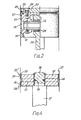
- FIG. 2 an alternative piston construction is shown wherein the gudgeon pin end of a connecting rod 23 is provided with a sealed bearing or bush 24 and the gudgeon pin is again located in the core of the piston by a small locked locating set-screw 25.
- the piston core is formed of a lower part 21 between which and an upper part 22 is clamped, by screws 20, an an inwardly projecting annular retaining bead 26 of a carbon-filled polytetrafluorethylene bearing sleeve.
- the bearing sleeve has a resiliently deformable seal bead 28 similar to the seal bead 11 of Fig. 1 and a similarly slotted skirt portion 29 with a lower inwardly projecting bead 30 locating in an annular rebate 31 formed in the lower edge of the piston core part 21.
- the lower bead 30 may be dispensed together with and the mentioned slots.
- the skirt is then required simply to be press-fitted over the lower part 21 of the piston core before attachment of the upper part 22.
- the gudgeon pin 25 may be located by screws such as 20 which are positioned and having projections made long enough to extend into one or more suitable locating holes provided in the gudgeon pin.
- the mentioned holes in the gudgeon pin may be tapped with screw threads to receive the screws 20 which are then preferably a clearing fit in the lower part of the piston core.
- the lower part of the piston core may be cut away in way of the gudgeon pin permitting assembly of the gudgeon pin thereto from beneath to be retained in position by screws tapped into the gudgeon pin.
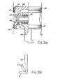
- the bearing shroud (8) may be replaced, as shown in Fig. 3 by upper and lower bearing rings 40 and 41 located in respective grooves 42 and 43 formed in the main body 44 of an aluminium air compressor piston.
- the gudgeon pin 45 is located in the transverse bore 46 of the piston by at least one retaining screw 47.
- the connecting rod 48 is pivotable on a sealed bush or bearing 49 as before.
- the upper bearing-ring 40 is fomred with a section generally as shown on an enlarged scale in Fig. 4b from which it will be seen that this ring comprises an upper thickened bearing-portion 50 and a lower portion 51 which extends radially upwards and is deflectable through a position such as shown dotted when the piston is inserted in an aluminium bore of a cylinder indicated by the broke lines 52 of Fig. 3(a).
- the upper bearing-ring 40 and the lower bearing-ring 41 are manufactured by compression moulding or by machining from a suitably carbon-filled polytetrafluorethylene material but other suitable plastics materials such as polyetheretherketone may be used.
- the dimensions of these bearing-rings and the depth of the upper and lower grooves 42 and 43 formed in the piston body 44 are such as to permit the bearing-rings 40 and 41 to be stretched over the external diameter of the main body 44 to locate in the respective sections.
- the essential requirement for the war-rings is that they both shall jointly operate to prevent contact between the piston44 and the interior of the cylinder bore 52 and a sufficiently good degree of sealing is provided by the seal-portion 51 through the useful life of the compressor.
- a non-deformable piston core 32 is carried on a spigot 38 of a piston rod 39.
- a resiliently deformable polytetrafluorethylene wear sleeve 33 is stretched over the periphery of the piston, an inner bead 34 of the sleeve serving to position and retain the sleeve on the piston core by engaging with a matching groove 35 of the core.
- the sleeve is further provided with two annular deformable seal parts 35, 36 the undeformed shape of which is again shown at 35 and 36.
- seal parts are resiliently deformed on assembly to make sealing and sliding contact with the bore 37 of a cylinder as shwon and they are arranged to act in opposing senses in relation to the cylinder bore so that a double acting piston is provided with a single deformable bearing sleeve.
- piston core of each of the above described embodiments is preferably to be made of aluminium, other suitable substantially non-deformable materials may be used.
- suitable plastics material being used the advantages of injection or compression moulding may be enjoyed.
- bearing or wear rings or sleeves are made of polytetrafluorethylene, other materials such as polyetheretherketone may be employed.
Landscapes
- Engineering & Computer Science (AREA)
- General Engineering & Computer Science (AREA)
- Mechanical Engineering (AREA)
- Chemical & Material Sciences (AREA)
- Combustion & Propulsion (AREA)
- Compressor (AREA)
Abstract
Description
- This invention relates to piston and cylinder apparatus and relates especially but not exclusively to such apparatus wherein a piston is intended to operate in a cylinder without added lubrication.
- The most commonly used air compressors for charging reservoirs in compressed air systems such as installed on vehicles for braking and other functions employ conventional metallic piston reciprocably slideable in cast iron cylinder bores and they require a suitable lubricating oil supply. Such compressors are usually driven by the vehicle engine and also receive their lubricating oil supply from the engine. There is, therefore, an inherent practical constraint placed upon the positioning of the compressor on the vehicle.
- Additionally, such compressors tend to permit carry-over of oil vapour or droplets with the compressed air into the compressed air system and precautions such as filters and drain valves are essential to prevent such oil reaching sensitive working parts of the system. Such filters tend to become blocked and therefore require frequent replacement.
- Various proposals have been made to construct substantially "oil-free" piston and cylinder compressors the bearings of which have sealed-in lubrication and one object of the invention is to provide an improvement to such compressors.
- According to the present invention there is provided a piston and cylinder apparatus having a substantially non-deformable piston core characterised by a bearing or wear sleeve located thereon before insertion into the cylinder bore, said sleeve being formed of a materiial offering sliding wear resistance compatible with the cylinder bore and being provided with an integral inwardly resiliently deflectable compression seal slidingly and sealingly engageable with the cylinder bore.
- In one embodiment said bearing or wear sleeve extends over the full length of the skirt of the piston and is provided with an inner bead locatable with the piston core.
- The moulded sleeve may be closed at one end so as to enclose the head of the piston core.
- In an alternative embodiment, said bearing or wear sleeve may be located in a circumferential groove of the piston.
- In an embodiment when the groove of the piston is located near the top of the piston a further bearing or wear ring may be located in a groove near the lower end of a . skirt Df the piston.
- In order that the invention may be more clearly understood and readily carried into effect the same will be further described by way of example with reference to tne accompanying drawings of wnicn:
- Fig. 1(a) illustrates one example in part-sectional diagrammatic view,
- Fig. 1(b) illustrates in its free state a moulded piston sleeve used in the apparatus of Fig.1.
- Fig. 1(c) is a further view of the moulded sleeve taken on the direction of the arrow 'A'.
- Figs. 2 and 3 illustrate an alternative embodiments and
- Fig. 4 illustrates an example of a double acting piston assembly.
- Referring to the part-sectional view of a portion of a single cylinder air compressor, as shown in Fig. 1 of the drawing, the cylinder is denoted by
reference 1 and a cylinder head and valve-plate assembly which is normally bolted on is represented by the block 2. The gudgeon pin end of a connectingrod 3 is provided with a sealed-in needle bearing 4 and a gudgeon pin 5 with end pads, one of which is shown at 6. The gudgeon pin 5 is retained in an aluminium piston core 7 by means of locked-in setscrews 16. The piston core 7 is provided with a moulded polytetrafluorethylene cup-shaped bearingshroud 8 before insertion into aluminium bore ofcylinder 1. The natural moulded form of the skirt ofshroud 8 is as shown at 9 in Fig. 1(b) of the drawings. The lower edge of the skirt carries an inwardly projectingbead 12 of thickness which varies as shown in Fig. 1(c) and which when deflected inwards engages a rebate at thelower edge 13 of the skirt of the inner core 7. To permit such inward deflection the skirt of the cup-shaped liner has axial slots such as 15 extending upwards to a point somewhat below the root of the sealingpart 10. Surrounding a head-portion 14 which is of smaller diameter than the remainder of the piston skirt, there is resiliently deformableannular sealing part 10, the undeformed shape of which is shown in Fig. 1(b). In order to insert the thus assembled piston in the cylinder the skirt 9 of the shroud and theannular seal part 10 are compressed inwardly to reduce this diameter to fit the cylinder bore and upon entry into the bore. The inwardly projectedbead 12 is thus brought into engagement with thelower edge rebate 13 of the piston core thereby retaining the liner and the piston core together in operation. - As an alternative to the
bead 12 engaging with the lower edge of the piston core, lugs may be provided within theshroud 8 to locate in the transverse gudgeon pin recesses of the piston core 7 to retain the sleeve in position on the core. - Referring to Fig. 2, an alternative piston construction is shown wherein the gudgeon pin end of a connecting
rod 23 is provided with a sealed bearing orbush 24 and the gudgeon pin is again located in the core of the piston by a small locked locating set-screw 25. The piston core is formed of alower part 21 between which and anupper part 22 is clamped, byscrews 20, an an inwardly projectingannular retaining bead 26 of a carbon-filled polytetrafluorethylene bearing sleeve. The bearing sleeve has a resilientlydeformable seal bead 28 similar to the seal bead 11 of Fig. 1 and a similarly slottedskirt portion 29 with a lower inwardly projectingbead 30 locating in anannular rebate 31 formed in the lower edge of thepiston core part 21. - In a variant of Fig. 2 the
lower bead 30 may be dispensed together with and the mentioned slots. The skirt is then required simply to be press-fitted over thelower part 21 of the piston core before attachment of theupper part 22. - In yet another variant of the arrangement shown in Fig. 2, the
gudgeon pin 25 may be located by screws such as 20 which are positioned and having projections made long enough to extend into one or more suitable locating holes provided in the gudgeon pin. - In yet another variant of the arrangment of Fig. 2 the mentioned holes in the gudgeon pin may be tapped with screw threads to receive the
screws 20 which are then preferably a clearing fit in the lower part of the piston core. - In yet another bariant, the lower part of the piston core may be cut away in way of the gudgeon pin permitting assembly of the gudgeon pin thereto from beneath to be retained in position by screws tapped into the gudgeon pin.
- In a further variant on the arrangement shown in Fig. 1 the bearing shroud (8) may be replaced, as shown in Fig. 3 by upper and
lower bearing rings respective grooves main body 44 of an aluminium air compressor piston. As in the cases of Figs. 2 and 3, thegudgeon pin 45 is located in thetransverse bore 46 of the piston by at least one retainingscrew 47. The connectingrod 48 is pivotable on a sealed bush or bearing 49 as before. - The upper bearing-
ring 40 is fomred with a section generally as shown on an enlarged scale in Fig. 4b from which it will be seen that this ring comprises an upper thickened bearing-portion 50 and alower portion 51 which extends radially upwards and is deflectable through a position such as shown dotted when the piston is inserted in an aluminium bore of a cylinder indicated by thebroke lines 52 of Fig. 3(a). - The upper bearing-
ring 40 and the lower bearing-ring 41 are manufactured by compression moulding or by machining from a suitably carbon-filled polytetrafluorethylene material but other suitable plastics materials such as polyetheretherketone may be used. The dimensions of these bearing-rings and the depth of the upper andlower grooves piston body 44 are such as to permit the bearing-rings main body 44 to locate in the respective sections. - The essential requirement for the war-rings is that they both shall jointly operate to prevent contact between the piston44 and the interior of the
cylinder bore 52 and a sufficiently good degree of sealing is provided by the seal-portion 51 through the useful life of the compressor. - Referring now to the double acting piston and cylinder apparatus as part-shown in Fig. 4, a
non-deformable piston core 32 is carried on aspigot 38 of apiston rod 39. A resiliently deformable polytetrafluorethylene wearsleeve 33 is stretched over the periphery of the piston, aninner bead 34 of the sleeve serving to position and retain the sleeve on the piston core by engaging with amatching groove 35 of the core. The sleeve is further provided with two annulardeformable seal parts bore 37 of a cylinder as shwon and they are arranged to act in opposing senses in relation to the cylinder bore so that a double acting piston is provided with a single deformable bearing sleeve. - Whilst the piston core of each of the above described embodiments is preferably to be made of aluminium, other suitable substantially non-deformable materials may be used. In the case of suitable plastics material being used the advantages of injection or compression moulding may be enjoyed. Moreover, although the bearing or wear rings or sleeves are made of polytetrafluorethylene, other materials such as polyetheretherketone may be employed.
Claims (10)
Applications Claiming Priority (2)
| Application Number | Priority Date | Filing Date | Title |
|---|---|---|---|
| GB848417395A GB8417395D0 (en) | 1984-07-07 | 1984-07-07 | Piston and cylinder apparatus |
| GB8417395 | 1984-07-07 |
Publications (3)
| Publication Number | Publication Date |
|---|---|
| EP0168237A2 true EP0168237A2 (en) | 1986-01-15 |
| EP0168237A3 EP0168237A3 (en) | 1986-10-08 |
| EP0168237B1 EP0168237B1 (en) | 1990-12-27 |
Family
ID=10563584
Family Applications (1)
| Application Number | Title | Priority Date | Filing Date |
|---|---|---|---|
| EP85304859A Expired - Lifetime EP0168237B1 (en) | 1984-07-07 | 1985-07-08 | Piston and cylinder apparatus |
Country Status (3)
| Country | Link |
|---|---|
| EP (1) | EP0168237B1 (en) |
| DE (1) | DE3581124D1 (en) |
| GB (1) | GB8417395D0 (en) |
Cited By (3)
| Publication number | Priority date | Publication date | Assignee | Title |
|---|---|---|---|---|
| WO1997046810A1 (en) * | 1996-06-04 | 1997-12-11 | Automotive Products (Usa) Inc. | Slave cylinder for hydraulic clutch release system |
| FR2786837A1 (en) * | 1998-12-02 | 2000-06-09 | Valeo | HYDRAULIC RECEIVER, ESPECIALLY CLUTCH, WITH ELASTIC PISTON |
| CN104763769A (en) * | 2015-04-14 | 2015-07-08 | 常州峰蓝汽车附件有限公司 | Wear-resistance piston |
Family Cites Families (6)
| Publication number | Priority date | Publication date | Assignee | Title |
|---|---|---|---|---|
| CA882531A (en) * | 1968-09-16 | 1971-10-05 | Joy Manufacturing Co. (Canada) Limited | Fluid pressure sealing means |
| US3921988A (en) * | 1971-04-19 | 1975-11-25 | Ramsey Corp Trw Inc | Piston and resilient plastic piston ring combination |
| IT995028B (en) * | 1972-03-30 | 1975-11-10 | Panigati Pierluigi | PISTON FOR DYNAMIC FLUID CYLINDERS |
| DE2235987A1 (en) * | 1972-07-21 | 1974-01-31 | Linde Ag | PISTONS FOR PISTON MACHINE, IN PARTICULAR FOR DRY RUNNING |
| GB1549970A (en) * | 1976-03-25 | 1979-08-08 | Bendix Westinghouse Ltd | Compressors |
| GB1559571A (en) * | 1976-09-24 | 1980-01-23 | Avon Ind Polymers | Piston means for piston cylinder arrangements |
-
1984
- 1984-07-07 GB GB848417395A patent/GB8417395D0/en active Pending
-
1985
- 1985-07-08 EP EP85304859A patent/EP0168237B1/en not_active Expired - Lifetime
- 1985-07-08 DE DE8585304859T patent/DE3581124D1/en not_active Expired - Fee Related
Cited By (5)
| Publication number | Priority date | Publication date | Assignee | Title |
|---|---|---|---|---|
| WO1997046810A1 (en) * | 1996-06-04 | 1997-12-11 | Automotive Products (Usa) Inc. | Slave cylinder for hydraulic clutch release system |
| GB2320075A (en) * | 1996-06-04 | 1998-06-10 | Automotive Prod Co Ltd | Slave cylinder for hydraulic clutch release system |
| GB2320075B (en) * | 1996-06-04 | 2000-05-10 | Automotive Prod Co Ltd | Slave cylinder for hydraulic clutch release system |
| FR2786837A1 (en) * | 1998-12-02 | 2000-06-09 | Valeo | HYDRAULIC RECEIVER, ESPECIALLY CLUTCH, WITH ELASTIC PISTON |
| CN104763769A (en) * | 2015-04-14 | 2015-07-08 | 常州峰蓝汽车附件有限公司 | Wear-resistance piston |
Also Published As
| Publication number | Publication date |
|---|---|
| EP0168237B1 (en) | 1990-12-27 |
| DE3581124D1 (en) | 1991-02-07 |
| EP0168237A3 (en) | 1986-10-08 |
| GB8417395D0 (en) | 1984-08-08 |
Similar Documents
| Publication | Publication Date | Title |
|---|---|---|
| EP0377523B1 (en) | Bearing liner | |
| US4206930A (en) | Circumferentially compressed piston ring assembly and method | |
| US4447066A (en) | Sealing boot | |
| US7604239B2 (en) | Split bearing isolator and a method for assembling seal | |
| US4928577A (en) | Piston and cylinder unit | |
| US5169162A (en) | Piston ring having a function which is for facilitating supply of lubricating oil into an annular groove of a piston | |
| US5370505A (en) | Axial multi-piston compressor with internal lubricating arrangement for shaft seal unit | |
| US6776419B2 (en) | Seal for a reciprocating plunger | |
| US5463811A (en) | Spherical bearing and method of assembling a spherical bearing | |
| US4311316A (en) | Shaft seal and method | |
| CA2065733C (en) | Annular support for a seal for a tilt piston | |
| EP1266158B1 (en) | High pressure seal | |
| US4337951A (en) | Pressurized face seal with initial run-in surface | |
| GB2168114A (en) | Bearing and sealing device | |
| US3655204A (en) | Rod wiper | |
| US5112140A (en) | Seal assembly for reciprocating members | |
| EP0168237B1 (en) | Piston and cylinder apparatus | |
| US3783748A (en) | Cam follower piston | |
| GB2161242A (en) | Seal/bearing member for piston | |
| US6843481B1 (en) | Fluid-moving device with a clearance seal | |
| CA1106694A (en) | Dual piston pump with pressure seal lubrication feature | |
| US4892417A (en) | Elastomeric mount for thrust bearing shoe | |
| EP0254069B1 (en) | Sealing system for high pressure gas applications | |
| US10823248B2 (en) | Hydraulic damper | |
| EP0221637B1 (en) | Piston and cylinder apparatus |
Legal Events
| Date | Code | Title | Description |
|---|---|---|---|
| PUAI | Public reference made under article 153(3) epc to a published international application that has entered the european phase |
Free format text: ORIGINAL CODE: 0009012 |
|
| AK | Designated contracting states |
Designated state(s): BE DE FR IT NL SE |
|
| PUAL | Search report despatched |
Free format text: ORIGINAL CODE: 0009013 |
|
| AK | Designated contracting states |
Kind code of ref document: A3 Designated state(s): BE DE FR IT NL SE |
|
| 17P | Request for examination filed |
Effective date: 19870408 |
|
| 17Q | First examination report despatched |
Effective date: 19880624 |
|
| GRAA | (expected) grant |
Free format text: ORIGINAL CODE: 0009210 |
|
| AK | Designated contracting states |
Kind code of ref document: B1 Designated state(s): BE DE FR IT NL SE |
|
| ITF | It: translation for a ep patent filed | ||
| REF | Corresponds to: |
Ref document number: 3581124 Country of ref document: DE Date of ref document: 19910207 |
|
| ET | Fr: translation filed | ||
| ITTA | It: last paid annual fee | ||
| PLBE | No opposition filed within time limit |
Free format text: ORIGINAL CODE: 0009261 |
|
| STAA | Information on the status of an ep patent application or granted ep patent |
Free format text: STATUS: NO OPPOSITION FILED WITHIN TIME LIMIT |
|
| 26N | No opposition filed | ||
| EAL | Se: european patent in force in sweden |
Ref document number: 85304859.3 |
|
| PGFP | Annual fee paid to national office [announced via postgrant information from national office to epo] |
Ref country code: DE Payment date: 19950710 Year of fee payment: 11 |
|
| PGFP | Annual fee paid to national office [announced via postgrant information from national office to epo] |
Ref country code: FR Payment date: 19950711 Year of fee payment: 11 |
|
| PGFP | Annual fee paid to national office [announced via postgrant information from national office to epo] |
Ref country code: SE Payment date: 19950717 Year of fee payment: 11 |
|
| PGFP | Annual fee paid to national office [announced via postgrant information from national office to epo] |
Ref country code: NL Payment date: 19950727 Year of fee payment: 11 |
|
| PGFP | Annual fee paid to national office [announced via postgrant information from national office to epo] |
Ref country code: BE Payment date: 19950911 Year of fee payment: 11 |
|
| PG25 | Lapsed in a contracting state [announced via postgrant information from national office to epo] |
Ref country code: SE Effective date: 19960709 |
|
| PG25 | Lapsed in a contracting state [announced via postgrant information from national office to epo] |
Ref country code: BE Effective date: 19960731 |
|
| BERE | Be: lapsed |
Owner name: BENDIX LTD Effective date: 19960731 |
|
| PG25 | Lapsed in a contracting state [announced via postgrant information from national office to epo] |
Ref country code: NL Effective date: 19970201 |
|
| PG25 | Lapsed in a contracting state [announced via postgrant information from national office to epo] |
Ref country code: FR Effective date: 19970328 |
|
| NLV4 | Nl: lapsed or anulled due to non-payment of the annual fee |
Effective date: 19970201 |
|
| PG25 | Lapsed in a contracting state [announced via postgrant information from national office to epo] |
Ref country code: DE Effective date: 19970402 |
|
| EUG | Se: european patent has lapsed |
Ref document number: 85304859.3 |
|
| REG | Reference to a national code |
Ref country code: FR Ref legal event code: ST |