EP0168268B1 - Rollenverdrängungsmaschine - Google Patents
Rollenverdrängungsmaschine Download PDFInfo
- Publication number
- EP0168268B1 EP0168268B1 EP85400864A EP85400864A EP0168268B1 EP 0168268 B1 EP0168268 B1 EP 0168268B1 EP 85400864 A EP85400864 A EP 85400864A EP 85400864 A EP85400864 A EP 85400864A EP 0168268 B1 EP0168268 B1 EP 0168268B1
- Authority
- EP
- European Patent Office
- Prior art keywords
- elementary
- machine
- rotor
- roller
- stator
- Prior art date
- Legal status (The legal status is an assumption and is not a legal conclusion. Google has not performed a legal analysis and makes no representation as to the accuracy of the status listed.)
- Expired
Links
Images
Classifications
-
- F—MECHANICAL ENGINEERING; LIGHTING; HEATING; WEAPONS; BLASTING
- F01—MACHINES OR ENGINES IN GENERAL; ENGINE PLANTS IN GENERAL; STEAM ENGINES
- F01C—ROTARY-PISTON OR OSCILLATING-PISTON MACHINES OR ENGINES
- F01C21/00—Component parts, details or accessories not provided for in groups F01C1/00 - F01C20/00
- F01C21/18—Arrangements for admission or discharge of the working fluid, e.g. constructional features of the inlet or outlet
-
- F—MECHANICAL ENGINEERING; LIGHTING; HEATING; WEAPONS; BLASTING
- F01—MACHINES OR ENGINES IN GENERAL; ENGINE PLANTS IN GENERAL; STEAM ENGINES
- F01C—ROTARY-PISTON OR OSCILLATING-PISTON MACHINES OR ENGINES
- F01C1/00—Rotary-piston machines or engines
- F01C1/30—Rotary-piston machines or engines having the characteristics covered by two or more groups F01C1/02, F01C1/08, F01C1/22, F01C1/24 or having the characteristics covered by one of these groups together with some other type of movement between co-operating members
- F01C1/34—Rotary-piston machines or engines having the characteristics covered by two or more groups F01C1/02, F01C1/08, F01C1/22, F01C1/24 or having the characteristics covered by one of these groups together with some other type of movement between co-operating members having the movement defined in group F01C1/08 or F01C1/22 and relative reciprocation between the co-operating members
- F01C1/344—Rotary-piston machines or engines having the characteristics covered by two or more groups F01C1/02, F01C1/08, F01C1/22, F01C1/24 or having the characteristics covered by one of these groups together with some other type of movement between co-operating members having the movement defined in group F01C1/08 or F01C1/22 and relative reciprocation between the co-operating members with vanes reciprocating with respect to the inner member
- F01C1/3446—Rotary-piston machines or engines having the characteristics covered by two or more groups F01C1/02, F01C1/08, F01C1/22, F01C1/24 or having the characteristics covered by one of these groups together with some other type of movement between co-operating members having the movement defined in group F01C1/08 or F01C1/22 and relative reciprocation between the co-operating members with vanes reciprocating with respect to the inner member the inner and outer member being in contact along more than one line or surface
- F01C1/3447—Rotary-piston machines or engines having the characteristics covered by two or more groups F01C1/02, F01C1/08, F01C1/22, F01C1/24 or having the characteristics covered by one of these groups together with some other type of movement between co-operating members having the movement defined in group F01C1/08 or F01C1/22 and relative reciprocation between the co-operating members with vanes reciprocating with respect to the inner member the inner and outer member being in contact along more than one line or surface the vanes having the form of rollers, slippers or the like
-
- F—MECHANICAL ENGINEERING; LIGHTING; HEATING; WEAPONS; BLASTING
- F01—MACHINES OR ENGINES IN GENERAL; ENGINE PLANTS IN GENERAL; STEAM ENGINES
- F01C—ROTARY-PISTON OR OSCILLATING-PISTON MACHINES OR ENGINES
- F01C11/00—Combinations of two or more machines or engines, each being of rotary-piston or oscillating-piston type
- F01C11/002—Combinations of two or more machines or engines, each being of rotary-piston or oscillating-piston type of similar working principle
Definitions
- the subject of the invention is a volumetric roller machine, whether driving or generating fluid energy, exchanging energy with any type of fluid, liquid or gaseous.
- a volumetric machine is already known which can be used as a generator of fluid energy (GB-A-2 028 430).
- Such a machine made up of elementary machines in number k would then necessarily include k rotors wedged on the same shaft as well as a stator made up of k stator rings and watertight bulkheads in number (k - 1), each of them separating two machines elementary, the two aforementioned flanges playing the role of end partitions.
- the roller machine operating as a liquid pump which has been described constructed and used, has a distribution similar to that of vane machines and therefore has rollers having a large clearance in their groove, to allow the passage of the roller. one face to the other of the groove in order to make it play the role of an internal distribution member, avoiding in principle that a certain volume of liquid may, at one point in the cycle, be trapped in a working chamber whose the volume is decreasing.
- the new provisions of the machine which is the subject of the invention mean that it meets the design requirements enabling it to operate as a power machine, but the machine thus designed can obviously operate as a machine generating fluid energy.
- the first originality of the distribution using the lights thus located is the following: a successive intake and exhaust in the direction of movement of the rotor are necessarily closed and opened respectively by the driving face of a groove and by the corresponding roller.
- This organization of the distribution therefore differs fundamentally from that of a pallet machine, where a successive admission and exhaust in the direction of movement are necessarily closed and opened respectively by two successive pallets delimiting a working chamber.
- the second originality of the distribution lies in the fact that each exhaust light is located angularly so as to be opened by the operating roller when it is in the vicinity of the position which corresponds to its maximum distance from the rotor axis (at its maximum “exit”), and preferably exactly in this position.
- each intake lumen is also angularly located so that its closing by the driving face of the groove of the operating roller is ideally carried out at the same time as the opening of the lumen.
- exhaust by roller in an engine receiving its energy from a gaseous fluid, closing the intake can, by an appropriate angular offset from the ends of the lights, precede the opening of the exhaust, so as to allow a certain expansion of the admitted gas.
- the third originality of the distribution relates to the conditions of opening of each inlet light: this opening is made by the pushing face of a groove, and, due to the location of the inlet light, the fluid under pressure is necessarily admitted between the bottom of the groove and the level of contact that the roller has, at this instant, with its groove if it is otherwise in contact with the stator surface.
- the roller is in principle driven, it tends to bear on the driving face of its groove: arrangements must therefore be made for the flow of the fluid at high pressure is applied to the expanding working chamber.
- an open channel is provided in the driving face of the groove, of sufficient cross-section so that the resistance to the passage of the fluid through this channel is less than that which it would meet when passing between the roller supported on the driving face of its groove and the pushing face of the latter, towards the exhaust opened in the meantime by the preceding roller.
- roller motors according to the invention appear in practice to be relatively insensitive to the local shape of the stator curve provided that it is continuous the various curves of general elliptical shape which are used in pallet machines give slightly different results here, and are therefore directly transposable.
- stator curve When the energy-carrying fluid is a liquid, a zone of conformity between the stator curve and the profile of the rotor is not essential, and the stator curve can then be borrowed from the assembly technique using the known curve. long standing under the name of "Polygon P2 Profile" the stator surface can then be rectified by simple mechanical generation on known machines.
- the parameters to be imposed on the generation of a cylindrical surface with a Polygon P2 profile as its director are limited to the mean radius and the eccentricity of the profile: to use this profile as the stator curve of a motor according to the invention, it suffices to impose an eccentricity equal to half of the maximum desired stroke for the rollers and a mean radius equal to that of the rotor profile increased by half the maximum stroke imposed on the rollers.
- the number of rollers is in principle arbitrary, as long as it is odd, but it is disadvantageous that more than two rollers can be put simultaneously at the admission into each of the half-machines separated by the main plane of the corresponding stator surface at its smallest curvature.
- rollers originally present in their groove in order to satisfy as easily as possible, even after a certain wear, the condition imposed by the third characteristic of the distribution described above.
- the wear of the rollers can have an unfavorable influence on the operation of the engine when it becomes very important: in any case, the materials constituting the various elements of the machine must be chosen so that the wear on the rollers is as low. as possible.
- This effect can be obtained by angularly shifting the rotors on their shaft without shifting the stator rings, or by angularly shifting the stator rings without shifting the rotors, or by combining the two possibilities.
- the axial thrusts on the rotors can also be balanced and the bearings are then withdrawn from any force due to the fluid.
- the machine which is the subject of the invention operates as a machine generating fluid energy if the rotor is driven in the opposite direction to its direction of rotation in the motor machine; the lights which were at the intake are then at the exhaust and vice versa.
- a fluid power generating machine is a simple transfer pump if the closing of each intake and the opening of the consecutive exhaust are simultaneous or almost simultaneous.
- Such pumps do not experience any undesirable overpressure, even when the fluid being pumped is a liquid, but they practically require to be provided with a non-return valve on each of the exhausts.
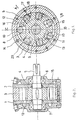
- the motor comprises a stator consisting of the flanges 1 and 2, here produced in two parts, and of a stator ring 3.
- the rotor 4 is fixed on the shaft 5, which can rotate in the stator by means of the bearings 6 and 7.
- the rotor which rotates in the direction of the arrow, has seven grooves 8, guiding seven rollers 9, 10 and 11.
- the two intake ports 12 and 13 are located in the flange 1 and the two exhaust ports 14 and 15 in the flange 2.
- the roller 10 In the represented position of the rotor, the roller 10, at the end of the motor period, is about to open the exhaust port 14, and the pipe face 16 of its groove is about to close the port light 'admission 12; the roller 9 is about to become a motor and the intake port 12 already feeds the expanding working chamber 17 through the open channel 18 provided in the pipe face of its groove.
- the roller 11, applied to the thrust face 19 of its groove is in full period of movement.
- the stator curve 20 is here a Polygon P2 profile.
Landscapes
- Engineering & Computer Science (AREA)
- Mechanical Engineering (AREA)
- General Engineering & Computer Science (AREA)
- Hydraulic Motors (AREA)
- Press Drives And Press Lines (AREA)
Claims (7)
Applications Claiming Priority (2)
| Application Number | Priority Date | Filing Date | Title |
|---|---|---|---|
| FR8408299A FR2564528B1 (fr) | 1984-05-21 | 1984-05-21 | Moteur volumetrique a rouleaux |
| FR8408299 | 1984-05-21 |
Publications (2)
| Publication Number | Publication Date |
|---|---|
| EP0168268A1 EP0168268A1 (de) | 1986-01-15 |
| EP0168268B1 true EP0168268B1 (de) | 1988-07-20 |
Family
ID=9304435
Family Applications (1)
| Application Number | Title | Priority Date | Filing Date |
|---|---|---|---|
| EP85400864A Expired EP0168268B1 (de) | 1984-05-21 | 1985-05-03 | Rollenverdrängungsmaschine |
Country Status (7)
| Country | Link |
|---|---|
| US (1) | US4692105A (de) |
| EP (1) | EP0168268B1 (de) |
| JP (1) | JPH0612047B2 (de) |
| CA (1) | CA1237602A (de) |
| DE (1) | DE3563867D1 (de) |
| FR (1) | FR2564528B1 (de) |
| NO (1) | NO161233C (de) |
Families Citing this family (15)
| Publication number | Priority date | Publication date | Assignee | Title |
|---|---|---|---|---|
| FI87601C (fi) * | 1991-01-16 | 1993-01-25 | Perttu Vaehaesalo | Hydraulmotor |
| FR2683001B1 (fr) * | 1991-10-23 | 1994-02-04 | Andre Leroy | Machine volumetrique axiale. |
| JPH08312485A (ja) * | 1995-05-22 | 1996-11-26 | Sanshin Ind Co Ltd | 船外機用エンジンの燃料噴射装置 |
| NL1007613C2 (nl) | 1997-10-21 | 1999-04-23 | Grup Ir Arnold Willem Josephus | Trillingsvrije rollenwiekmotor en rollenwiekpomp. |
| US6920946B2 (en) * | 2001-09-27 | 2005-07-26 | Kenneth D. Oglesby | Inverted motor for drilling rocks, soils and man-made materials and for re-entry and cleanout of existing wellbores and pipes |
| KR20020074085A (ko) * | 2002-02-08 | 2002-09-28 | 현경열 | 유체 펌프 및 모터 |
| US6857862B2 (en) | 2003-05-01 | 2005-02-22 | Sauer-Danfoss Inc. | Roller vane pump |
| US8388322B2 (en) * | 2007-10-30 | 2013-03-05 | Fluid Control Products, Inc. | Electronic fuel pump |
| US8056251B1 (en) | 2009-09-21 | 2011-11-15 | Regency Technologies Llc | Top plate alignment template device |
| CN102678544B (zh) * | 2012-06-14 | 2014-10-01 | 周震贤 | 多滚子压缩机 |
| CN103147908B (zh) * | 2013-02-28 | 2015-08-19 | 河南科技大学 | 一种液压马达 |
| JP5580443B1 (ja) * | 2013-03-13 | 2014-08-27 | 登 井上 | モーター |
| EP3369929B1 (de) * | 2017-03-03 | 2019-04-24 | PistonPower ApS | Druckverstärker |
| CA3091811A1 (en) | 2019-03-06 | 2020-09-06 | Gartech, Llc | Hydraulic assembly device, system, and method |
| CN113503128B (zh) * | 2021-07-12 | 2022-01-04 | 中国地质大学(北京) | 全金属同心强制配流容积式井下马达 |
Citations (2)
| Publication number | Priority date | Publication date | Assignee | Title |
|---|---|---|---|---|
| US2826179A (en) * | 1954-08-02 | 1958-03-11 | Airway Products Inc | Hydraulic motor |
| GB2028430A (en) * | 1978-08-12 | 1980-03-05 | Bosch Gmbh Robert | Rotary positive-displacement fluidmachines |
Family Cites Families (18)
| Publication number | Priority date | Publication date | Assignee | Title |
|---|---|---|---|---|
| US856317A (en) * | 1907-01-02 | 1907-06-11 | Edward Towlson | Rotary motor. |
| FR844907A (fr) * | 1938-10-18 | 1939-08-04 | L Outil R B V Sa | Pompe hydraulique rotative, reversible en moteur |
| US2241607A (en) * | 1939-12-08 | 1941-05-13 | Frank C Long | Machine for evacuating and exerting pressure on fluids |
| US2628568A (en) * | 1946-04-26 | 1953-02-17 | Ellipse Corp | High-pressure pump |
| FR1198698A (fr) * | 1957-04-08 | 1959-12-09 | Hobourn Eaton Mfg Co Ltd | Pompe rotative, notamment pour véhicules automobiles |
| US3009421A (en) * | 1957-07-11 | 1961-11-21 | Thompson Ramo Wooldridge Inc | Slipper type transmission pump |
| US3066608A (en) * | 1960-11-22 | 1962-12-04 | William T Livermore | Multiple ported transmission pump |
| LU45341A1 (de) * | 1963-02-05 | 1964-04-01 | ||
| FR1438146A (fr) * | 1965-07-06 | 1966-05-06 | Pompe rotative | |
| US3402672A (en) * | 1966-04-21 | 1968-09-24 | Hypro Inc | Roller pump assembly |
| US3542498A (en) * | 1968-09-23 | 1970-11-24 | Hypro Inc | Roller pump |
| US3588297A (en) * | 1968-09-26 | 1971-06-28 | Monogram Ind Inc | Tandem motor assembly |
| US3567350A (en) * | 1969-01-15 | 1971-03-02 | Sperry Rand Corp | Power transmission |
| FR2076575A5 (de) * | 1970-01-20 | 1971-10-15 | Lear Siegler Inc | |
| US3718411A (en) * | 1971-09-14 | 1973-02-27 | Sundstrand Corp | Hydraulic motor |
| US3740954A (en) * | 1972-03-20 | 1973-06-26 | Motorola Inc | Variable speed hydraulic drive mechanism |
| JPS5012546A (de) * | 1973-05-19 | 1975-02-08 | ||
| US4105377A (en) * | 1974-10-15 | 1978-08-08 | William Mayall | Hydraulic roller motor |
-
1984
- 1984-05-21 FR FR8408299A patent/FR2564528B1/fr not_active Expired
-
1985
- 1985-05-03 DE DE8585400864T patent/DE3563867D1/de not_active Expired
- 1985-05-03 EP EP85400864A patent/EP0168268B1/de not_active Expired
- 1985-05-09 CA CA000481202A patent/CA1237602A/fr not_active Expired
- 1985-05-14 US US06/733,807 patent/US4692105A/en not_active Expired - Lifetime
- 1985-05-20 NO NO852008A patent/NO161233C/no not_active IP Right Cessation
- 1985-05-21 JP JP60109191A patent/JPH0612047B2/ja not_active Expired - Lifetime
Patent Citations (2)
| Publication number | Priority date | Publication date | Assignee | Title |
|---|---|---|---|---|
| US2826179A (en) * | 1954-08-02 | 1958-03-11 | Airway Products Inc | Hydraulic motor |
| GB2028430A (en) * | 1978-08-12 | 1980-03-05 | Bosch Gmbh Robert | Rotary positive-displacement fluidmachines |
Also Published As
| Publication number | Publication date |
|---|---|
| EP0168268A1 (de) | 1986-01-15 |
| JPH0612047B2 (ja) | 1994-02-16 |
| FR2564528A1 (fr) | 1985-11-22 |
| DE3563867D1 (en) | 1988-08-25 |
| JPS60259701A (ja) | 1985-12-21 |
| CA1237602A (fr) | 1988-06-07 |
| NO161233C (no) | 1989-07-19 |
| US4692105A (en) | 1987-09-08 |
| NO161233B (no) | 1989-04-10 |
| FR2564528B1 (fr) | 1986-09-19 |
| NO852008L (no) | 1985-11-22 |
Similar Documents
| Publication | Publication Date | Title |
|---|---|---|
| EP0168268B1 (de) | Rollenverdrängungsmaschine | |
| FR2914372A1 (fr) | Pompe equilibree a palettes a cylindree variable avec joints d'etancheite de face flottants et joints d'etancheite de pa lette sollicites | |
| FR2572470A1 (fr) | Pompe a palettes a ecoulement reversible. | |
| EP0627042B1 (de) | Verdrängermaschine insbesondere viertaktmotor | |
| EP1466093A1 (de) | Radialkolbenhydraulikmotor | |
| FR2617537A1 (fr) | Dispositif de transmission de puissance a fluide | |
| EP3045656B1 (de) | Mehrfunktionsrotationsmaschine mit verformbarem rhombus | |
| FR2588322A1 (fr) | Machine hydraulique de structure modulaire | |
| EP0086719B1 (de) | Maschine zum Ansaugen und Abgeben eines Fluidums | |
| EP3686422A1 (de) | Turbine mit hydrostatischer drehung | |
| CA1189388A (fr) | Dispositif hydraulique rotatif convertisseur et repartiteur a multi-cylindrees synchronisees | |
| FR2561315A1 (fr) | Machine hydraulique | |
| EP1216358B1 (de) | Spiralverdichter | |
| FR2591286A1 (fr) | Machine volumetrique a palette(s). | |
| EP1012479A1 (de) | Turbinenpumpe mit verbessertem wirkungsgrad insbesondere für fahrzeugkraftstoffbehälter | |
| BE514842A (de) | ||
| WO2021084176A1 (fr) | Moteur à combustion interne | |
| CA2192495C (fr) | Moteur a explosion avec des pistons rotatifs | |
| CH315425A (fr) | Machine rotative réversible | |
| BE659088A (de) | ||
| BE462076A (de) | ||
| BE721913A (de) | ||
| CH448752A (fr) | Machine volumétrique rotative | |
| FR2505415A1 (fr) | Pompe monovis equilibree a forte puissance massique | |
| BE566105A (de) |
Legal Events
| Date | Code | Title | Description |
|---|---|---|---|
| PUAI | Public reference made under article 153(3) epc to a published international application that has entered the european phase |
Free format text: ORIGINAL CODE: 0009012 |
|
| AK | Designated contracting states |
Designated state(s): BE DE FR GB IT NL |
|
| 17P | Request for examination filed |
Effective date: 19860206 |
|
| 17Q | First examination report despatched |
Effective date: 19861020 |
|
| ITF | It: translation for a ep patent filed | ||
| GRAA | (expected) grant |
Free format text: ORIGINAL CODE: 0009210 |
|
| AK | Designated contracting states |
Kind code of ref document: B1 Designated state(s): BE DE FR GB IT NL |
|
| GBT | Gb: translation of ep patent filed (gb section 77(6)(a)/1977) | ||
| REF | Corresponds to: |
Ref document number: 3563867 Country of ref document: DE Date of ref document: 19880825 |
|
| PLBE | No opposition filed within time limit |
Free format text: ORIGINAL CODE: 0009261 |
|
| STAA | Information on the status of an ep patent application or granted ep patent |
Free format text: STATUS: NO OPPOSITION FILED WITHIN TIME LIMIT |
|
| 26N | No opposition filed | ||
| ITTA | It: last paid annual fee | ||
| REG | Reference to a national code |
Ref country code: GB Ref legal event code: IF02 |
|
| PGFP | Annual fee paid to national office [announced via postgrant information from national office to epo] |
Ref country code: BE Payment date: 20020506 Year of fee payment: 18 |
|
| PGFP | Annual fee paid to national office [announced via postgrant information from national office to epo] |
Ref country code: GB Payment date: 20020508 Year of fee payment: 18 |
|
| PGFP | Annual fee paid to national office [announced via postgrant information from national office to epo] |
Ref country code: FR Payment date: 20020530 Year of fee payment: 18 |
|
| PGFP | Annual fee paid to national office [announced via postgrant information from national office to epo] |
Ref country code: NL Payment date: 20020531 Year of fee payment: 18 |
|
| PG25 | Lapsed in a contracting state [announced via postgrant information from national office to epo] |
Ref country code: GB Free format text: LAPSE BECAUSE OF NON-PAYMENT OF DUE FEES Effective date: 20030503 |
|
| PG25 | Lapsed in a contracting state [announced via postgrant information from national office to epo] |
Ref country code: BE Free format text: LAPSE BECAUSE OF NON-PAYMENT OF DUE FEES Effective date: 20030531 |
|
| PGFP | Annual fee paid to national office [announced via postgrant information from national office to epo] |
Ref country code: DE Payment date: 20030910 Year of fee payment: 19 |
|
| BERE | Be: lapsed |
Owner name: *LEROY ANDRE Effective date: 20030531 |
|
| PG25 | Lapsed in a contracting state [announced via postgrant information from national office to epo] |
Ref country code: NL Free format text: LAPSE BECAUSE OF NON-PAYMENT OF DUE FEES Effective date: 20031201 |
|
| GBPC | Gb: european patent ceased through non-payment of renewal fee |
Effective date: 20030503 |
|
| PG25 | Lapsed in a contracting state [announced via postgrant information from national office to epo] |
Ref country code: FR Free format text: LAPSE BECAUSE OF NON-PAYMENT OF DUE FEES Effective date: 20040130 |
|
| NLV4 | Nl: lapsed or anulled due to non-payment of the annual fee |
Effective date: 20031201 |
|
| REG | Reference to a national code |
Ref country code: FR Ref legal event code: ST |
|
| PG25 | Lapsed in a contracting state [announced via postgrant information from national office to epo] |
Ref country code: DE Free format text: LAPSE BECAUSE OF NON-PAYMENT OF DUE FEES Effective date: 20041201 |