EP0168497A1 - Miroir anti-eblouissant - Google Patents
Miroir anti-eblouissant Download PDFInfo
- Publication number
- EP0168497A1 EP0168497A1 EP84900537A EP84900537A EP0168497A1 EP 0168497 A1 EP0168497 A1 EP 0168497A1 EP 84900537 A EP84900537 A EP 84900537A EP 84900537 A EP84900537 A EP 84900537A EP 0168497 A1 EP0168497 A1 EP 0168497A1
- Authority
- EP
- European Patent Office
- Prior art keywords
- dazzle
- free portion
- reflection mirror
- free
- electrode layers
- Prior art date
- Legal status (The legal status is an assumption and is not a legal conclusion. Google has not performed a legal analysis and makes no representation as to the accuracy of the status listed.)
- Granted
Links
Images



Classifications
-
- G—PHYSICS
- G02—OPTICS
- G02B—OPTICAL ELEMENTS, SYSTEMS OR APPARATUS
- G02B7/00—Mountings, adjusting means, or light-tight connections, for optical elements
- G02B7/18—Mountings, adjusting means, or light-tight connections, for optical elements for prisms; for mirrors
- G02B7/182—Mountings, adjusting means, or light-tight connections, for optical elements for prisms; for mirrors for mirrors
- G02B7/1822—Mountings, adjusting means, or light-tight connections, for optical elements for prisms; for mirrors for mirrors comprising means for aligning the optical axis
-
- B—PERFORMING OPERATIONS; TRANSPORTING
- B60—VEHICLES IN GENERAL
- B60R—VEHICLES, VEHICLE FITTINGS, OR VEHICLE PARTS, NOT OTHERWISE PROVIDED FOR
- B60R1/00—Optical viewing arrangements; Real-time viewing arrangements for drivers or passengers using optical image capturing systems, e.g. cameras or video systems specially adapted for use in or on vehicles
- B60R1/02—Rear-view mirror arrangements
- B60R1/08—Rear-view mirror arrangements involving special optical features, e.g. avoiding blind spots, e.g. convex mirrors; Side-by-side associations of rear-view and other mirrors
- B60R1/083—Anti-glare mirrors, e.g. "day-night" mirrors
- B60R1/088—Anti-glare mirrors, e.g. "day-night" mirrors using a cell of electrically changeable optical characteristic, e.g. liquid-crystal or electrochromic mirrors
Definitions
- the invention relates to a dazzle-free reflection mirror of a vehicle and the manufacturing method thereof.
- the dazzle-free reflection mirror which may be used as an inner mirror or an outer mirror of the vehicle, has an electro-optical element of which transparency is electrically controlled by applying an electric field thereto.
- a dazzle-free reflection mirror has a dazzle-free portion, which comprises an electro-optical element such as a liquid crystal or an electrochromic, on the whole mirror surface for effectuating a dazzle-free operation.
- an electro-optical element such as a liquid crystal or an electrochromic
- the dazzling which the driver of the vehicle feels is not caused by light reflected on the whole mirror surface but caused by light reflected on limited area of the mirror surface.
- the image of following-vehicle headlights is usually seen in a lower part of the mirror surface.
- the inventors have found the above-mentioned facts and conceived that such dazzling caught by drivers can be prevented by putting the only lower part of the mirror surface into the dazzle-free condition and that the appearance of the following vehicle can be clearly imaged on the rest part of the mirror surface, which is constructed as a non-dazzle-free portion.
- a dazzle-free reflection mirror having an electro-optical element, of which transparency is changed by applying an electric field thereto is characterized in that a dazzle-free portion including the electro-optical element is arranged at a lower part of a mirror surface to effectuate a dazzle-free operation while a non-dazzle-free portion is arranged at the rest part of the mirror surface not to effectuate the dazzle-free-operation.
- the above-mentioned structure comprising the dazzle-free portion and the non-dazzle-free portion is advantageous in that the dazzling caught by the driver can be prevented by shielding light from following-vehicle headlights at night by operation of the dazzle-free portion arranged at the lower part of the mirror surface and that the appearance of the following vehicle can be clearly imaged in the non-dazzle-free portion at the rest part of the mirror surface even during the dazzle-free operation.
- the second invention relates to the manufacturing method of the dazzle-free reflection mirror comprising the first step for uniformly forming an electrode layer on each one surface of a pair of transparent substrates, the second step for respectively forming an orientation film on the electrode layers, the third step for opposing the pair of transparent substrates to each other to form a cell for filling therein liquid crystal and for sealing the surrounding peripheries of the substrates, and the fourth step for supporting the pair of transparent substrates forming the cell with a frame, characterized by a further step-following said first step for insulating at least one of said electrode layers in order to form a non-dazzle-free portion so that an electric field is not applied to the associated liquid crystal.
- This manufacturing method is advantageous in that the dazzle-free portion and the non-dazzle-free portion of the dazzle-free reflection mirror according to the first invention can be manufactured easily and integrally.
- Fig. 1 is a front view of a dazzle-free reflection mirror according to the first embodiment and Fig. 2 is a cross-sectional view thereof.
- This dazzle-free reflection mirror has a frame 2 and a supporting element 1 for supporting the frame 2.
- the frame 2 holds a liquid crystal element 50 therein.
- the liquid crystal element 50 comprises a dazzle-free portion 40 occupying a lower two-thirds portion from the bottom end 40a, which may occupy a lower portion between a half and five-sixths, and a non-dazzle-free portion 30 in the rest portion on the mirror surface.
- the dazzle-free portion 40 and the non-dazzle-free portion 30 are constructed as a unitary body.
- the non-dazzle-free portion 30 does not effectuate a dazzle-free operation because an electric field is not applied to the liquid crystal therein.
- the liquid crystal element 50 includes a transparent glass substrate 3a, a transparent electrode layer 4a made of indium tim oxide (ITO), an alignment film 5a for orientating the liquid crystal parallelly, a liquid crystal layer 6 made of a nematic liquid crystal acting as a DSM (dynamic scattering mode) liquid crystal, a transparent electrode layer 4b, a transparent glass substrate 3b, and a semitransparent or a translucent mirror layer 8, being stacked in this order from the light incident side.
- ITO indium tim oxide
- DSM dynamic scattering mode
- the dazzle-free portion 40 is so arranged that the transparency thereof is electrically controlled by appling a voltage to the electrode layers 4a and 4b so that the liquid crystal layer therein moves into the dynamic scattering mode.
- the thicknesses of the transparent electrodes 4a and 4b and orientation films 5a and 5b are respectively 1000A.
- the thickness of the liquid crystal layer 6 is 10 ⁇ m.
- the translucent mirror layer 8 is made of aluminum, of which thickness is 300A.
- the transparent electrode layers are not respectively formed on the transparent glass substrates 3a and 3b so that the electric field is not applied to the liquid crystal therein.
- a photo diode 10 as a photo sensor, for detecting light incident through the non-dazzle-free portion 30 is located behind the liquid crystal element 50.
- the photo diode 10 is attached on a base plate 91 supporting a driving circuit 9.
- the driving circuit 9 drives the liquid crystal element 50 to put the dazzle-free portion 40 into the dazzle-free condition during the photo diode 10 detects that the intensity of light-incident through the non-dazzle-free portion 30 is higher than a predetermined value.
- the driving circuit 9 is supplied with voltage through voltage supply lines 92 from a battery mounted on the vehicle.
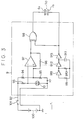
- the circuit including the driving circuit 9 is shown in Fig. 3.
- a light switch 101 is turned on, the driving circuit 9 to which the voltage is supplied from the battery becomes operative.
- the photo diode 10 receives light of a high- level intensity, the voltage of an inverting input terminal of a comparator 97 becomes low.
- the output voltage of the comparator 97 becomes high, thereby being applied to the input terminal of an exclusive-OR circuit 98.
- the oscillation signal of an oscillation circuit which comprises C-MOS inverter circuits 911, 912 and 913, resistors 99 and 910 and a capacitor 911, is respectively applied to the other input terminal of the exclusive-OR circuit 98-and the transparent electrode layer--4b.
- the output of the comparator 97 becomes high, the output voltage of the exclusive-OR circuit 98 becomes in the opposite phase relation with the oscillation signal. Accordingly, an alternating current voltage is applied between the transparent electrode layers 4a and 4b of the liquid crystal element 50, so that the dazzle-free portion 40 is put into the dazzle-free condition.
- the output voltage of the comparator 97 becomes low so that the output voltage of the exclusive-OR circuit 98 becomes in the same phase relation with the oscillation signal. Accordingly, the voltages applied to the transparent electrode layers 4a and 4b become in the same relation, so that no voltage is applied to the liquid crystal layer 6. As a result, the dazzle-free portion 40 of the liquid crystal element 50 is not put into the dazzle-free condition.
- a resistor 96 provides the comparator 97 with a hysteresis function.
- the comparator 97, the exclusive-OR circuit 98, and c-MOS invertor circuits 911, 912 and 913 are supplied with the voltage through the voltage supply lines 92 from the battery thereby to become operative.
- the transparent electrode layers 4a and 4b can be made of tin dioxide (Sn0 2 ) or titanium dioxide (ti0 2 ) instead of the ITO.
- the ratio between transparency and reflectivity thereof can be set appropriately by vapor-depositing metal or nonmetal film of an optional thickness to the transparent glass substrate 3b.
- zinc sulfide (ZnS) or ceric oxide (Ce0 2 ) of which film thickness is equal to a quarter of light wave-length can be used as the translucent layer 8.
- ZincS zinc sulfide
- Ce0 2 ceric oxide
- Aluminum, silver, chromium or gold can be likewise used as the translucent layer 8.
- the dazzle-free portion 40 and non-dazzle-free portion .30 are manufactured by not forming transparent electrode layers at a region corresponding to the non-dazzle-free portion 30.
- the non-dazzle-free portion 30 may be constructed by eliminating only a part of one of the transparent electrode layers, which region corresponds to the non-dazzle-free portion 30 as shown in Fig. 4.
- the dazzle-free reflection mirror according to the second embodiment is, as shown in Fig. 5, so arranged that the dazzle-free portion 40 and the non-dazzle-free portion 30 are constructed by forming slits 50a and 50b in the transparent electrode layers 4a and 4b, respectively.
- the electric field is applied to only the liquid crystal layer 6 in the dazzle-free portion 40 to effectuate the dazzle-free operation.
- Fig. 6 is a cross-sectional view of the dazzle-free reflection mirror according to the third embodiment.
- a transparent insulation film 60 is formed on a part of the transparent electrode layer 4b, which region corresponds to the non-dazzle-free portion 30.
- the transparent insulation film 60 can be formed by vacuum-depositing or sputtering aluminum oxide (Al 2 O 3 ), silicon monoxide (SiO), silicon dioxide (Si0 2 ), titanium dioxide (Ti0 2 ) or magnesium defluoride (MgF 2 ), or can be formed by anodic-oxidating the electrode formed by aluminum.
- the translucent mirror layer 8 may be provided, a complete reflection mirror layer may be provided instead of the translucent mirror layer 8 in case the photo diode 10 is provided anywhere else than behind the reflection mirror layer. Further, the electrode layer 4b may be used as the translucent mirror layer or the complete reflection mirror layer.
- Fig. 7 is a cross-sectional view of the reflection mirror according to this embodiment.
- the dazzle-free portion 40 and non-dazzle-free portion 30 are separated from each other by a seal material 70.
- the non-dazzle-free portion 30 comprises non-electric conductive- material between the-electrode layers 4a and 4b.
- the non-electric conductive material the air, silicon oil, silicon rubber, silicon resin, or epoxy resin can be used.
- Fig. 8 is a cross-sectional view of the reflection mirror according to this embodiment.
- the non-dazzle-free portion 30 comprises a translucent mirror layer 8a directly formed on the transparent glass substrate 3a.
- the complete reflection mirror layer 8 is formed on the transparent glass substrate 3b by vacuum-depositing aluminium of which thickness is 300A.
- the translucent mirror layer 8a is formed on the transparent glass substrate 3b in the above-described non-dazzle-free portion 30, a complete reflection mirror layer may be formed instead of the translucent mirror layer 8a in case the photo diode 10 is provided anywhere else than behind the reflection mirror layer.
- Figs. 9 and 10 are respectively a cross-sectional view and a front view of the reflection mirror of this embodiment.
- the liquid crystal element 50 is the same structure as that shown in Fig. 4.
- a display device 80 composed of LEDs is provided behind the non-dazzle-free portion 30.
- the display device 80 displays time at display portion 82 shown in Fig. 10.
- This embodiment is characterized in that the displayed time on the display device 80 behind the liquid crystal element 50 can be seen through the non-dazzle-free portion 30 since the transparency of the non-dazzle-free portion 30 is not changed.
- Fig. 11 is a flow chart showing a series of processing steps according to this embodiment. This embodiment is characterized in that portion of the transparent electrode layers are eliminated by etching to form the non-dazzle-free portion 30 as shown in Fig. 2.
- soda glass is cut in a shape of transparent glass substrate.
- a transparent conductive film is formed on the glass substrate as an electrode.
- the transparent conductive film is made of indium tin oxide in which weight percentage ratio between In 2 0 3 and SnO 2 is 95:5 and is formed to film thickness of 1000A by an electron beam deposition under 350°C - 400°C and oxygen partial pressure of 1 ⁇ 10 -2 pa - 5 ⁇ 10 -2 Pa.
- acid-resistant resist ink is printed on the transparent conductive film over a whole range corresponding to the dazzle-free portion 40 so that a masking is provided.
- the substrate with the transparent conductive film is dipped in a fluid solution mixture of concentrated hydrochroric acid and water in 1:1 ratio under temperature of 45°C for two minutes so that surrounding portions of the transparent conductive film corresponding to the non-dazzle-free portion 30 is removed therefrom.
- the resist ink is removed by the use of organic solvent, trichloroethylene.
- alignment processing is done to align the liquid crystal parallelly.
- polyimide solution is slushed by a spinner at 3500 rpm and thereafter the substrate is maintained at temperatures of 300°C for 30 minutes and 400°C for 30 minutes and fired thereby to form an alignment film on the conductive film.
- rubbing the alignment film is done by the use of chemical fiber cloth to provide alignment of liquid crystal filled in later.
- sealing material is printed on side portions by the use of epoxy resin.
- glass fiber particles in particle diameter of 10 um are spread as spacers on the alignment film.
- a pair of glass substrates, each being processed as above-described are put one upon another in parallel and maintained under temperature of 100°C for 2 hours for bonding so that a liquid crystal cell is provided.
- chromium film is vapor-deposited on the other end surface of one of the transparent glass substrates under the condition that the substrate is maintained under temperature of 100°C to form the translucent mirror layer 8 of 300A.
- liquid crystal is filled in an inner space of the liquid crystal cell by a decompressed injection process.
- a step 122 an injection opening is sealed with epoxy adhesive.
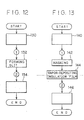
- a modified manufacturing method will be explained with reference to Fig. 12 showing a flow chart of a series of processing steps according to the modified embodintent.
- a step 130 corresponds to the steps 100 and 102 shown in Fig. 11.
- a slit formed in the transparent conductive film to separate the non-dazzle-free portion 40 from the dazzle-free portion 30 by the same eliminating means as shown at the steps 104 and 108.
- the slit insulates the separated transparent conductive films from each other.
- the slit may be formed by cutting with the edge of a steel blade or a laser instead of the etching.
- a step 134 corresponds to the steps 110 to 122 shown in Fig. 11.
- a step 140 corresponds to the steps 100 and 102 shown in Fig. 11.
- a whole range corresponding to the dazzle-free portion 40 is masked by metal.
- an insulation film is formed by vapor-depositing SiO on a surface of the transparent conductive film over a whole range corresponding to the non-dazzle-free portion 30.
- the non-dazzle-free portion 30 is formed.
- a step 146 corresponds to the steps 110 to 122 shown in Fig. 11.
- the liquid crystal element for the dazzle-free reflection mirror is manufactured in accordance with one of the above-mentioned manufacturing methods.
- the alignment processing may be done by oblique vapor-depositing of SiO (incident angle: 80°, thickness: 500A).
- the mirror layer may be formed on the substrate by vapor-depositing- aluminum or silver under temperature of 100°C so that the film thickness becomes 300A or 250A, respectively.
- the dazzle-free reflection mirror according to the present invention can be applied to the inner mirror or the outer mirror of a vehicle.
Landscapes
- Physics & Mathematics (AREA)
- Engineering & Computer Science (AREA)
- General Physics & Mathematics (AREA)
- Optics & Photonics (AREA)
- Chemical & Material Sciences (AREA)
- Crystallography & Structural Chemistry (AREA)
- Multimedia (AREA)
- Mechanical Engineering (AREA)
- Optical Elements Other Than Lenses (AREA)
- Liquid Crystal (AREA)
Abstract
Applications Claiming Priority (2)
| Application Number | Priority Date | Filing Date | Title |
|---|---|---|---|
| JP58248579A JPS60143301A (ja) | 1983-12-29 | 1983-12-29 | 防眩型反射鏡とその製造方法 |
| JP248579/83 | 1983-12-29 |
Publications (3)
| Publication Number | Publication Date |
|---|---|
| EP0168497A1 true EP0168497A1 (fr) | 1986-01-22 |
| EP0168497A4 EP0168497A4 (fr) | 1986-06-05 |
| EP0168497B1 EP0168497B1 (fr) | 1989-04-12 |
Family
ID=17180224
Family Applications (1)
| Application Number | Title | Priority Date | Filing Date |
|---|---|---|---|
| EP84900537A Expired EP0168497B1 (fr) | 1983-12-29 | 1984-01-19 | Miroir anti-eblouissant |
Country Status (6)
| Country | Link |
|---|---|
| US (1) | US4721364A (fr) |
| EP (1) | EP0168497B1 (fr) |
| JP (1) | JPS60143301A (fr) |
| AU (1) | AU2496184A (fr) |
| DE (1) | DE3477696D1 (fr) |
| WO (1) | WO1985003136A1 (fr) |
Cited By (2)
| Publication number | Priority date | Publication date | Assignee | Title |
|---|---|---|---|---|
| GB2297071A (en) * | 1995-01-17 | 1996-07-24 | Murakami Keimeido Co Ltd | Vehicle anti-glare and wide visibility rearview mirror |
| EP0729864A1 (fr) * | 1995-03-02 | 1996-09-04 | Gentex Corporation | Rétroviseur pour véhicules |
Families Citing this family (88)
| Publication number | Priority date | Publication date | Assignee | Title |
|---|---|---|---|---|
| JPS6159301A (ja) * | 1984-08-30 | 1986-03-26 | Nippon Denso Co Ltd | 防眩型反射鏡制御装置 |
| US5153760A (en) * | 1990-06-13 | 1992-10-06 | Ahmed Adel A A | Oscillating photovoltaic optical shutter for reflective display |
| US5151824A (en) * | 1990-11-26 | 1992-09-29 | Donnelly Corporation | Vehicular outside mirror assembly |
| US5446576A (en) * | 1990-11-26 | 1995-08-29 | Donnelly Corporation | Electrochromic mirror for vehicles with illumination and heating control |
| US5168378A (en) * | 1992-02-10 | 1992-12-01 | Reliant Laser Corporation | Mirror with dazzle light attenuation zone |
| US5285060A (en) * | 1992-12-15 | 1994-02-08 | Donnelly Corporation | Display for automatic rearview mirror |
| US6276821B1 (en) * | 1992-12-16 | 2001-08-21 | Donnelly Corporation | Vehicle exterior mirror system with signal light |
| US5910854A (en) | 1993-02-26 | 1999-06-08 | Donnelly Corporation | Electrochromic polymeric solid films, manufacturing electrochromic devices using such solid films, and processes for making such solid films and devices |
| US5322996A (en) * | 1993-04-28 | 1994-06-21 | Reliant Laser Corporation | Mirror with dynamic dazzle light attenuation zone |
| US5668663A (en) | 1994-05-05 | 1997-09-16 | Donnelly Corporation | Electrochromic mirrors and devices |
| US6019475A (en) | 1994-09-30 | 2000-02-01 | Donnelly Corporation | Modular rearview mirror assembly including an electronic control module |
| US5659423A (en) * | 1994-09-30 | 1997-08-19 | Donnelly Corporation | Modular variable reflectance mirror assembly |
| US5930047A (en) * | 1995-04-21 | 1999-07-27 | Xelux Holding Ag | Anti-glare device |
| US6891563B2 (en) | 1996-05-22 | 2005-05-10 | Donnelly Corporation | Vehicular vision system |
| US5788357A (en) * | 1996-08-28 | 1998-08-04 | K. W. Muth Company, Inc. | Mirror assembly |
| US6045243A (en) * | 1996-08-28 | 2000-04-04 | K.W. Muth Company, Inc. | Mirror assembly |
| US6172613B1 (en) | 1998-02-18 | 2001-01-09 | Donnelly Corporation | Rearview mirror assembly incorporating vehicle information display |
| US8294975B2 (en) | 1997-08-25 | 2012-10-23 | Donnelly Corporation | Automotive rearview mirror assembly |
| US6326613B1 (en) | 1998-01-07 | 2001-12-04 | Donnelly Corporation | Vehicle interior mirror assembly adapted for containing a rain sensor |
| US6124886A (en) | 1997-08-25 | 2000-09-26 | Donnelly Corporation | Modular rearview mirror assembly |
| ES1038631Y (es) * | 1997-10-30 | 1999-01-01 | Vidal Domingo Luis | Sistema anti-deslumbramiento para espejos retrovisores. |
| US8288711B2 (en) | 1998-01-07 | 2012-10-16 | Donnelly Corporation | Interior rearview mirror system with forwardly-viewing camera and a control |
| US6445287B1 (en) | 2000-02-28 | 2002-09-03 | Donnelly Corporation | Tire inflation assistance monitoring system |
| US6329925B1 (en) | 1999-11-24 | 2001-12-11 | Donnelly Corporation | Rearview mirror assembly with added feature modular display |
| US6477464B2 (en) | 2000-03-09 | 2002-11-05 | Donnelly Corporation | Complete mirror-based global-positioning system (GPS) navigation solution |
| US6693517B2 (en) | 2000-04-21 | 2004-02-17 | Donnelly Corporation | Vehicle mirror assembly communicating wirelessly with vehicle accessories and occupants |
| US6005724A (en) * | 1998-10-05 | 1999-12-21 | K. W. Muth Company, Inc. | Mirror coating, mirror utilizing same, and a mirror assembly |
| US6257746B1 (en) | 1998-11-03 | 2001-07-10 | K. W. Muth Company, Inc. | Signalling assembly |
| US6301794B1 (en) * | 1999-05-27 | 2001-10-16 | Johnson Controls, Inc. | Vehicle compass system with continuous automatic calibration |
| US8066415B2 (en) | 1999-06-17 | 2011-11-29 | Magna Mirrors Of America, Inc. | Exterior mirror vision system for a vehicle |
| US7370983B2 (en) | 2000-03-02 | 2008-05-13 | Donnelly Corporation | Interior mirror assembly with display |
| WO2004058540A2 (fr) * | 2002-12-20 | 2004-07-15 | Donnelly Corporation | Systeme d'accessoire pour vehicule |
| WO2001064481A2 (fr) | 2000-03-02 | 2001-09-07 | Donnelly Corporation | Systeme de miroir video integrant un module accessoire |
| US7195381B2 (en) | 2001-01-23 | 2007-03-27 | Donnelly Corporation | Vehicle interior LED lighting system |
| US7167796B2 (en) | 2000-03-09 | 2007-01-23 | Donnelly Corporation | Vehicle navigation system for use with a telematics system |
| US7581859B2 (en) | 2005-09-14 | 2009-09-01 | Donnelly Corp. | Display device for exterior rearview mirror |
| US7255451B2 (en) | 2002-09-20 | 2007-08-14 | Donnelly Corporation | Electro-optic mirror cell |
| US7110156B2 (en) | 2002-04-26 | 2006-09-19 | Donnelly Mirrors Limited | Rearview mirror assemblies |
| US6918674B2 (en) | 2002-05-03 | 2005-07-19 | Donnelly Corporation | Vehicle rearview mirror system |
| WO2003105099A1 (fr) | 2002-06-06 | 2003-12-18 | Donnelly Corporation | Systeme de miroir de courtoisie interieur a boussole |
| US7329013B2 (en) | 2002-06-06 | 2008-02-12 | Donnelly Corporation | Interior rearview mirror system with compass |
| US7184190B2 (en) * | 2002-09-20 | 2007-02-27 | Donnelly Corporation | Electro-optic reflective element assembly |
| US7310177B2 (en) | 2002-09-20 | 2007-12-18 | Donnelly Corporation | Electro-optic reflective element assembly |
| US7274501B2 (en) | 2002-09-20 | 2007-09-25 | Donnelly Corporation | Mirror reflective element assembly |
| US7360932B2 (en) * | 2004-06-01 | 2008-04-22 | Donnelly Corporation | Mirror assembly for vehicle |
| US7289037B2 (en) | 2003-05-19 | 2007-10-30 | Donnelly Corporation | Mirror assembly for vehicle |
| US7420756B2 (en) | 2003-05-20 | 2008-09-02 | Donnelly Corporation | Mirror reflective element |
| US7446924B2 (en) * | 2003-10-02 | 2008-11-04 | Donnelly Corporation | Mirror reflective element assembly including electronic component |
| US7308341B2 (en) | 2003-10-14 | 2007-12-11 | Donnelly Corporation | Vehicle communication system |
| US7008091B2 (en) | 2003-12-18 | 2006-03-07 | K.W. Muth Company, Inc. | Electromagnetic radiation assembly |
| US7400435B2 (en) | 2005-01-19 | 2008-07-15 | Donnelly Corporation | Mirror assembly with heater element |
| US7241037B2 (en) * | 2005-03-23 | 2007-07-10 | K.W. Muth Company | Signaling assembly |
| EP1883855B1 (fr) | 2005-05-16 | 2011-07-20 | Donnelly Corporation | Ensemble de retroviseur de vehicule comportant des informations sur l'element reflecteur |
| US7327321B2 (en) | 2005-06-27 | 2008-02-05 | K.W. Muth Company, Inc. | Electromagnetic radiation assembly |
| US11498487B2 (en) | 2005-07-06 | 2022-11-15 | Magna Mirrors Of America, Inc. | Vehicular exterior mirror system with blind spot indicator |
| US11242009B2 (en) | 2005-07-06 | 2022-02-08 | Donnelly Corporation | Vehicular exterior mirror system with blind spot indicator |
| WO2008051910A2 (fr) | 2006-10-24 | 2008-05-02 | Donnelly Corporation | Dispositif d'affichage pour un rétroviseur |
| WO2007005942A2 (fr) | 2005-07-06 | 2007-01-11 | Donnelly Corporation | Ensemble de retroviseur exterieur pour vehicule equipe d'un indicateur d'angle mort |
| CN101535087B (zh) * | 2005-11-01 | 2013-05-15 | 唐纳利公司 | 具有显示装置的内部后视镜 |
| US11890991B2 (en) | 2006-10-24 | 2024-02-06 | Magna Mirrors Of America, Inc. | Vehicular exterior rearview mirror assembly with blind spot indicator element |
| US7944371B2 (en) | 2007-11-05 | 2011-05-17 | Magna Mirrors Of America, Inc. | Exterior mirror with indicator |
| US7777611B2 (en) * | 2006-11-06 | 2010-08-17 | Donnelly Corporation | Display device for exterior rearview mirror |
| US7748856B2 (en) * | 2007-05-23 | 2010-07-06 | Donnelly Corporation | Exterior mirror element with integral wide angle portion |
| US8154418B2 (en) | 2008-03-31 | 2012-04-10 | Magna Mirrors Of America, Inc. | Interior rearview mirror system |
| US7813023B2 (en) * | 2008-06-09 | 2010-10-12 | Magna Mirrors Of America, Inc. | Electro-optic mirror |
| US9205780B2 (en) | 2010-02-04 | 2015-12-08 | Magna Mirrors Of America, Inc. | Electro-optic rearview mirror assembly for vehicle |
| US9481304B2 (en) | 2010-05-24 | 2016-11-01 | Magna Mirrors Of America, Inc. | Automotive exterior mirror heater control |
| US8988755B2 (en) | 2011-05-13 | 2015-03-24 | Magna Mirrors Of America, Inc. | Mirror reflective element |
| US8736940B2 (en) | 2011-09-30 | 2014-05-27 | Magna Mirrors Of America, Inc. | Exterior mirror with integral spotter mirror and method of making same |
| US8801245B2 (en) | 2011-11-14 | 2014-08-12 | Magna Mirrors Of America, Inc. | Illumination module for vehicle |
| US9216691B2 (en) | 2013-02-25 | 2015-12-22 | Magna Mirrors Of America, Inc. | Exterior mirror with spotter mirror |
| US9815409B2 (en) | 2013-05-09 | 2017-11-14 | Magna Mirrors Of America, Inc. | Rearview vision system for vehicle |
| US9761144B2 (en) | 2014-09-11 | 2017-09-12 | Magna Mirrors Of America, Inc. | Exterior mirror with blind zone indicator |
| US9776569B2 (en) | 2015-01-30 | 2017-10-03 | Magna Mirrors Of America, Inc. | Exterior mirror with heater pad |
| EP3292024A4 (fr) | 2015-05-06 | 2018-06-20 | Magna Mirrors of America, Inc. | Système de vision pour véhicule ayant un système d'alerte et d'affichage de zone aveugle |
| US9659498B2 (en) | 2015-09-28 | 2017-05-23 | Magna Mirrors Of America, Inc. | Exterior mirror assembly with blind zone indicator |
| EP3368374B1 (fr) * | 2015-10-30 | 2023-12-27 | Gentex Corporation | Manette à bascule |
| US10166924B2 (en) | 2016-05-11 | 2019-01-01 | Magna Mirrors Of America, Inc. | Vehicle vision system with display by a mirror |
| US10442360B2 (en) | 2017-03-02 | 2019-10-15 | Magna Mirrors Of America, Inc. | Interior rearview mirror assembly with display and tilt mechanism |
| US20190118717A1 (en) | 2017-10-25 | 2019-04-25 | Magna Mirrors Of America, Inc. | Full mirror display utilizing a trailer camera |
| US10836315B2 (en) | 2017-11-06 | 2020-11-17 | Magna Mirrors Of America, Inc. | Mirror display system with blind spot display |
| US11214199B2 (en) | 2019-06-03 | 2022-01-04 | Magna Mirrors Of America, Inc. | Interior rearview mirror assembly with display and tilt mechanism |
| US11498494B2 (en) | 2019-11-27 | 2022-11-15 | Magna Electronics Inc. | Vehicular camera monitoring system |
| US11572018B2 (en) | 2019-12-27 | 2023-02-07 | Magna Mirrors Of America, Inc. | Vehicular exterior mirror assembly with blind zone indicator including anti-backout connector |
| US11242008B2 (en) | 2020-02-07 | 2022-02-08 | Magna Mirrors Of America, Inc. | Vehicular vision system with center stack display and mirror display for surround view and CMS cameras |
| US12145507B2 (en) | 2020-04-20 | 2024-11-19 | Magna Mirrors Of America, Inc. | Interior rearview mirror assembly with actuator |
| US11884216B2 (en) | 2020-10-16 | 2024-01-30 | Magna Mirrors Of America, Inc. | Vehicular full mirror display system with auxiliary forward and rearward views |
| US11851080B2 (en) | 2021-02-03 | 2023-12-26 | Magna Mirrors Of America, Inc. | Vehicular driver monitoring system with posture detection and alert |
Family Cites Families (20)
| Publication number | Priority date | Publication date | Assignee | Title |
|---|---|---|---|---|
| JPS4835384B1 (fr) * | 1969-08-30 | 1973-10-27 | ||
| JPS4835384A (fr) * | 1971-08-13 | 1973-05-24 | ||
| US3700306A (en) * | 1971-09-22 | 1972-10-24 | Ncr Co | Electro-optic shutter having a thin glass or silicon oxide layer between the electrodes and the liquid crystal |
| FR2233828A5 (en) * | 1973-06-13 | 1975-01-10 | Peugeot & Renault | Anti dazzle rear view vehicle mirror - transparency of liquid crystal layer is reduced by photoelectric cells |
| JPS5513167Y2 (fr) * | 1974-06-21 | 1980-03-25 | ||
| DE2611339C3 (de) * | 1975-03-17 | 1979-02-08 | Sharp K.K., Osaka (Japan) | Spiegel mit Informationsanzeige |
| US4040727A (en) * | 1975-09-10 | 1977-08-09 | Rockwell International Corporation | Transflector |
| US4021935A (en) * | 1976-02-20 | 1977-05-10 | Frank Witt | Flight training hood |
| US4183628A (en) * | 1976-05-20 | 1980-01-15 | Ebauches S.A. | Electronic watch and display device for such watch |
| US4201451A (en) * | 1976-09-03 | 1980-05-06 | Donald F. Hassinger | Wide angled rear view mirror apparatus |
| IT1082518B (it) * | 1977-01-25 | 1985-05-21 | Fiat Spa | Specchio a cristallo liquido da impiegare particolarmente come retrovisore per veicoli |
| IT1117275B (it) * | 1977-02-25 | 1986-02-17 | Remo Bedini | Metodo e dispositivo automatico per l attenzione dei fenomeni di abbagliamento in luce riflessa |
| JPS5431106A (en) * | 1977-08-11 | 1979-03-07 | Sumitomo Rubber Ind | Puncture repairing material of tire |
| JPS5431106Y2 (fr) * | 1977-09-28 | 1979-09-28 | ||
| DE2808260A1 (de) * | 1978-02-25 | 1979-08-30 | Keck Klaus | Spiegelvorrichtung mit veraenderlichem reflexionsvermoegen |
| JPS5513167A (en) * | 1978-07-17 | 1980-01-30 | Mitsubishi Heavy Ind Ltd | Dehydrating treatment of sludge |
| DE2934451A1 (de) * | 1979-08-25 | 1981-03-12 | Vdo Adolf Schindling Ag, 6000 Frankfurt | Abblendbarer rueckspiegel, insbesondere fuer kraftfahrzeuge. |
| US4623222A (en) * | 1983-11-14 | 1986-11-18 | Nippondenso Co., Ltd. | Liquid crystal type dazzle-free transmissive-reflective mirror |
| JPS60117218A (ja) * | 1983-11-29 | 1985-06-24 | Nippon Denso Co Ltd | 液晶防眩型反射鏡 |
| US4634225A (en) * | 1984-12-24 | 1987-01-06 | General Electric Co. | Transflective liquid crystal display with integral heating unit and temperature sensor |
-
1983
- 1983-12-29 JP JP58248579A patent/JPS60143301A/ja active Pending
-
1984
- 1984-01-19 WO PCT/JP1984/000010 patent/WO1985003136A1/fr not_active Ceased
- 1984-01-19 EP EP84900537A patent/EP0168497B1/fr not_active Expired
- 1984-01-19 US US06/767,799 patent/US4721364A/en not_active Expired - Fee Related
- 1984-01-19 AU AU24961/84A patent/AU2496184A/en not_active Abandoned
- 1984-01-19 DE DE8484900537T patent/DE3477696D1/de not_active Expired
Cited By (3)
| Publication number | Priority date | Publication date | Assignee | Title |
|---|---|---|---|---|
| GB2297071A (en) * | 1995-01-17 | 1996-07-24 | Murakami Keimeido Co Ltd | Vehicle anti-glare and wide visibility rearview mirror |
| GB2297071B (en) * | 1995-01-17 | 1997-09-03 | Murakami Keimeido Co Ltd | Improvements relating to rearview mirrors for automobiles |
| EP0729864A1 (fr) * | 1995-03-02 | 1996-09-04 | Gentex Corporation | Rétroviseur pour véhicules |
Also Published As
| Publication number | Publication date |
|---|---|
| JPS60143301A (ja) | 1985-07-29 |
| EP0168497B1 (fr) | 1989-04-12 |
| EP0168497A4 (fr) | 1986-06-05 |
| US4721364A (en) | 1988-01-26 |
| AU2496184A (en) | 1985-07-30 |
| DE3477696D1 (en) | 1989-05-18 |
| WO1985003136A1 (fr) | 1985-07-18 |
Similar Documents
| Publication | Publication Date | Title |
|---|---|---|
| EP0168497B1 (fr) | Miroir anti-eblouissant | |
| EP1738959B1 (fr) | Rétroviseur électrochromique avec une troisième surface réfléchissante | |
| US5202787A (en) | Electro-optic device | |
| US5682267A (en) | Image/information displays on electrochromic mirrors for motor vehicles | |
| US5668663A (en) | Electrochromic mirrors and devices | |
| EP0996867B1 (fr) | Miroir electrochromique de retrovisee incorporant un reflecteur metallique sur sa troisieme surface | |
| EP0728618A2 (fr) | Rétroviseur anti-éblouissant pour véhicules automobiles | |
| US4655549A (en) | Automatic antidazzle semitransparent mirror | |
| EP0791503A2 (fr) | Rétroviseur pour véhicules | |
| EP0434453B1 (fr) | Miroir électro-optique avec revêtement de périphérie | |
| US6280041B1 (en) | Electrochrome mirror | |
| CN101738777B (zh) | 一种染料液晶防眩目汽车后视镜 | |
| GB2205075A (en) | Rearview mirror including liquid crystal layer | |
| JP3297281B2 (ja) | 多機能性バックミラー | |
| CN223999436U (zh) | 一种无遮挡式汽车后视镜 | |
| CN221366791U (zh) | 一种用于车辆后视镜组件的镜面反射元件 | |
| JP3924103B2 (ja) | エレクトロクロミックミラー | |
| EP0571098A1 (fr) | Rétroviseur | |
| GB2225647A (en) | Mirrors | |
| JPS62237421A (ja) | 車両用防眩型液晶反射鏡 |
Legal Events
| Date | Code | Title | Description |
|---|---|---|---|
| PUAI | Public reference made under article 153(3) epc to a published international application that has entered the european phase |
Free format text: ORIGINAL CODE: 0009012 |
|
| 17P | Request for examination filed |
Effective date: 19850822 |
|
| AK | Designated contracting states |
Designated state(s): DE FR GB |
|
| A4 | Supplementary search report drawn up and despatched |
Effective date: 19860605 |
|
| 17Q | First examination report despatched |
Effective date: 19870722 |
|
| GRAA | (expected) grant |
Free format text: ORIGINAL CODE: 0009210 |
|
| AK | Designated contracting states |
Kind code of ref document: B1 Designated state(s): DE FR GB |
|
| REF | Corresponds to: |
Ref document number: 3477696 Country of ref document: DE Date of ref document: 19890518 |
|
| ET | Fr: translation filed | ||
| REG | Reference to a national code |
Ref country code: GB Ref legal event code: 746 |
|
| REG | Reference to a national code |
Ref country code: FR Ref legal event code: DL |
|
| PLBE | No opposition filed within time limit |
Free format text: ORIGINAL CODE: 0009261 |
|
| STAA | Information on the status of an ep patent application or granted ep patent |
Free format text: STATUS: NO OPPOSITION FILED WITHIN TIME LIMIT |
|
| 26N | No opposition filed | ||
| PGFP | Annual fee paid to national office [announced via postgrant information from national office to epo] |
Ref country code: GB Payment date: 19950110 Year of fee payment: 12 Ref country code: FR Payment date: 19950110 Year of fee payment: 12 |
|
| PGFP | Annual fee paid to national office [announced via postgrant information from national office to epo] |
Ref country code: DE Payment date: 19950121 Year of fee payment: 12 |
|
| PG25 | Lapsed in a contracting state [announced via postgrant information from national office to epo] |
Ref country code: GB Effective date: 19960119 |
|
| GBPC | Gb: european patent ceased through non-payment of renewal fee |
Effective date: 19960119 |
|
| PG25 | Lapsed in a contracting state [announced via postgrant information from national office to epo] |
Ref country code: FR Effective date: 19960930 |
|
| PG25 | Lapsed in a contracting state [announced via postgrant information from national office to epo] |
Ref country code: DE Effective date: 19961001 |
|
| REG | Reference to a national code |
Ref country code: FR Ref legal event code: ST |