EP0168529A2 - Support pour les originaux et matériaux sensibles dans la technique de reproduction - Google Patents
Support pour les originaux et matériaux sensibles dans la technique de reproduction Download PDFInfo
- Publication number
- EP0168529A2 EP0168529A2 EP84115681A EP84115681A EP0168529A2 EP 0168529 A2 EP0168529 A2 EP 0168529A2 EP 84115681 A EP84115681 A EP 84115681A EP 84115681 A EP84115681 A EP 84115681A EP 0168529 A2 EP0168529 A2 EP 0168529A2
- Authority
- EP
- European Patent Office
- Prior art keywords
- plate
- templates
- air cushion
- frame
- tub
- Prior art date
- Legal status (The legal status is an assumption and is not a legal conclusion. Google has not performed a legal analysis and makes no representation as to the accuracy of the status listed.)
- Withdrawn
Links
Images
Classifications
-
- H—ELECTRICITY
- H04—ELECTRIC COMMUNICATION TECHNIQUE
- H04N—PICTORIAL COMMUNICATION, e.g. TELEVISION
- H04N1/00—Scanning, transmission or reproduction of documents or the like, e.g. facsimile transmission; Details thereof
- H04N1/04—Scanning arrangements, i.e. arrangements for the displacement of active reading or reproducing elements relative to the original or reproducing medium, or vice versa
- H04N1/10—Scanning arrangements, i.e. arrangements for the displacement of active reading or reproducing elements relative to the original or reproducing medium, or vice versa using flat picture-bearing surfaces
-
- G—PHYSICS
- G03—PHOTOGRAPHY; CINEMATOGRAPHY; ANALOGOUS TECHNIQUES USING WAVES OTHER THAN OPTICAL WAVES; ELECTROGRAPHY; HOLOGRAPHY
- G03B—APPARATUS OR ARRANGEMENTS FOR TAKING PHOTOGRAPHS OR FOR PROJECTING OR VIEWING THEM; APPARATUS OR ARRANGEMENTS EMPLOYING ANALOGOUS TECHNIQUES USING WAVES OTHER THAN OPTICAL WAVES; ACCESSORIES THEREFOR
- G03B27/00—Photographic printing apparatus
- G03B27/02—Exposure apparatus for contact printing
- G03B27/14—Details
- G03B27/18—Maintaining or producing contact pressure between original and light-sensitive material
- G03B27/20—Maintaining or producing contact pressure between original and light-sensitive material by using a vacuum or fluid pressure
-
- H—ELECTRICITY
- H04—ELECTRIC COMMUNICATION TECHNIQUE
- H04N—PICTORIAL COMMUNICATION, e.g. TELEVISION
- H04N2201/00—Indexing scheme relating to scanning, transmission or reproduction of documents or the like, and to details thereof
- H04N2201/04—Scanning arrangements
- H04N2201/0402—Arrangements not specific to a particular one of the scanning methods covered by groups H04N1/04 - H04N1/207
- H04N2201/0422—Media holders, covers, supports, backgrounds; Arrangements to facilitate placing of the medium
Definitions
- the invention relates to a device for clamping scanning and recording originals in reproduction technology according to the preamble of claim 1.
- reproduction technology for the purpose of reproduction, originals are often clamped on a table to be optoelectronically scanned, or it becomes photosensitive recording material on a such a table clamped to be exposed by means of a light beam.
- originals or recording material should lie in the focus range of the scanning optics or the exposed light beam.
- Known devices of this type work with clips for attaching the template or with suction holes through which the template is sucked.
- a clamping device in which an original is pressed against a glass plate from below by means of a rubber mat.
- the rubber mat lies on a flat surface and is attached to the surface in an airtight manner at its edge.
- the glass plate also lies on its edge with the interposition of a seal on the rubber mat.
- the templates are placed on the rubber mat. The air between the rubber mat and the glass plate is sucked through, the one in the edge area of the rubber mat through the rubber mat and the pad passes through, suctioned, whereby the rubber mat and the template press against the glass plate.
- the rubber mat is pressed against the glass plate in the central area through an opening through the base with air.
- the present invention has for its object to provide an improved jig, which avoids these disadvantages, and by which a secure clamping is given up to the edge region of the glass plate, without resulting in a shift in the focal plane of the original within the jig.
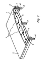
- FIG. 1 shows templates 2 lying on a foam mat 1, which are covered by a glass plate 3.
- the glass plate is supported on a frame 4.
- the underside of the plate represents the image plane.
- the frame 4 encloses a trough 5 and has a circumferential seal 8 on which the plate 3 rests.
- Plate 3, frame 4 and trough 5 form a vacuum-tight space which is evacuated during the operation of the device.
- the frame 4 has vacuum openings 41 which pass the vacuum to the glass plate 3 and the top of the air cushion via channels 42 which pass through the frame. When the vacuum is created, air is simultaneously sucked into the air cushion 6, which is connected to the external pressure via the opening 7.
- the air cushion 6 expands evenly on all sides and thus presses the templates 2 against the underside of the glass plate.
- the glass plate is pressed against the frame 4 by the vacuum and thus pulled down into the focus plane. It prevails on the glass plate Pressure equalization, and it is ensured by the vacuum and the air cushion that the original lies within the sharpness level 9.
- an additional measure namely by a slight overpressure at the air cushion opening 7, achieves that the bending of the glass plate that occurs due to the weight of the glass plate, is lifted, and the lower edge of the plate lies exactly in the focal plane everywhere.
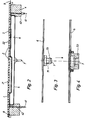
- Figure 2 shows a cross section through the jig shown in Figure 1. It should be noted that a plurality of vacuum channels 42 can be provided distributed over the entire frame, so that a uniform vacuum is created between the glass plate and the air cushion. From Figure 2 it can be seen that templates of different thicknesses, e.g. B. the template 21 and the template 22, regardless of their thickness can be pressed flat against the glass plate. The same also applies to adhesive assembly or overlapping template parts.
- Figure 3 shows the air cushion 6 in section with its air inlet opening 7, which is designed as a screwed connector 71, which is screwed to the air cushion in the manner of a bicycle air valve.
- Figure 4 shows a receptacle 72 for the nozzle 71, which is screwed to the bottom of the tub 5. The spigot of FIG. 3 engages in this receptacle, as shown in broken lines in FIG. 4, and is sealed with an O-ring 73.
- the advantages of the present invention lie essentially in the fact that uneven or laminated templates are pressed flat against the underside of the glass plate. At The original is therefore always in the focus area of the scanning optics, and during recording the recording material is always in the focus range of the light beam to be recorded.
- the absolute level of the vacuum is not critical to the operation of the invention, but it is necessary that a minimum vacuum be present so that the originals are pressed into the plane of the originals. Another advantage is that there is no risk of breakage for the glass plate even at a very high vacuum, since there is pressure equalization between the glass plate and the airbag. Better scanning quality can also be achieved by reducing the thickness of the glass plate, because the thinner glass plates can be used due to the pressure compensation and the compensation of the deflection of the glass plate.
Landscapes
- Physics & Mathematics (AREA)
- Engineering & Computer Science (AREA)
- Multimedia (AREA)
- Signal Processing (AREA)
- Fluid Mechanics (AREA)
- General Physics & Mathematics (AREA)
- Holders For Sensitive Materials And Originals (AREA)
- Facsimile Scanning Arrangements (AREA)
- Exposure Or Original Feeding In Electrophotography (AREA)
- Exposure And Positioning Against Photoresist Photosensitive Materials (AREA)
- Facsimiles In General (AREA)
Priority Applications (1)
| Application Number | Priority Date | Filing Date | Title |
|---|---|---|---|
| AU42220/85A AU4222085A (en) | 1984-05-12 | 1985-05-09 | Vacuum and air pressure assisted flat sheet support device |
Applications Claiming Priority (2)
| Application Number | Priority Date | Filing Date | Title |
|---|---|---|---|
| DE3417691 | 1984-05-12 | ||
| DE19843417691 DE3417691A1 (de) | 1984-05-12 | 1984-05-12 | Vorrichtung zur aufspannung von abtast- und aufzeichnungsvorlagen in der reproduktionstechnik |
Publications (2)
| Publication Number | Publication Date |
|---|---|
| EP0168529A2 true EP0168529A2 (fr) | 1986-01-22 |
| EP0168529A3 EP0168529A3 (fr) | 1986-08-13 |
Family
ID=6235683
Family Applications (1)
| Application Number | Title | Priority Date | Filing Date |
|---|---|---|---|
| EP84115681A Withdrawn EP0168529A3 (fr) | 1984-05-12 | 1984-12-18 | Support pour les originaux et matériaux sensibles dans la technique de reproduction |
Country Status (3)
| Country | Link |
|---|---|
| EP (1) | EP0168529A3 (fr) |
| JP (1) | JPS60251756A (fr) |
| DE (1) | DE3417691A1 (fr) |
Families Citing this family (1)
| Publication number | Priority date | Publication date | Assignee | Title |
|---|---|---|---|---|
| JP2779817B2 (ja) * | 1988-12-15 | 1998-07-23 | リギオ 脇 | 感光材料等の吸着保持装置 |
Family Cites Families (8)
| Publication number | Priority date | Publication date | Assignee | Title |
|---|---|---|---|---|
| DE7517890U (de) * | 1975-10-16 | Boeger Duplomat Apparate Kg | Vakuumanpreßvorrichtung für Kontaktkopierrahmen | |
| US1209419A (en) * | 1915-09-15 | 1916-12-19 | Harry D Farquhar | Photographic device. |
| DE726567C (de) * | 1941-04-23 | 1942-10-16 | Wilhelm Tackenberg | Zweiteilige Filmfuehrung fuer Vergroesserungsgeraete |
| US3455634A (en) * | 1966-04-18 | 1969-07-15 | Bariquand & Marre Atel | Pneumatic printers for photomechanical processes |
| GB1222299A (en) * | 1969-10-20 | 1971-02-10 | Charles Game | An improved apparatus for use in the reproduction of sheet originals |
| GB1511332A (en) * | 1974-04-30 | 1978-05-17 | Hoechst Ag | Printing frame |
| JPS57190539U (fr) * | 1981-05-26 | 1982-12-03 | ||
| US4486786A (en) * | 1981-09-08 | 1984-12-04 | Canon Kabushiki Kaisha | Original reading device |
-
1984
- 1984-05-12 DE DE19843417691 patent/DE3417691A1/de not_active Withdrawn
- 1984-12-18 EP EP84115681A patent/EP0168529A3/fr not_active Withdrawn
-
1985
- 1985-05-13 JP JP9974885A patent/JPS60251756A/ja active Granted
Also Published As
| Publication number | Publication date |
|---|---|
| EP0168529A3 (fr) | 1986-08-13 |
| JPH037315B2 (fr) | 1991-02-01 |
| JPS60251756A (ja) | 1985-12-12 |
| DE3417691A1 (de) | 1985-11-28 |
Similar Documents
| Publication | Publication Date | Title |
|---|---|---|
| DE69322778T2 (de) | Vakuumplatte | |
| DE68915463T2 (de) | Anordnung zum Zusammenspannen eines Stapels von Brennstoffzellenelementen. | |
| DE3034973C2 (de) | Vorrichtung zum Einziehen eines Polsterstoffes in eine Hinterschäumform | |
| DE2033444C3 (de) | Vorrichtung zum Eindiffundieren von Dotierstoffen in Scheiben aus Halbleitermaterial | |
| EP0168529A2 (fr) | Support pour les originaux et matériaux sensibles dans la technique de reproduction | |
| US3455634A (en) | Pneumatic printers for photomechanical processes | |
| DE8437024U1 (de) | Vorrichtung zur aufspannung von abtast- und aufzeichnungsvorlagen in der reproduktionstechnik | |
| DE69320878T2 (de) | Maske für eine Belichtungstrommel | |
| DE4305475C1 (de) | Streustrahlenraster eines Röntgendiagnostikgerätes | |
| DE2927374A1 (de) | Filmhalter fuer reprokameras o.dgl. | |
| DE69806081T2 (de) | Schablonendruckvorrichtung | |
| US1547871A (en) | Apparatus for the production of artistic prints and impressions | |
| DE102022206904A1 (de) | Befestigungsverfahren und befestigungsvorrichtung | |
| DE69120015T2 (de) | Kontaktkopiervorrichtung zur Bildherstellung einer transparenten Vorlage auf photographischem Film | |
| US4241993A (en) | Mount for originals in photographic devices | |
| DE2511726C3 (de) | Hydraulische Presse mit einer Druckzelle mit elastischer Membran und Formkissen | |
| DE10011940C2 (de) | Vorrichtung zur Prüfung von Filterkassetten | |
| DE7922341U1 (de) | Vakuum-aufspanntisch zum aufspannen von duennen folien | |
| US4620787A (en) | Stencil screen exposure apparatus | |
| DE3928419A1 (de) | Auflageplatte fuer eine vorlage | |
| DE4119469C2 (de) | Vorrichtung zur Herstellung von Druckplatten | |
| DE2230111A1 (de) | Kopierrahmen mit transparentplatte zur aufnahme von lichtempfindlichem traegermaterial | |
| DE3222183C1 (de) | Vorrichtung zum bleibenden Beschichten großformatiger Platten | |
| US1857381A (en) | Negative holder for photographic printing machines | |
| DE4119470C2 (de) | Vorrichtung zur Herstellung von Druckplatten |
Legal Events
| Date | Code | Title | Description |
|---|---|---|---|
| PUAI | Public reference made under article 153(3) epc to a published international application that has entered the european phase |
Free format text: ORIGINAL CODE: 0009012 |
|
| AK | Designated contracting states |
Designated state(s): AT BE CH DE FR GB IT LI NL SE |
|
| PUAL | Search report despatched |
Free format text: ORIGINAL CODE: 0009013 |
|
| AK | Designated contracting states |
Kind code of ref document: A3 Designated state(s): AT BE CH DE FR GB IT LI NL SE |
|
| STAA | Information on the status of an ep patent application or granted ep patent |
Free format text: STATUS: THE APPLICATION IS DEEMED TO BE WITHDRAWN |
|
| 18D | Application deemed to be withdrawn |
Effective date: 19870214 |
|
| RIN1 | Information on inventor provided before grant (corrected) |
Inventor name: PENZA, HANS Inventor name: KNOLL, HARTMUT |