EP0168577A1 - Vorrichtung zur Herstellung fotografischer Aufnahmen von Bildschirmbildern - Google Patents
Vorrichtung zur Herstellung fotografischer Aufnahmen von Bildschirmbildern Download PDFInfo
- Publication number
- EP0168577A1 EP0168577A1 EP85105757A EP85105757A EP0168577A1 EP 0168577 A1 EP0168577 A1 EP 0168577A1 EP 85105757 A EP85105757 A EP 85105757A EP 85105757 A EP85105757 A EP 85105757A EP 0168577 A1 EP0168577 A1 EP 0168577A1
- Authority
- EP
- European Patent Office
- Prior art keywords
- film
- screen
- film stage
- stage
- recordings
- Prior art date
- Legal status (The legal status is an assumption and is not a legal conclusion. Google has not performed a legal analysis and makes no representation as to the accuracy of the status listed.)
- Granted
Links
- 238000006073 displacement reaction Methods 0.000 claims abstract description 11
- 238000002604 ultrasonography Methods 0.000 claims abstract description 4
- 238000003384 imaging method Methods 0.000 claims abstract description 3
- 238000004140 cleaning Methods 0.000 claims description 2
- 238000004519 manufacturing process Methods 0.000 description 3
- 238000010276 construction Methods 0.000 description 1
- 238000003745 diagnosis Methods 0.000 description 1
- 230000005484 gravity Effects 0.000 description 1
- 230000037431 insertion Effects 0.000 description 1
- 238000003780 insertion Methods 0.000 description 1
Images


Classifications
-
- G—PHYSICS
- G03—PHOTOGRAPHY; CINEMATOGRAPHY; ANALOGOUS TECHNIQUES USING WAVES OTHER THAN OPTICAL WAVES; ELECTROGRAPHY; HOLOGRAPHY
- G03B—APPARATUS OR ARRANGEMENTS FOR TAKING PHOTOGRAPHS OR FOR PROJECTING OR VIEWING THEM; APPARATUS OR ARRANGEMENTS EMPLOYING ANALOGOUS TECHNIQUES USING WAVES OTHER THAN OPTICAL WAVES; ACCESSORIES THEREFOR
- G03B15/00—Special procedures for taking photographs; Apparatus therefor
- G03B15/003—Apparatus for photographing CRT-screens
Definitions
- the invention relates to a device for producing photographic recordings of X-ray or ultrasound or the like images appearing on a screen of a monitor, an objective being adjustable between the screen and a film stage holding the film in the exposure position for sharp imaging of the screen image on the film is.
- a device of this type for producing cinematographic recordings of screen images is known for example from DE-OS 31 46 963.
- cinematographic recordings are not suitable for a number of diagnostic purposes.
- An X-ray recording device with which several recordings can be recorded next to and below one another on a sheet of film, is known from DE-AS 24 09 154.
- X-ray recording devices are known which are connected to loading and unloading and / or developing stations for the sheet films to be used, for example by DE-OS 31 25 397 or DE-PS 22 40 507.
- these are not Devices suitable for screen photography, which are becoming increasingly important, for example in X-ray and ultrasound diagnosis.
- the invention has for its object to provide a device of the type mentioned in such a way that recordings of screen images in a simple manner in terms of device and operation can be taken in a different arrangement and size on a sheet of film next to and with one another.
- the sheet film stage can be moved in a coordinate direction for the production of columns of recordings and for loading and unloading with film
- the monitor in the two perpendicular coordinate directions for adjusting the image size on the one hand and for the production of image rows on the other hand can be displaced transversely to the image columns
- a simple adjustment mechanism is sufficient for setting the film stage and monitor, which can be operated and adjusted if necessary with simple hand movements. Due to the simple adjustability, it is also possible to use a Relatively simple control electronics with program selection to select and trigger the size and arrangement of the desired photographic recordings on a sheet of film using a dialing keyboard. This arrangement also has other advantages.
- the displacement of the monitor can be used to adjust the image size and also to change the deflecting mirror in a certain position or a sequence of certain positions in such a way that instead of sheet film recordings, still or motion picture recordings can be made on roll film either with a roll film camera can be, for example, if this is desired for special diagnostic or archiving purposes.
- FIGs 1 and 2 a schematically illustrated device housing with 1, its photographic receiving part with 1a and its film loading and unloading part with 1b and a passage slot between the receiving part 1a and the film loading and unloading part 1b with 1c.
- the passage slot 1c extends in the direction of a coordinate, according to the figures in the direction of the X coordinate, corresponding to the width of a film stage 2 and has a width in the direction Y perpendicular to this and to the direction of displacement Z of the film stage 2, which is sufficient that the upper edge 2a of the film stage 2 facing it can be pushed into the area of the pair of transport rollers 3a, 3b from the receiving part 1a into the loading and unloading part 1b.
- the film stage 2 has a known suction device 4 and known suction holes, not shown, through which a film sheet applied to the receiving side of the film stage 2 can be securely held in the vertical position predetermined by the vertical position of the film stage 2.
- the top edge of the film stage 2 as is most clearly visible in FIG. 4, has cutouts 2b at certain intervals, while the transport rollers 3a, 3b, which are already in the loading and unloading part 1b, into several roller pair pieces 3a, 3b of slightly less than that The width of the cutouts 2b are divided and lie at the points in the direction X where the cutouts 2b also lie.
- the film stage 2 is in a vertical direction to be described in more detail later tion, namely in the Z direction, up and down, with the lower part of the roller pair pieces 3a, 3b engaging in their uppermost loading and unloading position in their cutouts 2b.
- inserts 5 and 6 or still further inserts of which at least one insert 5 is a sheet film storage magazine with transport means for transporting a film to the roller pair pieces 3a, 3b contains.
- the second insert 6 can be an intermediate magazine for the light-tight insertion of exposed film also by means of the roller pair pieces 3a, 3b.
- a developing machine can also be provided directly as a further part following the loading and unloading part 1b. In a known manner, all of these storage magazines or intermediate magazines and possibly the developing machine are designed to be light-tight in their functional position.
- FIGS. 1 and 2 only the further transport roller pairs provided before and after the roller pair pieces 3a, 3b are indicated schematically in FIGS. 1 and 2.
- the film stage 2 is moved to its uppermost position, shown in FIG. 4 or indicated by dash-dotted lines in FIG. 1, the film to be unloaded, which is accessible in the cutouts 2h, being switched off by the roller pair pieces with the suction device switched off 3a, 3b detected and fed to the intermediate magazine 6 or the developing machine becomes.
- new film to be introduced is removed from the storage magazine and fed back to the film stage 2 via the roller pair pieces 3a, 3b. If it is in its correct position there, the suction device comes into operation again and the film stage 2 is lowered into its working position.
- a plurality of arms 2c with exact bores are provided on the back of the stage, which are vertically displaceable on at least two parallel rods, of which only one rod 7 is visible.
- a toothed belt drive 8 or cable is driven via two rollers 9, 10 by means of an electric motor 11 from a control circuit 12 by certain distances and connected at a point 8a to the film stage 2, so that when the toothed belt or cable 8 is moved, the film stage 2 by corresponding Pieces up or down in the direction Z is taken.
- the film stage 2 in the Z direction six identical steps per column, for example first upwards for the first recording column and then down again for the second recording column and again upwards for the third recording column and downwards again for the fourth column.
- the steps of the film stage 2 in the Z direction are programmed accordingly differently.
- the stage 2 only performs an upward or downward movement in the Z direction.
- a monitor 14 the screen 14a of which is to be photographed, is in the two for the direction of displacement Z of the film stage 2 vertical directions X and Y slidably mounted.
- the screen 14a could be parallel to the film stage 2 and between them a shooting lens 15 could be arranged. According to the exemplary embodiment shown, however, the screen 14a to be photographed lies horizontally upward in the XY plane.
- the monitor 14 can be displaced on parallel support rods 16 of a frame 17, which run in the Y direction, with bores (not shown in more detail), specifically by means of a spindle 19 driven by a second electric motor 18.
- the objective 15 is also on the guide rods 16 by means of a further spindle 20 slidably guided.
- the further spindle 20 can be driven by a third electric motor 21.
- the control of the position of lens 15 and screen 14a in the Y direction corresponding to a selected or programmed enlargement or reduction of a screen recording is again carried out via the control circuit 12 in accordance with that in the dialing keyboard 13 chose program.
- the guide rods 16 with the supports 17 and 22 for the monitor 14 and lens 15 are held on a main support plate 23 which is parallel to the film stage 2 and has an exposure window or an image field diaphragm 23a and which in turn is attached to guide rods 24 in which run in the X direction and are fastened in the housing 1
- the X-direction is slidably mounted and can be shifted step by step from picture to picture of each picture line by a third spindle 25 by means of a fourth electric motor 26.
- This fourth electric motor 26 is also controlled by the control circuit 12 in accordance with a planned program.
- the setting of an enlargement or reduction of the screen images to be photographed is thus carried out by correspondingly moving the lens 15 and the screen 14a in the Y direction, the recording of the images in a vertical column by moving the film stage 2 in the Z direction with the screen 14a stationary and the recording the images in a horizontal column by moving the screen 14a together with the lens 15 in the X direction with the film stage 2 at a standstill.
- a deflection mirror 27 which is inclined by 45 ° relative to both must be slidably mounted together with the screen 14a between the screen 14a and the lens 15.
- this mirror 27 In order to be able to clean this mirror 27 on the one hand and on the other hand to be able to pivot it into a further position in which, according to FIG. 2, it is in a position rotated by 90 ° to the image that of the screen image through the lens 28a of a roll film chamber 28 on its film plane, the deflection mirror 27 is mounted in the monitor support frame 17 so as to be pivotable about an axis 29.
- a control pin 30 which extends in the X direction and which engages in a slot curve 31 fixed to the device is arranged on at least one angle of the mirror 7 lying in a YZ plane.
- the slot curve 31 is designed as a circular arc around the axis of rotation 29, so that the mirror 27 is counterclockwise from the position shown in FIG , lockable cover of the housing can be swiveled upwards for cleaning purposes by hand.
- the slit curve 31 has a small curve piece 31b which is shaped such that the mirror 27, when the monitor 14 is moved further beyond its end position for plane film recordings, into the position shown in FIG. 2, inclined 90 ° counterclockwise upwards Position is pivoted up to a stop 32. In this position shown in Figure 2, the screen image of the monitor 14 is then thrown into the lens 28a of the roll film camera 28. This is also accessible through the or another housing cover and can be operated in this way or by means of a remote control device. It is releasably attached in any known manner in the device 1 or in the receiving space la.
- light-tight bellows 33 are provided between the flat film stage 2, the lens 15 and the support frame 17 for the monitor.
- the monitor arrangement may be slightly easier; on the other hand, in this case the swiveling in of a deflection mirror for roll film recordings becomes considerably more difficult since either no bellows are provided or these have to be temporarily decoupled and pushed together to swivel in one or more deflection mirrors.
- the camera 28 is still to be easily accessible, two deflecting mirrors inclined to one another should be able to be pivoted in for the production of roll film recordings.
- a cinema camera could of course also be used if necessary.
- the belt drive 8 shown or the spindle drives 19, 20, 25, depending on the expediency other drives known in lens construction, such as worm gears or gear and rack and pinion drives, could also take place.
Landscapes
- Physics & Mathematics (AREA)
- General Physics & Mathematics (AREA)
- Projection-Type Copiers In General (AREA)
- Cameras In General (AREA)
Abstract
Description
- Die Erfindung betrifft eine Vorrichtung zur Herstellung fotografischer Aufnahmen von auf einem Bildschirm eines Monitors erscheinenden Röntgen- oder Ultraschall- oder dergl. Bildern, wobei ein Objektiv zwischen dem Bildschirm und einer den Film in Belichtungsstellung haltenden Filmbühne zur scharfen Abbildung des Bildschirmbildes auf dem Film einstellbar angeordnet ist.
- Eine Vorrichtung dieser Art zur Herstellung kinematografischer Aufnahmen von Bildschirmbildern ist beispielsweise durch die DE-OS 31 46 963 bekannt. Kinematografische Aufnahmen sind jedoch für eine Reihe diagnostischer Zwecke nicht geeignet. Ein Röntgenaufnahmegerät, mit welchem auf einem Blattfilm mehrere Aufnahmen neben- und untereinander aufgenommen werden können, ist durch die DE-AS 24 09 154 bekannt geworden. Darüber hinaus sind Röntgenaufnahmegeräte bekannt, die mit Be- und Entlade- und/oder Entwicklungsstationen für die zu verwendenden Blattfilme verbunden sind, z.B. durch die DE-OS 31 25 397 oder die DE-PS 22 40 507. Hierbei handelt es sich aber nicht um für die Bildschirmfotografie geeignete Vorrichtungen, die z.B. in der Röntgen- und Ultraschalldiagnose eine immer größere Bedeutung gewinnen.
- Der Erfindung liegt die Aufgabe zugrunde, eine Vorrichtung der eingangs genannten Art so auszubilden, daß Aufnahmen von Bildschirmbildern auf vorrichtungsmäßig und bedienungsmäßig einfache Weise in verschiedener Anordnung und Größe auf einem Blattfilm neben- und untereinander aufgenommen werden können.
- Diese Aufgabe wird erfindungsgemäß gelöst durch die Merkmale des Hauptanspruchs. Weitere vorteilhafte Merkmale der Erfindung sind den Unteransprüchen entnehmbar.
- Dadurch, daß die Blattfilmbühne in einer Koordinatenrichtung zur Herstellung von Spalten von Aufnahmen und zur Be- und Entladung mit Film verschiebbar ist, während der Monitor in den beiden hierzu senkrechten Koordinatenrichtungen zur Einstellung der Bildgröße einerseits und zur Herstellung von Bilderreihen quer zu den Bildspalten andererseits verschiebbar ist, reicht eine einfache Verstellmechanik für die Einstellung von Filmbühne und Monitor aus, die ggf. durch einfache Handgriffe bedien- und einstellbar ist. Durch die einfache Einstellbarkeit ist es aber auch möglich, mittels einer relativ einfachen Steuerelektronik mit Programmvorwahl die Größe und Anordnung der gewünschten fotografischen Aufnahmen auf einem Blattfilm mittels einer Wähltastatur vorzuwählen und auszulösen. Diese Anordnung bringt aber auch noch weitere Vorteile. So kann bei Verwendung eines schwenkbaren Umlenkspiegels die Verschiebung des Monitors zur Bildgrößeneinstellung und auch noch dazu verwendet werden, in einer bestimmten Stellung oder einer Folge von bestimmten Stellungen den Umlenkspiegel so umzusteuern, daß anstelle von Planfilmaufnahmen wahlweise mit einer Rollfilmkamera Steh- oder Laufbildaufnahmen auf Rollfilm gemacht werden können, wenn dies z.B. für besondere diagnostische oder Archivierungszwecke erwünscht ist.
- Die Erfindung wird anhand von Zeichnungen näher erläutert. Es zeigen
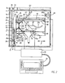
- Fig. 1 eine halbschematische Darstellung einer erfindungsgemäßen Vorrichtung für die Bildschirmfotografie in einer der Stellungen für Planfilmaufnahmen,
- Fig. 2 eine abgebrochene Darstellung der Vorrichtung nach Figur 1 in der Stellung für fotografische Aufnahmen mittels einer Rollfilmkamera,
- Fig. 3a bis 3h mögliche Formatkombinationen bei Reihenbildschirmaufnahmen auf jeweils einen Planfilm mittels der Vorrichtung nach Figur 1,
- Fig. 4 einen die Transportrollen für die Be- und Entladung der Planfilmbühne darstellenden Ausschnitt der Vorrichtung nach Figur 1.
- In den Figuren 1 und 2 sind ein schematisch dargestelltes Gerätegehäuse mit 1, dessen fotografischer Aufnahmeteil mit 1a und dessen Filmbe- und -entladeteil mit 1b und ein Durchtrittsschlitz zwischen dem Aufnahmeteil 1a und dem Filmbe- und -entladeteil 1b mit 1c bezeichnet. Der Durchtrittsschlitz 1c erstreckt sich in Richtung einer Koordinate, gemäß den Figuren in Richtung der X-Koordinate, entsprechend der Breite einer Filmbühne 2 und weist in der hierzu und zur Verschieberichtung Z der Filmbühne 2 senkrechten Richtung Y eine Breite auf, die ausreichend ist, daß die ihm zugewandte Oberkante 2a der Filmbühne 2 bis in den Bereich des Transportwalzenpaares 3a, 3b vom Aufnahmeteil 1a in den Be- und Entladeteil 1b hineingeschoben werden kann. Die Filmbühne 2 weist eine bekannte Ansaugeinrichtung 4 und nicht gezeigte, bekannte Ansauglöcher auf, durch die ein auf die Aufnahmeseite der Filmbühne 2 aufgebrachtes Filmblatt in der durch die vertikale Lage der Filmbühne 2 vorgegebenen vertikalen Stellung sicher gehalten werden kann. Die Oberkante der Filmbühne 2 weist, wie in Figur 4 am deutlichsten sichtbar ist, in bestimmten Abständen Ausschnitte 2b auf, während die Transportwalzen 3a, 3b die bereits im Be- und Entladeteil lb liegen, in mehrere Walzenpaarstücke 3a, 3b von etwas weniger als der Breite der Ausschnitte 2b aufgeteilt sind und an den Stellen in Richtung X liegen, an denen auch die Ausschnitte 2b liegen. Die Filmbühne 2 ist in später genauer zu beschreibender Weise in vertikaler Richtung, nämlich in Z-Richtung, auf- und abwärts verschiebbar, wobei in ihrer obersten Be- und Entladestellung in ihre Ausschnitte 2b der untere Teil der Walzenpaarstücke 3a, 3b eingreift.
- Im Be- und Entladeteil lb sind in an sich bei Röntgenaufnahmegeräten oder Kassettenbe- und -entladegeräten bekannter Weise Einschübe 5 und 6 oder noch weitere Einschübe vorhanden, von denen mindestens der eine Einschub 5 ein Blattfilmvorratsmagazin mit Transportmitteln zum Transportieren eines Films zu den Walzenpaarstücken 3a, 3b enthält. Der zweite Einschub 6 kann ein Zwischenmagazin darstellen zum lichtdichten Einführen von belichtetem Film ebenfalls mittels der Walzenpaarstücke 3a, 3b. Genausogut kann aber auch als weiterer Teil im Anschluß an den Be- und Entladeteil 1b direkt eine Entwicklungsmaschine vorgesehen sein. In bekannter Weise sind alle diese Vorrats- oder Zwischenmagazine und ggf. die Entwicklungsmaschine einerseits in ihrer Funktionsstellung lichtdicht ausgeführt. Da dies aber an sich bekannt und auf jede bekannte Weise ausführbar und für die vorliegende Erfindung nicht wesentlich ist, sind ohne Bezugsziffern in den Figuren 1 und 2 nur noch die vor bzw. nach den Walzenpaarstücken 3a, 3b vorgesehenen weiteren Transportwalzenpaare schematisch angedeutet. Zum Be- bzw. Entladen wird die Filmbühne 2 bis in ihre oberste, in Figur 4 gezeigte bzw. in Figur 1 strichpunktiert angedeutete Stellung bewegt, wobei dann zu entladender Film, der in den Ausschnitten 2h zugänglich liegt, unter Abschaltung der Ansaugvorrichtung durch die Walzenpaarstücke 3a, 3b erfaßt und dem Zwischenmagazin 6 bzw. der Entwicklungsmaschine zugeführt wird. Umgekehrt wird neu einzuführender Film dem Vorratsmagazin entnommen und wieder über die Walzenpaarstücke 3a, 3b der Filmbühne 2 zugeführt. Wenn er dort seine richtige Lage einnimmt, tritt die Ansaugvorrichtung wieder in Funktion, und die Filmbühne 2 wird in ihre Arbeitsstellung heruntergefahren.
- Für die Lagerung der Filmbühne 2 ist jede für eine bekannte, exakte Parallelverschiebung in einer Richtung geeignete, schritt- oder abschnittweise antreibbare mechanische oder mechanisch-elektrische Verschiebevorrichtung verwendbar. Beim gezeigten Ausführungsbeispiel sind an der Bühnenrückseite mehrere Arme 2c mit exakten Bohrungen vorgesehen, die an wenigstens zwei parallelen Stangen, von denen nur eine Stange 7 sichtbar ist, vertikal verschiebbar sind. Ein Zahnriemenantrieb 8 oder Seilzug ist über zwei Rollen 9, 10 mittels eines Elektromotors 11 von einer Steuerschaltung 12 aus um bestimmte Wegstrecken antreibbar und an einer Stelle 8a mit der Filmbühne 2 verbunden, so daß bei Bewegung des Zahnriemens oder Seilzugs 8 die Filmbühne 2 um entsprechende Stücke aufwärts bzw. abwärts in Richtung Z mitgenommen wird. Die entsprechenden Wegstrecken richten sich nach der an einer Wähltastatur 13 vorgewählten Funktion, wobei beispielsweise bei einer Einteilung und Größe der aufzunehmenden Bilder gemäß Figur 3a die Filmbühne 2 in Z-Richtung je Spalte sechs gleiche Schritte, z.B. zuerst nach aufwärts für die erste Aufnahmenspalte und dann wieder nach abwärts für die zweite Aufnahmenspalte und wieder nach aufwärts für die dritte Aufnahmenspalte und wieder nach abwärts für die vierte Aufnahmenspalte ausführt. Bei entsprechend anders aufgeteilten, vorwählbaren Aufnahmefeldeinteilungen, z.B. nach den Figuren 3b bis 3h sind die Schritte der Filmbühne 2 in Z-Richtung entsprechend anders programmiert. Die Bühne 2 führt dabei nur eine Auf- oder Abwärtsbewegung in Z-Richtung durch.
- Um nun Aufnahmen auf dem Film nicht nur in vertikalen Spalten, sondern auch in horizontalen Reihen, also in X-Richtung nebeneinander und außerdem in verschiedenen Größen aufnehmen zu können, ist ein Monitor 14, dessen Bildschirm 14a abfotografiert werden soll, in den beiden zur Verschieberichtung Z der Filmbühne 2 senkrechten Richtungen X und Y verschiebbar gelagert. Der Bildschirm 14a könnte dabei parallel zur Filmbühne 2 und zwischen beiden könnte einstellbar ein Aufnahmeobjektiv 15 angeordnet sein. Gemäß dem gezeigten Ausführungsbeispiel liegt jedoch der abzufotografierende Bildschirm 14a horizontal nach oben gerichtet in der X-Y-Ebene. Der Monitor 14 ist dabei an in Y-Richtung verlaufenden parallelen Trägerstangen 16 eines Rahmens 17 mit nicht näher gezeigten Bohrungen verschiebbar, und zwar mittels einer über einen zweiten Elektromotor 18 angetriebenen Spindel 19. An den Führungsstangen 16 ist auch das Objektiv 15 mittels einer weiteren Spindel 20 verschiebbar geführt. Die weitere Spindel 20 ist durch einen dritten Elektromotor 21 antreibbar. Die Steuerung der einer gewählten oder programmierten Vergrößerung bzw. Verkleinerung einer Bildschirmaufnahme entsprechenden Lage von Objektiv 15 und Bildschirm 14a in Y-Richtung erfolgt wiederum über die Steuerschaltung 12 entsprechend dem in der Wähltastatur 13 ausgewählten Programm. Die Führungsstangen 16 mit den Trägern 17 und 22 für Monitor 14 und Objektiv 15 sind an einer zur Filmbühne 2 parallelen, ein Belichtungsfenster oder eine Bildfeldblende 23a aufweisenden Hauptträgerplatte 23 gehalten, die ihrerseits an in X-Richtung verlaufenden, im Gehäuse 1 befestigten Führungsstangen 24 in X-Richtung verschiebbar gelagert und durch eine dritte Spindel 25 mittels eines vierten Elektromotors 26 schrittweise von Bild zu Bild jeder Bildzeile verschiebbar ist. Auch dieser vierte Elektromotor 26 wird durch die Steuerschaltung 12 entsprechend einem geplanten Programm gesteuert.
- Die Einstellung einer Vergrößerung bzw. Verkleinerung der abzufotografierenden Bildschirmbilder erfolgt also durch entsprechende Verschiebung von Objektiv 15 und Bildschirm 14a in Y-Richtung, das Aufnehmen der Bilder in einer vertikalen Spalte durch Verschieben der Filmbühne 2 in Z-Richtung bei stillstehendem Bildschirm 14a und das Aufnehmen der Bilder in einer horizontalen Spalte durch Verschieben des Bildschirms 14a zusammen mit dem Objektiv 15 in X-Richtung bei stillstehender Filmbühne 2.
- Nachdem gemäß dem gezeigten Ausführungsbeispiel der Bildschirm 14a horizontal liegt, muß zwischen Bildschirm 14a und Objektiv 15 ein gegenüber beiden um 45° geneigter Umlenkspiegel 27 zusammen mit dem Bildschirm 14a verschiebbar gelagert sein. Um diesen Spiegel 27 einerseits reinigen zu können und andererseits in eine weitere Stellung schwenken zu können, in der er gemäß Fig. 2 eine um 90° gedrehte Stellung zum Abbilden des Bildschirmbildes durch das Objektiv 28a einer Rollfilmkammera 28 auf deren Filmebene einnimmt, ist der Umlenkspiegel 27 in dem Monitorträgerrahmen 17 um eine Achse 29 schwenkbar gelagert. Die zur Achse 29 parallele, dieser entfernter liegende Kante des Spiegels 27 liegt unter der Wirkung der Schwerkraft in der normalen Stellung für Planfilmaufnahmen auf dem Rand des Monitors 14 oder einem Anschlag auf. An wenigstens einem in einer Y-Z-Ebene liegenden Winkel des Spiegels ?7 ist ein in X-Richtung verlaufender Steuerstift 30 angeordnet, der in eine gerätefeste Schlitzkurve 31 eingreift. In ihrem einen Endbereich 31a, in dem der Spiegel 27 am weitesten von der Filmbühne 2 entfernt ist, ist die Schlitzkurve 31 als Kreisbogen um die Drehachse 29 ausgebildet, so daß der Spiegel 27 aus der Stellung nach Fig. 1 entgegen dem Uhrzeigersinn durch einen angedeuteten, verschließbaren Deckel des Gehäuses nach oben zu Reinigungszwecken von Hand schwenkbar ist. An ihrem filmbühnennahen Ende weist die Schlitzkurve 31 ein kleines Kurvenstück 31b auf, das so geformt ist, daß der Spiegel 27 beim Weiterbewegen des Monitors 14 über dessen Endstellung für Planfilmaufnahmen hinaus in die in Figur 2 gezeigte, um 90° entgegen dem Uhrzeigersinn nach oben geneigte Stellung bis zu einem Anschlag 32 hochgeschwenkt wird. In dieser in Figur 2 gezeigten Stellung wird das Bildschirmbild des Monitors 14 dann in das Objektiv 28a der Rollfilmkamera 28 geworfen. Diese ist ebenfalls durch den oder einen weiteren Gehäusedeckel zugänglich und auf diese Weise oder mittels einer Fernbedienungsvorrichtung bedienbar. Sie ist auf irgend eine bekannte Weise im Gerät 1 bzw. im Aufnahmeraum la lösbar befestigt.
- Es bedarf wohl kaum einer Erwähnung, daß zwischen Planfilmbühne 2, Objektiv 15 und dem Trägerrahmen 17 für den Monitor lichtdichte Balgen 33 vorgesehen sind. Ist der Bildschirm 14a parallel zur Filmbühne 2 angeordnet, so ist zwar die Monitoranordnung u.U. geringfügig einfacher; dagegen wird in diesem Fall das Einschwenken eines Umlenkspiegels für Rollfilmaufnahmen erheblich schwieriger, da dann entweder keine Balgen vorgesehen werden oder diese zum Einschwenken eines oder mehrerer Umlenkspiegel vorübergehend abgekoppelt und zusammengeschoben werden müssen. Soll dabei die Kamera 28 noch gut zugänglich sein, so müßten zwei zueinander geneigte Umlenkspiegel für die Herstellung von Rollfilmaufnahmen einschwenkbar sein. An die Stelle einer Rollfilmstehbildkamera könnte bei Bedarf naturgemäß auch eine Kinokamera treten. An die Stelle des gezeigten Riementriebs 8 bzw. der Spindeltriebe 19, 20, 25 könnten je nach Zweckmäßigkeit auch andere im Objektivbau bekannte Antriebe, wie Schneckengänge oder Zahnrad- und Zahnstangentriebe, treten.
Claims (8)
Applications Claiming Priority (2)
| Application Number | Priority Date | Filing Date | Title |
|---|---|---|---|
| DE3418960 | 1984-05-22 | ||
| DE19843418960 DE3418960A1 (de) | 1984-05-22 | 1984-05-22 | Vorrichtung zur herstellung fotografischer aufnahmen von bildschirmbildern |
Publications (2)
| Publication Number | Publication Date |
|---|---|
| EP0168577A1 true EP0168577A1 (de) | 1986-01-22 |
| EP0168577B1 EP0168577B1 (de) | 1988-03-09 |
Family
ID=6236494
Family Applications (1)
| Application Number | Title | Priority Date | Filing Date |
|---|---|---|---|
| EP85105757A Expired EP0168577B1 (de) | 1984-05-22 | 1985-05-10 | Vorrichtung zur Herstellung fotografischer Aufnahmen von Bildschirmbildern |
Country Status (4)
| Country | Link |
|---|---|
| US (1) | US4615596A (de) |
| EP (1) | EP0168577B1 (de) |
| JP (1) | JPH0652368B2 (de) |
| DE (1) | DE3418960A1 (de) |
Cited By (2)
| Publication number | Priority date | Publication date | Assignee | Title |
|---|---|---|---|---|
| EP0176092B1 (de) * | 1984-09-26 | 1988-11-30 | Fuji Photo Film Co., Ltd. | Gerät zum Aufzeichnen eines Kathodenstrahlröhrenbildes |
| EP0597396A1 (de) * | 1992-11-12 | 1994-05-18 | Eastman Kodak Company | CRT Drucker für Linsenrasterfotos |
Families Citing this family (8)
| Publication number | Priority date | Publication date | Assignee | Title |
|---|---|---|---|---|
| JPS58162944A (ja) * | 1982-03-21 | 1983-09-27 | Fuji Photo Film Co Ltd | 分割写真撮影装置 |
| DE3432077C2 (de) * | 1984-08-31 | 1986-09-04 | Agfa-Gevaert Ag, 5090 Leverkusen | Blattfilmverarbeitungsgerät für belichteten Blattfilm |
| IT1189168B (it) * | 1986-06-12 | 1988-01-28 | Minnesotamining & Manufacturin | Apparecchiatura per trasferire a luce ambiente un'immagine video su una pellicola fotosensibile |
| JPS63144337A (ja) * | 1986-12-09 | 1988-06-16 | Fujimoto Shashin Kogyo Kk | Crt画像の撮影装置 |
| JP2775844B2 (ja) * | 1989-05-01 | 1998-07-16 | ソニー株式会社 | 紫外光照射プロジェクターを用いた光学的像形成装置 |
| US5389984A (en) * | 1992-12-01 | 1995-02-14 | Lovenheim; John E. | System for recording identical electronic and photographic images |
| US5727245A (en) * | 1993-07-13 | 1998-03-10 | Olympus Optical Co., Ltd. | Camera |
| US6829036B1 (en) | 1999-05-06 | 2004-12-07 | Asbury, Iii Louis H. | Modular removable digital image apparatus |
Citations (5)
| Publication number | Priority date | Publication date | Assignee | Title |
|---|---|---|---|---|
| FR1461352A (fr) * | 1964-07-29 | 1966-02-25 | Dispositif de déplacement d'un tube cathodique et d'une optique utilisé dans un appareil de tirage d'épreuves photographiques | |
| DE2936228A1 (de) * | 1979-09-07 | 1981-03-19 | Siemens AG, 1000 Berlin und 8000 München | Bildaufnahmevorrichtung |
| US4285587A (en) * | 1980-06-09 | 1981-08-25 | Schiff Photo Mechanics | Compact multiple image camera |
| US4343543A (en) * | 1980-06-09 | 1982-08-10 | Schiff Photo Mechanics | Multiple image roll film camera |
| DE3310093A1 (de) * | 1982-03-21 | 1983-10-06 | Fuji Photo Film Co Ltd | Aufnahmevorrichtung mit getrennter belichtung |
Family Cites Families (11)
| Publication number | Priority date | Publication date | Assignee | Title |
|---|---|---|---|---|
| US3674367A (en) * | 1970-06-15 | 1972-07-04 | Time Inc | Method for handling and positioning film |
| US3796489A (en) * | 1971-05-28 | 1974-03-12 | Canon Kk | Microfiche camera |
| DE2240507C3 (de) * | 1972-08-17 | 1980-07-10 | Siemens Ag, 1000 Berlin Und 8000 Muenchen | Röntgenzielgerät mit eingebauter Blattfilmtransporteinrichtung |
| DE2409154B2 (de) * | 1974-02-26 | 1976-11-04 | Philips Patentverwaltung Gmbh, 2000 Hamburg | Roentgenzielgeraet mit einem filmwechsler |
| US4027315A (en) * | 1975-10-03 | 1977-05-31 | Dunn Instruments, Inc. | Multiple image camera |
| CH623939A5 (de) * | 1977-10-31 | 1981-06-30 | Peter Schmoker | |
| JPS5674238A (en) * | 1979-11-21 | 1981-06-19 | Toshiba Corp | Multidivision photographic device |
| DE3125397A1 (de) * | 1981-06-27 | 1983-01-13 | Philips Patentverwaltung Gmbh, 2000 Hamburg | Roentgenuntersuchungsgeraet mit wenigstens einem filmvorratsmagazin |
| DE3146963A1 (de) * | 1981-11-26 | 1983-06-01 | Siemens AG, 1000 Berlin und 8000 München | Verfahren und anordnung zur fernsehmonitorfotografie |
| DE3217938A1 (de) * | 1982-05-13 | 1983-12-08 | Naamloze Vennootschap Optische Industrie De Oude Delft, 2612 Delft | Mehrbildkamera |
| US4481541A (en) * | 1983-02-07 | 1984-11-06 | Radx Corporation | Camera for CRT monitor |
-
1984
- 1984-05-22 DE DE19843418960 patent/DE3418960A1/de active Granted
-
1985
- 1985-05-01 JP JP60092414A patent/JPH0652368B2/ja not_active Expired - Lifetime
- 1985-05-07 US US06/731,479 patent/US4615596A/en not_active Expired - Fee Related
- 1985-05-10 EP EP85105757A patent/EP0168577B1/de not_active Expired
Patent Citations (5)
| Publication number | Priority date | Publication date | Assignee | Title |
|---|---|---|---|---|
| FR1461352A (fr) * | 1964-07-29 | 1966-02-25 | Dispositif de déplacement d'un tube cathodique et d'une optique utilisé dans un appareil de tirage d'épreuves photographiques | |
| DE2936228A1 (de) * | 1979-09-07 | 1981-03-19 | Siemens AG, 1000 Berlin und 8000 München | Bildaufnahmevorrichtung |
| US4285587A (en) * | 1980-06-09 | 1981-08-25 | Schiff Photo Mechanics | Compact multiple image camera |
| US4343543A (en) * | 1980-06-09 | 1982-08-10 | Schiff Photo Mechanics | Multiple image roll film camera |
| DE3310093A1 (de) * | 1982-03-21 | 1983-10-06 | Fuji Photo Film Co Ltd | Aufnahmevorrichtung mit getrennter belichtung |
Cited By (2)
| Publication number | Priority date | Publication date | Assignee | Title |
|---|---|---|---|---|
| EP0176092B1 (de) * | 1984-09-26 | 1988-11-30 | Fuji Photo Film Co., Ltd. | Gerät zum Aufzeichnen eines Kathodenstrahlröhrenbildes |
| EP0597396A1 (de) * | 1992-11-12 | 1994-05-18 | Eastman Kodak Company | CRT Drucker für Linsenrasterfotos |
Also Published As
| Publication number | Publication date |
|---|---|
| DE3418960C2 (de) | 1987-08-13 |
| US4615596A (en) | 1986-10-07 |
| JPH0652368B2 (ja) | 1994-07-06 |
| DE3418960A1 (de) | 1985-11-28 |
| JPS60252332A (ja) | 1985-12-13 |
| EP0168577B1 (de) | 1988-03-09 |
Similar Documents
| Publication | Publication Date | Title |
|---|---|---|
| DE3850122T2 (de) | Vorrichtung zur handhabung von dias und filmstreifen. | |
| DE3930022C2 (de) | Panoramaröntgenaufnahmevorrichtung zum wahlweisen Herstellen von Dental-Panoramaaufnahmen und von Schädelaufnahmen | |
| DE3122487A1 (de) | Mehrfachbildkamera | |
| DE102006036803B4 (de) | Digitalkamera | |
| DE4323329A1 (de) | Medizinisches mikroskopisches System | |
| DE3439304A1 (de) | Verfahren und vorrichtung zur automatischen feinfokussierung von optischen instrumenten | |
| EP0168577A1 (de) | Vorrichtung zur Herstellung fotografischer Aufnahmen von Bildschirmbildern | |
| DE69323674T2 (de) | Vorrichtung zur herstellung von 3d-fotografischen abzügen | |
| DE3133698A1 (de) | Verfahren und einrichtung zur feststellung der anfangslage eines vergroesserungsrahmens und eines objektivs | |
| DE3226914A1 (de) | Verfahren und vorrichtung zum scharfeinstellen eines elektronenmikroskops | |
| DE2936228A1 (de) | Bildaufnahmevorrichtung | |
| DE1230667B (de) | Kinematografische oder fotografische Kamera | |
| DE2410744A1 (de) | Zoomobjektiv | |
| EP0246466A2 (de) | Laser-Mikrofilmkamera für Computerausgabe | |
| DE3217938A1 (de) | Mehrbildkamera | |
| EP0343430B1 (de) | Lichtverteiler für eine Röntgendiagnostikeinrichtung | |
| EP0173911B1 (de) | Planfilmbühne in einem Bildschirm- oder Röntgenaufnahmegerät oder dergleichen Gerät | |
| EP0301356B1 (de) | Lichtverteiler für eine Röntgendiagnostikeinrichtung | |
| DD153577A1 (de) | Roentgenaufnahme-und entwicklungsvorrichtung | |
| DE3827139A1 (de) | Verfahren und geraet zum fotografieren eines bildes | |
| DE3821601A1 (de) | Betrachtungsgeraet | |
| DE2639463A1 (de) | An eine belichtungseinrichtung anschliessbarer halter fuer eine strahlungsempfindliche schicht, insbesondere lichtempfindlichen film | |
| DE3046070A1 (de) | "optisches entzerrungsgeraet" | |
| DE19500507C2 (de) | Kamera mit Objektiv- und Bildträgereinstellvorrichtung und Scharfstellverfahren | |
| DE3500884C1 (de) | Lichtabdichtung zwischen einer verschiebbaren Abbildungseinheit und einer festen Traegerplatte in einer Vorrichtung zur Herstellung fotografischer Aufnahmen |
Legal Events
| Date | Code | Title | Description |
|---|---|---|---|
| PUAI | Public reference made under article 153(3) epc to a published international application that has entered the european phase |
Free format text: ORIGINAL CODE: 0009012 |
|
| 17P | Request for examination filed |
Effective date: 19850510 |
|
| AK | Designated contracting states |
Designated state(s): FR GB IT |
|
| 17Q | First examination report despatched |
Effective date: 19870123 |
|
| RAP1 | Party data changed (applicant data changed or rights of an application transferred) |
Owner name: AGFA-GEVAERT AG |
|
| GRAA | (expected) grant |
Free format text: ORIGINAL CODE: 0009210 |
|
| AK | Designated contracting states |
Kind code of ref document: B1 Designated state(s): FR GB IT |
|
| ITF | It: translation for a ep patent filed | ||
| GBT | Gb: translation of ep patent filed (gb section 77(6)(a)/1977) | ||
| ET | Fr: translation filed | ||
| PLBE | No opposition filed within time limit |
Free format text: ORIGINAL CODE: 0009261 |
|
| STAA | Information on the status of an ep patent application or granted ep patent |
Free format text: STATUS: NO OPPOSITION FILED WITHIN TIME LIMIT |
|
| 26N | No opposition filed | ||
| ITTA | It: last paid annual fee | ||
| PGFP | Annual fee paid to national office [announced via postgrant information from national office to epo] |
Ref country code: GB Payment date: 19920429 Year of fee payment: 8 Ref country code: FR Payment date: 19920429 Year of fee payment: 8 |
|
| PG25 | Lapsed in a contracting state [announced via postgrant information from national office to epo] |
Ref country code: GB Effective date: 19930510 |
|
| GBPC | Gb: european patent ceased through non-payment of renewal fee |
Effective date: 19930510 |
|
| PG25 | Lapsed in a contracting state [announced via postgrant information from national office to epo] |
Ref country code: FR Effective date: 19940131 |
|
| REG | Reference to a national code |
Ref country code: FR Ref legal event code: ST |