EP0168612A2 - Système conducteur rétractible pour opération à températures cryogéniques - Google Patents
Système conducteur rétractible pour opération à températures cryogéniques Download PDFInfo
- Publication number
- EP0168612A2 EP0168612A2 EP85106897A EP85106897A EP0168612A2 EP 0168612 A2 EP0168612 A2 EP 0168612A2 EP 85106897 A EP85106897 A EP 85106897A EP 85106897 A EP85106897 A EP 85106897A EP 0168612 A2 EP0168612 A2 EP 0168612A2
- Authority
- EP
- European Patent Office
- Prior art keywords
- ring
- clamp
- gap
- lever
- disposed
- Prior art date
- Legal status (The legal status is an assumption and is not a legal conclusion. Google has not performed a legal analysis and makes no representation as to the accuracy of the status listed.)
- Withdrawn
Links
Images


Classifications
-
- H—ELECTRICITY
- H01—ELECTRIC ELEMENTS
- H01R—ELECTRICALLY-CONDUCTIVE CONNECTIONS; STRUCTURAL ASSOCIATIONS OF A PLURALITY OF MUTUALLY-INSULATED ELECTRICAL CONNECTING ELEMENTS; COUPLING DEVICES; CURRENT COLLECTORS
- H01R13/00—Details of coupling devices of the kinds covered by groups H01R12/70 or H01R24/00 - H01R33/00
- H01R13/02—Contact members
- H01R13/193—Means for increasing contact pressure at the end of engagement of coupling part, e.g. zero insertion force or no friction
-
- H—ELECTRICITY
- H01—ELECTRIC ELEMENTS
- H01R—ELECTRICALLY-CONDUCTIVE CONNECTIONS; STRUCTURAL ASSOCIATIONS OF A PLURALITY OF MUTUALLY-INSULATED ELECTRICAL CONNECTING ELEMENTS; COUPLING DEVICES; CURRENT COLLECTORS
- H01R13/00—Details of coupling devices of the kinds covered by groups H01R12/70 or H01R24/00 - H01R33/00
- H01R13/62—Means for facilitating engagement or disengagement of coupling parts or for holding them in engagement
- H01R13/629—Additional means for facilitating engagement or disengagement of coupling parts, e.g. aligning or guiding means, levers, gas pressure electrical locking indicators, manufacturing tolerances
-
- H—ELECTRICITY
- H01—ELECTRIC ELEMENTS
- H01R—ELECTRICALLY-CONDUCTIVE CONNECTIONS; STRUCTURAL ASSOCIATIONS OF A PLURALITY OF MUTUALLY-INSULATED ELECTRICAL CONNECTING ELEMENTS; COUPLING DEVICES; CURRENT COLLECTORS
- H01R4/00—Electrically-conductive connections between two or more conductive members in direct contact, i.e. touching one another; Means for effecting or maintaining such contact; Electrically-conductive connections having two or more spaced connecting locations for conductors and using contact members penetrating insulation
- H01R4/58—Electrically-conductive connections between two or more conductive members in direct contact, i.e. touching one another; Means for effecting or maintaining such contact; Electrically-conductive connections having two or more spaced connecting locations for conductors and using contact members penetrating insulation characterised by the form or material of the contacting members
- H01R4/68—Connections to or between superconductive connectors
-
- Y—GENERAL TAGGING OF NEW TECHNOLOGICAL DEVELOPMENTS; GENERAL TAGGING OF CROSS-SECTIONAL TECHNOLOGIES SPANNING OVER SEVERAL SECTIONS OF THE IPC; TECHNICAL SUBJECTS COVERED BY FORMER USPC CROSS-REFERENCE ART COLLECTIONS [XRACs] AND DIGESTS
- Y10—TECHNICAL SUBJECTS COVERED BY FORMER USPC
- Y10S—TECHNICAL SUBJECTS COVERED BY FORMER USPC CROSS-REFERENCE ART COLLECTIONS [XRACs] AND DIGESTS
- Y10S439/00—Electrical connectors
- Y10S439/931—Conductive coating
Definitions
- the present invention relates to mechanical devices used for making secure electrical connections to superconductive coils disposed within cryostats. More particularly the present invention relates to exteriorly operated electrical connection mechanisms for use in superconductive magnets used in nuclear magnetic resonance (NMR) diagnostic medical imaging.
- NMR nuclear magnetic resonance
- the superconductive windings exhibit the particular advantage that electrical energy need not be supplied to the circuit once the main coils and the correction coils are properly energized.
- electrical connection must be made to these interior coil windings at various intervals.
- the main magnet coils typically carry a current of approximately 1,000 amperes while the correction coil currents are typically no more than approximately 50 amperes.
- circuit energization is generally accomplished by means of normal (that is, resistive) conductors which penetrate the nested set of cryostat vessels without significantly impairing their insulating function or increasing the rate of helium evaporation. Since it is desirable to make electrical connections to the interior of the cryostat retractable in the sense that they can be removed from the cryostat vessel, several significant criteria must be met. Firstly, it must be noted that, because of the extremely low temperatures at which the electrical contact is made, there is a very strong tendency for frost to form on the electrical contacts. This frost typically includes both ice and a frost of solidified air itself.
- an electrical contact clamp for operation at cryogenic temperatures includes a metal ring having a gap in its periphery.
- the ring is attached to a mounting block with the point of attachment being near to one side of the gap.
- a pivoting cam lever is disposed so that pivoting motion of the lever urges the cam end of the lever against the gapped ring so as to tend to close the gap.
- the interior surface of the split ring is serrated to provide a firm grip against a cylindrical conductor which is disposed within the ring.
- the mating conductor preferably includes a contact surface which has disposed thereon a metal coating that is relatively soft with respect to the ring metal at cryogenic temperatures. This arrangement permits the clamp to bite into the conductor.
- the cam levers are preferably manipulated by means of a special tool so that the cam levers do not have to extend beyond the outer cryostat wall.
- the conductive metal ring and mounting block comprise an integral copper structure with the serrated surface of the ring being coated with a low resistivity metal such as silver.
- the mounting block preferably also includes an axle about which the pivoting cam lever can pivot.
- the cam lever itself preferably comprises a durable non-magnetic alloy such as beryllium-copper or a titanium alloy.
- a beryllium-copper or titanium alloy push block is also preferably disposed between the split ring and the cam lever.
- the conductor which the clamp of the present invention grips also preferably includes a coating of a metal such as indium because of its ability to maintain its relative softness at cryogenic temperatures.
- Split ring 12 with gap 19 possesses interior serrated surface 13 which grips and makes firm electrical contact with electrical conductors disposed within circular opening 22. It is noted that while the description herein and the appended claims describe the opening as circular for the purpose of accommodating cylindrical conductors, that it is intended that any other conveniently shaped electrical conductor and opening may be employed.
- Ring 12 is bias in a normally open position. However, pivoting cam lever 20, in pivoting about axle 14, urges one end of split ring 12 in a direction so as to tend to close gap 19.
- the apparatus shown in Figure 1 also preferably includes push block 18 comprising a hard, wear-resistant, non-magnetic material such as beryllium-copper or a titanium alloy. Push block 18, comprises a small U-shaped member which acts to cut down wear and abrasion so as to make the clamp of the present invention long lived. This is desirable because the clamp is disposed in a relatively inaccessible position within the cryostat.
- cam lever 20 adjacent to push block 18 is rounded so as to provide the desired cam action.
- Axle 14 is disposed within bushings 15 and 16, which are in turn disposed within mounting block 11 and capping plate 17 respectively.
- Capping plate 17 acts to hold the clamp assembly together.
- Bushings 15 and 16 preferably comprise a soft bearing material such as brass.
- Capping plate 17 is affixed, as by bolting or any other convenient means, to mounting block 11.
- Split ring 12 is also affixed to mounting block 11.
- Split ring 12 is attached block 11 at a position relatively near to one side of gap 19 so as to provide a large amount of flexibility in the motion of ring 12 as cam lever 20 is pivoted about axle 14.
- the interior of ring 12 is provided with serrated surface 13. As shown, the serrations run in a direction out of the plane of the ring. However, it is equally possible to employ a split ring having a circumferentially serrated interior surface. The serrations are employed so that ring 12 of clamp 10 can readily dig into the contact surface of a mating conductor. In order to apply the desired degree of electrical conductivity, serrated inner surface 13 is also preferably coated with a metal having a lower electrical resistivity than ring 12 itself. Silver or gold is preferentially employed for this purpose. It must be kept in mind that the proper operation of clamp 10 in the present invention is significantly dependent upon the materials chosen in its construction. This is because these materials are employed at cryogenic temperatures, such as approximately 4°K, for example.
- cam lever 20, lever axle 14, and push block 18 are made of hard, wear resistant, preferably non-magnetic materials.
- beryllium-copper or titanium alloys are readily employable for this purpose.
- Bushings 15 and 16 may for example comprise brass.
- Mounting block 11 together with split ring 12 preferably comprise an electrically conductive material such as copper.
- split ring 12 and mounting block 11 are preferably fashioned from a single integral structure as shown.
- the electrical conductors which are inserted into opening 22 in split ring 12 typically carry currents of 1,000 amperes. Since a return electrical path is required, two such clamps as shown in Figure 1, are generally employed, one being mounted in line directly behind the other. However, the second clamp is preferably selected to include a cam lever 20' having a somewhat different shape. Accordingly, in Figure 1 there is also shown, in phantom view, the cam lever arm 20' of the clamp in accordance with the present invention which is mounted directly behind the clamp shown. The end of each cam lever arm 20 and 20' includes pin 21 and 21', respectively. A special tool 30 as described in Figures 4 and 5 is provided with keyway 31 to engage either pin 21 or 21' and to thereby effectuate movement of the cam lever arm 20 or 20' about axle 14.
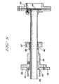
- FIG. 2 The structure shown in Figure 2 is essentially described from the inside out. More particularly, it is seen that centrally located electrical conductors 40 are disposed centrally within tube 41 preferably comprising stainless steel. Conductors 40 extend from exterior connector 75 to interior connector 70. Connector 70 is preferably provided with alignment pins to facilitate the connection. It is to be kept in mind that the entire assembly shown in Figure 2 is removable and functions to provide not only electrical connection to interior cryostat components, but also functions to minimize heat loss and to provide vapor cooling of the penetration components. Electrical conductors 40 between plugs 75 and 70 typically are provided to energize correction coil circuits. However, the main magnet coils are energized partly by means of electrically conductive lead 43 which is connected to lead 60 through airtight connection box 80.
- Conductor 43 possesses surface 50 which is preferably coated with an electrically conductive material which is soft at cryogenic temperatures, particularly with respect to the material employed in split ring 12.
- Electrical conductor 43 preferably comprises an elongate copper tube with grooves 49 disposed therein. These grooves along with grooves 48 described below, provide a helium vapor flowpath through the retractable lead assembly shown extending from the left side of box 80. These channels provide vapor cooling of the power leads. The flow of helium vapor through the main coil power leads is independently controlled by means of valves 81 and 82.
- a second main electrical conductor 45 is disposed coaxially about lead 43.
- leads 43 and 45 are insulated from one another by means of MYLAR8 sheath 44.
- This sheath, together with outer MYLARO sheath 47, also help to define coolant channels 48 and 49.
- the flow of helium vapor in these channels is better illustrated in Figure 3 below.
- tube 41 is also provided with an insulating layer 42 (see Figure 3).
- the correction coil power leads 40 typically comprise wires insulated with FORMVARS insulation and are disposed within central stainless steel tube 41. These wires are cooled by forced flow of helium, controlled by valve 83. Each end of the leads 40 is soldered to a lead in a conventional 32 pin connector. However, because of the small current rating for these leads, resistance heating at the low temperature connector contacts is acceptable despite the relatively high contact resistance.
- FIG. 3 A more detailed end view of the retractable lead shown in Figure 2 is provided in Figure 3.
- the arrangement, configuration and location of helium flow channels 48 and 49 are more readily visible.
- flow arrows 48' and 49' indicate the direction of flow of helium vapor through channels 48 and 49, respectively.
- surfaces 50 and 55 are coated with a metal conductor such as indium.
- the coating for these surfaces is selected to be one which exhibits low electrical contact resistance and yet is relatively soft at cryogenic temperatures. In operation, each of these surfaces is disposed through a clamp such as clamp 10 shown in Figure 1.
- each cam lever is provided with a pin (21 or 21').
- a special tool 30 having a notched L-shaped keyway 31 is made to engage the pin and to thereby effectuate pivotal motion of cam lever 20 or 20' about its corresponding axle. In this way, gap 19 is closed as the cam levers push against one side of the split ring the other side of which is affixed to block 11.
- Tool 30 preferably comprising a material such as brass is essentially half-cylindrical in shape. This configuration permits tool 30 to be rotated about its longitudinal axis so as to be able to engage both pins 21 and 21' (see Figure 1) through the sames access aperture.
- tool 30 is to be employed in a manner in which it extends through a cryostat wall, a somewhat more elaborate implement than that shown in Figure 4 is required.
- FIG 5 it is seen that tool 30 is disposed and brazed within hollow, conduit 32 preferably comprising stainless steel.
- Conduit 32 extends through cryostat.wall 38 and mounting flange 36 and is sealed therein by means of O-ring 39.
- Conduit 32 is slidable within flange 36 and can therefore be maneuvered to engage pins 21 or 21' as described above. In particular, if one or the other of these two pins is to be engaged, tool 30 is rotated through an angle of 180° and axially repositioned to engage the pin desired.
- Mounting flange 36 includes tapered slotted nipple 36'. Tightening flange 37 is turned on nipple 36' to lock tube 32 in position. Tube 32 also. preferably includes ejectable thermal insulation means (not shown) disposed therein. 0-ring 33 also seals tube 32 in flange 36. Furthermore, conduit 32 in which tool 30 is disposed includes a sealing flange 35 which contains rupture disk 34 to provide pressure relief against overpressure conditions that could result, for example, from magnet quench or cryostat vacuum loss. Any thermal insulation material in tube 32 is then ejected.
- the clamp and electrical lead assembly of the present invention provide a reliable mechanism for providing electrical contact between leads at low temperature conditions. It is furthermore seen that the apparatus of the present invention may be employed repeatedly without significant contact degradation. It is also seen herein that the present apparatus facilitates utilization of retractable leads in the construction of superconducting magnets, particularly those used in NMR medical diagnostic imaging. It is also seen that the present invention provides a tool which is readily insertable into a cryostat to engage the clamp mechanism of the present invention. Furthermore, even though the materials desired for use in the present invention must meet a stringent set of requirements with respect to conductivity, hardness and compatability at low temperatures, the apparatus of the present invention is nonetheless readily fabricatable at a relatively low cost.
Landscapes
- Physics & Mathematics (AREA)
- Condensed Matter Physics & Semiconductors (AREA)
- General Physics & Mathematics (AREA)
- Magnetic Resonance Imaging Apparatus (AREA)
- Containers, Films, And Cooling For Superconductive Devices (AREA)
Applications Claiming Priority (2)
| Application Number | Priority Date | Filing Date | Title |
|---|---|---|---|
| US621330 | 1984-06-15 | ||
| US06/621,330 US4614393A (en) | 1984-06-15 | 1984-06-15 | Retractable lead system for operation at cryogenic temperatures |
Publications (2)
| Publication Number | Publication Date |
|---|---|
| EP0168612A2 true EP0168612A2 (fr) | 1986-01-22 |
| EP0168612A3 EP0168612A3 (fr) | 1988-09-21 |
Family
ID=24489730
Family Applications (1)
| Application Number | Title | Priority Date | Filing Date |
|---|---|---|---|
| EP85106897A Withdrawn EP0168612A3 (fr) | 1984-06-15 | 1985-06-04 | Système conducteur rétractible pour opération à températures cryogéniques |
Country Status (5)
| Country | Link |
|---|---|
| US (1) | US4614393A (fr) |
| EP (1) | EP0168612A3 (fr) |
| JP (1) | JPS6145576A (fr) |
| CA (1) | CA1233209A (fr) |
| IL (1) | IL74916A0 (fr) |
Cited By (1)
| Publication number | Priority date | Publication date | Assignee | Title |
|---|---|---|---|---|
| EP0312896A3 (fr) * | 1987-10-19 | 1989-12-06 | General Electric Company | Connection cryogénique à commande hydraulique |
Families Citing this family (5)
| Publication number | Priority date | Publication date | Assignee | Title |
|---|---|---|---|---|
| US4872322A (en) * | 1988-09-02 | 1989-10-10 | General Electric Company | Power operated contact apparatus for superconductive circuit |
| WO1995005687A1 (fr) * | 1993-08-12 | 1995-02-23 | Barry Thomson Bowater | Borne de connexion pour batterie |
| US6045396A (en) * | 1997-09-12 | 2000-04-04 | Trw Inc. | Flex cable connector for cryogenic application |
| DE102004053516A1 (de) * | 2004-10-29 | 2006-05-11 | Atmel Germany Gmbh | Steckverbindungsmodule einer Steckverbindung zum gleichzeitigen Verbinden einer Vielzahl elektrischer Kontakte |
| US9182464B2 (en) | 2012-07-27 | 2015-11-10 | General Electric Company | Retractable current lead |
Family Cites Families (8)
| Publication number | Priority date | Publication date | Assignee | Title |
|---|---|---|---|---|
| US1904241A (en) * | 1926-12-31 | 1933-04-18 | Kammerer Erwin | Compound metal stock |
| US1861451A (en) * | 1928-04-04 | 1932-06-07 | Allan J Park | Connecter for batteries and similar devices |
| US1936469A (en) * | 1930-06-30 | 1933-11-21 | Gen Electric | Primary disconnecting device |
| US2864071A (en) * | 1954-02-11 | 1958-12-09 | Jr Frank E Johnson | Clamping device for electric wires |
| US2975394A (en) * | 1958-04-28 | 1961-03-14 | Renault | Battery terminal cable connectors |
| US3491329A (en) * | 1967-05-29 | 1970-01-20 | Gerald W Lecocq | Releasable electrical terminal |
| US3846742A (en) * | 1973-08-02 | 1974-11-05 | Gen Electric | Quick demountable load tap changer terminal |
| JPS542830Y2 (fr) * | 1975-08-12 | 1979-02-07 |
-
1984
- 1984-06-15 US US06/621,330 patent/US4614393A/en not_active Expired - Fee Related
-
1985
- 1985-04-16 IL IL74916A patent/IL74916A0/xx unknown
- 1985-06-04 EP EP85106897A patent/EP0168612A3/fr not_active Withdrawn
- 1985-06-12 JP JP60126394A patent/JPS6145576A/ja active Pending
- 1985-06-14 CA CA000484021A patent/CA1233209A/fr not_active Expired
Cited By (1)
| Publication number | Priority date | Publication date | Assignee | Title |
|---|---|---|---|---|
| EP0312896A3 (fr) * | 1987-10-19 | 1989-12-06 | General Electric Company | Connection cryogénique à commande hydraulique |
Also Published As
| Publication number | Publication date |
|---|---|
| EP0168612A3 (fr) | 1988-09-21 |
| JPS6145576A (ja) | 1986-03-05 |
| US4614393A (en) | 1986-09-30 |
| CA1233209A (fr) | 1988-02-23 |
| IL74916A0 (en) | 1985-08-30 |
Similar Documents
| Publication | Publication Date | Title |
|---|---|---|
| EP0209134B1 (fr) | Dispositif de bobine à supraconduction avec refroidissement par circulation forcée | |
| EP0596249B1 (fr) | Système à aimant supra-conducteur sans helium liquide | |
| US5686876A (en) | Superconducting magnet apparatus | |
| US20080115510A1 (en) | Cryostats including current leads for electronically powered equipment | |
| EP3401930B1 (fr) | Ensemble câble supraconducteur flexible | |
| US4614393A (en) | Retractable lead system for operation at cryogenic temperatures | |
| US4635450A (en) | Compact retractable cryogenic leads | |
| EP2439754A1 (fr) | Aimant supraconducteur à refroidissement de réfrigérateur | |
| US20080227647A1 (en) | Current lead with high temperature superconductor for superconducting magnets in a cryostat | |
| US4528532A (en) | Switch for fine adjustment of persistent current loops in superconductive circuits | |
| EP0285147B1 (fr) | Conduite transporteuse de courant | |
| US4813244A (en) | Hydraulically actuated cryogenic leads | |
| US9530549B2 (en) | Superconducting coil device with switchable conductor section and method for switching | |
| CA1228396A (fr) | Branchement pour dispositif supraconducteur, plus particulierement un aimant | |
| EP0357449A2 (fr) | Dispositif de contact pour circuit à supraconduction | |
| US5563369A (en) | Current lead | |
| US12073992B2 (en) | Current leads for superconducting magnets | |
| US5099215A (en) | Coupling device for a superconducting magnet | |
| US5590536A (en) | Bypass cryogenic current leads employing high temperature superconductors | |
| US3518591A (en) | Superconducting magnet and method of operation | |
| US5291168A (en) | Connector cooling and protection for power coupling assembly for superconducting magnets | |
| EP4530655A1 (fr) | Connecteur pour un système de connecteur d'un appareil d'examen par résonance magnétique | |
| US3530682A (en) | Foil wrapped superconducting magnet | |
| JPH01133307A (ja) | 低温機器 | |
| Zhao et al. | Superconducting properties of getter sputtered Mo sub (1-x) Si sub (x) films. |
Legal Events
| Date | Code | Title | Description |
|---|---|---|---|
| PUAI | Public reference made under article 153(3) epc to a published international application that has entered the european phase |
Free format text: ORIGINAL CODE: 0009012 |
|
| AK | Designated contracting states |
Designated state(s): CH DE FR GB IT LI NL SE |
|
| PUAL | Search report despatched |
Free format text: ORIGINAL CODE: 0009013 |
|
| STAA | Information on the status of an ep patent application or granted ep patent |
Free format text: STATUS: THE APPLICATION IS DEEMED TO BE WITHDRAWN |
|
| AK | Designated contracting states |
Kind code of ref document: A3 Designated state(s): CH DE FR GB IT LI NL SE |
|
| 18D | Application deemed to be withdrawn |
Effective date: 19870701 |
|
| RIN1 | Information on inventor provided before grant (corrected) |
Inventor name: LASKARIS, EVANGELOS TRIFON |