EP0168679A2 - Système de mesure du rayonnement électromagnétique venant de l'espace semi-infini - Google Patents
Système de mesure du rayonnement électromagnétique venant de l'espace semi-infini Download PDFInfo
- Publication number
- EP0168679A2 EP0168679A2 EP85107750A EP85107750A EP0168679A2 EP 0168679 A2 EP0168679 A2 EP 0168679A2 EP 85107750 A EP85107750 A EP 85107750A EP 85107750 A EP85107750 A EP 85107750A EP 0168679 A2 EP0168679 A2 EP 0168679A2
- Authority
- EP
- European Patent Office
- Prior art keywords
- modulators
- radiation
- dome
- space
- highly sensitive
- Prior art date
- Legal status (The legal status is an assumption and is not a legal conclusion. Google has not performed a legal analysis and makes no representation as to the accuracy of the status listed.)
- Granted
Links
Images


Classifications
-
- G—PHYSICS
- G01—MEASURING; TESTING
- G01J—MEASUREMENT OF INTENSITY, VELOCITY, SPECTRAL CONTENT, POLARISATION, PHASE OR PULSE CHARACTERISTICS OF INFRARED, VISIBLE OR ULTRAVIOLET LIGHT; COLORIMETRY; RADIATION PYROMETRY
- G01J1/00—Photometry, e.g. photographic exposure meter
- G01J1/02—Details
- G01J1/04—Optical or mechanical part supplementary adjustable parts
-
- G—PHYSICS
- G01—MEASURING; TESTING
- G01J—MEASUREMENT OF INTENSITY, VELOCITY, SPECTRAL CONTENT, POLARISATION, PHASE OR PULSE CHARACTERISTICS OF INFRARED, VISIBLE OR ULTRAVIOLET LIGHT; COLORIMETRY; RADIATION PYROMETRY
- G01J1/00—Photometry, e.g. photographic exposure meter
- G01J1/02—Details
- G01J1/04—Optical or mechanical part supplementary adjustable parts
- G01J1/0407—Optical elements not provided otherwise, e.g. manifolds, windows, holograms, gratings
-
- G—PHYSICS
- G01—MEASURING; TESTING
- G01J—MEASUREMENT OF INTENSITY, VELOCITY, SPECTRAL CONTENT, POLARISATION, PHASE OR PULSE CHARACTERISTICS OF INFRARED, VISIBLE OR ULTRAVIOLET LIGHT; COLORIMETRY; RADIATION PYROMETRY
- G01J1/00—Photometry, e.g. photographic exposure meter
- G01J1/02—Details
- G01J1/04—Optical or mechanical part supplementary adjustable parts
- G01J1/0407—Optical elements not provided otherwise, e.g. manifolds, windows, holograms, gratings
- G01J1/044—Optical elements not provided otherwise, e.g. manifolds, windows, holograms, gratings using shutters
-
- G—PHYSICS
- G01—MEASURING; TESTING
- G01J—MEASUREMENT OF INTENSITY, VELOCITY, SPECTRAL CONTENT, POLARISATION, PHASE OR PULSE CHARACTERISTICS OF INFRARED, VISIBLE OR ULTRAVIOLET LIGHT; COLORIMETRY; RADIATION PYROMETRY
- G01J5/00—Radiation pyrometry, e.g. infrared or optical thermometry
- G01J5/02—Constructional details
- G01J5/08—Optical arrangements
- G01J5/0803—Arrangements for time-dependent attenuation of radiation signals
- G01J5/0805—Means for chopping radiation
-
- G—PHYSICS
- G01—MEASURING; TESTING
- G01J—MEASUREMENT OF INTENSITY, VELOCITY, SPECTRAL CONTENT, POLARISATION, PHASE OR PULSE CHARACTERISTICS OF INFRARED, VISIBLE OR ULTRAVIOLET LIGHT; COLORIMETRY; RADIATION PYROMETRY
- G01J1/00—Photometry, e.g. photographic exposure meter
- G01J1/02—Details
- G01J1/0252—Constructional arrangements for compensating for fluctuations caused by, e.g. temperature, or using cooling or temperature stabilization of parts of the device; Controlling the atmosphere inside a photometer; Purge systems, cleaning devices
-
- G—PHYSICS
- G01—MEASURING; TESTING
- G01J—MEASUREMENT OF INTENSITY, VELOCITY, SPECTRAL CONTENT, POLARISATION, PHASE OR PULSE CHARACTERISTICS OF INFRARED, VISIBLE OR ULTRAVIOLET LIGHT; COLORIMETRY; RADIATION PYROMETRY
- G01J1/00—Photometry, e.g. photographic exposure meter
- G01J1/02—Details
- G01J1/04—Optical or mechanical part supplementary adjustable parts
- G01J1/0488—Optical or mechanical part supplementary adjustable parts with spectral filtering
-
- G—PHYSICS
- G01—MEASURING; TESTING
- G01J—MEASUREMENT OF INTENSITY, VELOCITY, SPECTRAL CONTENT, POLARISATION, PHASE OR PULSE CHARACTERISTICS OF INFRARED, VISIBLE OR ULTRAVIOLET LIGHT; COLORIMETRY; RADIATION PYROMETRY
- G01J1/00—Photometry, e.g. photographic exposure meter
- G01J1/42—Photometry, e.g. photographic exposure meter using electric radiation detectors
- G01J2001/4266—Photometry, e.g. photographic exposure meter using electric radiation detectors for measuring solar light
- G01J2001/4285—Pyranometer, i.e. integrating over space
Definitions
- the invention relates to a device for measuring the electromagnetic radiation coming from the half-space (corresponding to a solid angle of 2 ⁇ ).
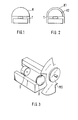
- Such devices have, for example, as indicated schematically in FIGS. 1 and 2, a thermal column T, the horizontally arranged, active soldering points of which are blackened and isolated from the other parts of the device.
- a thermal column T the horizontally arranged, active soldering points of which are blackened and isolated from the other parts of the device.
- the temperature of the active solder joints increases compared to the temperature of the passive solder joints, which are thermally connected to a relatively large mass of the device.
- the resulting thermal voltage is, if necessary together with other measurands, such as the temperature of the passive solder joints, a measure of the incident radiation.
- thermopile T is generally protected by a so-called draft shield K, which is made of a material that is permeable to the radiation to be measured, such as glass, polyethylene, and the like
- draft shield K which is made of a material that is permeable to the radiation to be measured, such as glass, polyethylene, and the like
- two hemispherical domes Kl and K2 are arranged around the thermopile T in another conventional embodiment, which are also made of a material which is transparent to the radiation to be measured.
- a radiation detector is used D, which has a high sensitivity and a very low inertia, such as a semiconductor bolometer, a photo element or a pyroelectric detector, is attached behind a vibrating or rotating modulator disc MS, which then alternately releases the detector D for the radiation to be measured or it covers.
- a lens arrangement 0 is provided in front of the detector for focusing the radiation.
- an alternating voltage or an alternating current is generated at the detector D, which corresponds to the radiation difference between a measuring radiation and the radiation emitted and / or reflected by the modulator disc MS (the so-called comparison radiation).
- the advantage of this method is that emission changes within the system (namely on the detector, housing, window or the optics), which are caused for example by temperature changes, have the same effect on the measuring and comparison radiation and consequently on the AC voltage or the AC can not be impressed.
- the disadvantage here is that the radiation emitted and / or reflected by the modulator disc MS must be known, since it represents the reference signal (the zero signal).
- the disadvantages of the conventional devices are to be largely eliminated and a device for measuring the electromagnetic radiation coming from the half-space (corresponding to a solid angle 27T) is to be created, with which a significantly higher measurement accuracy than the so-called constant light method can be achieved, and which works with less inertia compared to the conventional constant light method.
- this is achieved in a device for measuring the electromagnetic radiation coming from the half-space by the subject matter of claim 1.
- two identical or differently designed, interleaved, segment-segment-shaped modulators are used, which, for example, enclose the dome K shown in FIG. If, in accordance with a preferred embodiment of the device according to the invention, one of the two modulators is fixed and the other rotates about a common, vertical axis, a modulation took place, which is carried out on one or more horizontally oriented, highly sensitive detectors, for example in the form of bolometers or photo elements AC voltage is generated, which would correspond to the difference between the half-space radiation and - provided impermeable, non-reflecting modulators - the intrinsic radiation of the modulator.
- highly sensitive detectors for example in the form of bolometers or photo elements
- both dome-shaped modulators must then rotate about their common vertical axis, either in opposite directions at different speeds or in opposite directions at the same or different speeds.
- 50% of the half-space is then also covered, however, in a constant change, so that the entire half-space is covered on average over several periods.
- the modulation frequency can largely be adapted to the special measuring task by the choice of the sector shape and number as well as by the speed of rotation; the same applies to the transmission, emissivity or reflectivity of the modulator.
- the two dome-segment-shaped modulators have a precisely defined transmission, emission and / or reflectivity, which is preferably wavelength-dependent.
- the device according to the invention for measuring the electromagnetic radiation coming from the half-space is considerably less inertia.
- FIG. 4 a and 4 b show a partially cut-away, schematic representation or a perspective representation of a preferred embodiment of a device for carrying out the method according to the invention, which is recommended for meteorological applications and is broken down into individual parts.
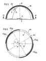
- FIG. 5 shows a schematic vertical sectional view and in FIG. 6 in section schematically in a top view.
- One or more low-inertia, highly sensitive detectors D are preferably arranged symmetrically with respect to the center of the spherical cap M under the radiation-permeable spherical cap K.
- the calotte K is enclosed by two uniformly arranged modulators M1 and M2, which are preferably designed as calotte segment-shaped, wing-like sections KZ M1 and KZ M2 .
- the two dome segment-shaped modulators, M1 and M2 are arranged such that at least one modulator rotates about their common, vertical axis A.
- modulators M1 and M2 are driven in such a way that they either rotate at different speeds in the same direction or rotate in opposite directions about the common vertical axis A.
- the drive of the two dome segment-shaped modulators M1 and M2 could take place via sprockets Z1 and Z2, which are not shown in more detail, which, for example, at the free lower end on the outside of the outer dome segment-shaped modulator Ml or at the lower free end on the inside of the inner, dome segment-shaped modulator M2 are trained.
- the rotational movement can be transmitted from the inner to the outer ring gear or vice versa, for example via one or more gears provided in between .
- the two modulators M1 and M2 are each, for example, each formed as two sections KZ M1 and KZ M2 of spherical corners or of segments of non-closed hemispheres in such a way that that the two sections KZ M1 and KZ M2 correspond to sections of the surfaces of ball wedges, which are formed by two planes passing through the center of the ball M, which intersect at an internal angle ⁇ , the angle being preferred in the embodiment shown in FIG is equal to 90 °.
- the sections KZ M1 and KZ M2 provided on the surfaces of the dome segment-shaped modulators M1 and M2 are preferably black.
- the temperature of the dome-segment-shaped modulators M1 and M2 is measured by high-resistance elements TH, for example in the form of thermistors, the electrical voltage, for example is removed via slip rings. In any case, this temperature measurement is only necessary if measurements in the thermal infrared range above a wavelength of approximately 3 ⁇ m are to be made.
- the temperature of the black sections KZ M1 and KZ M2 of the two modulators M1 and M2 does not play an important role in measurements below a wavelength of 3 ⁇ m.
- the modulators M1 and M2 can be made, for example, of glass, which is opaque to radiation with a wavelength above 3 ⁇ m, while the dome consists of a material which is transparent and above a wavelength of 3 ⁇ m can be transparent even below a wavelength of 3 ⁇ m. In this way, only the radiation above a wavelength of 3 ⁇ m is detected as a result of the modulation.
- the space under the calotte K i.e. the space in which the highly sensitive, low-inertia detector D is arranged, for example be sealed gas-tight and filled with a gas that is suitable for the measurements in the respective wavelength range, i.e. in a wavelength range above and below 3 ⁇ m, particularly suitable.
Landscapes
- Physics & Mathematics (AREA)
- General Physics & Mathematics (AREA)
- Spectroscopy & Molecular Physics (AREA)
- Photometry And Measurement Of Optical Pulse Characteristics (AREA)
- Measurement Of Radiation (AREA)
- Radiation Pyrometers (AREA)
- Treatments For Attaching Organic Compounds To Fibrous Goods (AREA)
- Apparatus For Radiation Diagnosis (AREA)
Priority Applications (1)
| Application Number | Priority Date | Filing Date | Title |
|---|---|---|---|
| AT85107750T ATE40599T1 (de) | 1984-06-26 | 1985-06-22 | Einrichtung zur messung der aus dem halbraum kommenden, elektromagnetischen strahlung. |
Applications Claiming Priority (2)
| Application Number | Priority Date | Filing Date | Title |
|---|---|---|---|
| DE3423494A DE3423494C2 (de) | 1984-06-26 | 1984-06-26 | Einrichtung zur Messung der aus dem Halbraum kommenden elektromagnetischen Strahlung |
| DE3423494 | 1984-06-26 |
Publications (3)
| Publication Number | Publication Date |
|---|---|
| EP0168679A2 true EP0168679A2 (fr) | 1986-01-22 |
| EP0168679A3 EP0168679A3 (en) | 1986-09-17 |
| EP0168679B1 EP0168679B1 (fr) | 1989-02-01 |
Family
ID=6239161
Family Applications (1)
| Application Number | Title | Priority Date | Filing Date |
|---|---|---|---|
| EP85107750A Expired EP0168679B1 (fr) | 1984-06-26 | 1985-06-22 | Système de mesure du rayonnement électromagnétique venant de l'espace semi-infini |
Country Status (6)
| Country | Link |
|---|---|
| US (1) | US4928012A (fr) |
| EP (1) | EP0168679B1 (fr) |
| JP (1) | JPS6117918A (fr) |
| AT (1) | ATE40599T1 (fr) |
| AU (1) | AU561137B2 (fr) |
| DE (2) | DE3423494C2 (fr) |
Cited By (1)
| Publication number | Priority date | Publication date | Assignee | Title |
|---|---|---|---|---|
| EP0769688A4 (fr) * | 1995-05-08 | 1998-09-09 | Japan Energy Corp | Moniteur pour l'environnement |
Families Citing this family (8)
| Publication number | Priority date | Publication date | Assignee | Title |
|---|---|---|---|---|
| DE3445677A1 (de) * | 1984-12-14 | 1986-06-19 | Uranit GmbH, 5170 Jülich | Strahlungsmesssonde zur beruehrungslosen, emissionsgradunabhaengigen temperaturmessung |
| DE3708043A1 (de) * | 1987-03-12 | 1988-09-22 | Deutsche Forsch Luft Raumfahrt | Einrichtung zur messung der aus dem halbraum oder raum kommenden elektromagnetischen strahlung |
| DE3744182C2 (de) * | 1987-12-24 | 1994-06-30 | Asea Brown Boveri | Infrarotdetektor |
| US5134292A (en) * | 1989-02-07 | 1992-07-28 | Nippon Mining Co., Ltd. | Moving object detector and moving object detecting system |
| US6670538B2 (en) * | 2001-01-05 | 2003-12-30 | Endevco Corporation | Thermal radiation sensor |
| WO2007062839A1 (fr) * | 2005-11-30 | 2007-06-07 | Astrium Gmbh | Salle de mesure haute frequence pour effectuer des mesures sur des objets de grande taille |
| JP2010091368A (ja) * | 2008-10-07 | 2010-04-22 | Nippon Ceramic Co Ltd | サーモパイル型赤外線検出装置 |
| DE102012009080A1 (de) * | 2012-05-09 | 2013-11-14 | Gerald Mischke | THERMO-U, ein Integriertes HW-und SW-System zur Messung und Berechnung von Wärmeenergieverlusten, von Wärmewiderständen, effektiven Wärmekapazitäten sowie der zugehörigen thermischen Trägheitskonstanten von Oberflächen (von Bauteilen) von Geräten, Anlagen, Gebäuden, etc. |
Family Cites Families (9)
| Publication number | Priority date | Publication date | Assignee | Title |
|---|---|---|---|---|
| US2994053A (en) * | 1960-05-24 | 1961-07-25 | Barnes Eng Co | Selective bolometer |
| US3097300A (en) * | 1960-10-06 | 1963-07-09 | Barnes Eng Co | Thermal detector and reference source |
| US3390576A (en) * | 1965-09-28 | 1968-07-02 | John I. Yellott | Solar radiation measuring device |
| DE1573283B1 (de) * | 1965-10-07 | 1971-11-11 | North American Aviation Inc | Radiometer |
| US3563658A (en) * | 1965-10-22 | 1971-02-16 | Philips Corp | Spectroradiometer for detecting atmospheric contaminants |
| SE339054B (fr) * | 1970-02-03 | 1971-09-27 | Aga Ab | |
| US3794838A (en) * | 1972-02-10 | 1974-02-26 | Barnes Eng Co | Compensation means for ambient temperature changes of a radiation chopper in a radiometer |
| IT1102906B (it) * | 1978-11-07 | 1985-10-14 | Durst Fabbrica Macchine Ed App | Fotometro |
| US4322124A (en) * | 1980-05-05 | 1982-03-30 | Honeywell Inc. | Low cost wide field of view infrared sensor |
-
1984
- 1984-06-26 DE DE3423494A patent/DE3423494C2/de not_active Expired
-
1985
- 1985-06-22 AT AT85107750T patent/ATE40599T1/de active
- 1985-06-22 EP EP85107750A patent/EP0168679B1/fr not_active Expired
- 1985-06-22 DE DE8585107750T patent/DE3568082D1/de not_active Expired
- 1985-06-24 AU AU43978/85A patent/AU561137B2/en not_active Ceased
- 1985-06-26 JP JP60140115A patent/JPS6117918A/ja active Granted
-
1989
- 1989-10-19 US US07/425,512 patent/US4928012A/en not_active Expired - Fee Related
Cited By (1)
| Publication number | Priority date | Publication date | Assignee | Title |
|---|---|---|---|---|
| EP0769688A4 (fr) * | 1995-05-08 | 1998-09-09 | Japan Energy Corp | Moniteur pour l'environnement |
Also Published As
| Publication number | Publication date |
|---|---|
| DE3423494A1 (de) | 1986-01-16 |
| JPS6117918A (ja) | 1986-01-25 |
| US4928012A (en) | 1990-05-22 |
| EP0168679B1 (fr) | 1989-02-01 |
| ATE40599T1 (de) | 1989-02-15 |
| JPH0476419B2 (fr) | 1992-12-03 |
| DE3423494C2 (de) | 1986-09-04 |
| EP0168679A3 (en) | 1986-09-17 |
| AU4397885A (en) | 1986-01-02 |
| DE3568082D1 (en) | 1989-03-09 |
| AU561137B2 (en) | 1987-04-30 |
Similar Documents
| Publication | Publication Date | Title |
|---|---|---|
| EP0536727B1 (fr) | Senseur multispectral | |
| DE2653110C3 (de) | Infrarotstrahlungs-Einbruchdetektor | |
| DE19713928C1 (de) | Meßvorrichtung zur Infrarotabsorption | |
| DE2916768C2 (de) | Optische Anordnung für einen passiven Infrarot-Bewegungsmelder | |
| EP0168679B1 (fr) | Système de mesure du rayonnement électromagnétique venant de l'espace semi-infini | |
| DE4128912C2 (de) | Verfahren und Einrichtung zur Kalibrierung von Spektralradiometern | |
| DE2618976B2 (de) | Optisches Zielbeobachtungsgerät | |
| DE69002707T2 (de) | Mit einer bewegbaren Vorrichtung verbundener Apparat zur Erfassung von Signalen, die der Geschwindigkeit dieser Vorrichtung in einem Fluidum entsprechen sowie Messgerät mit einer solchen Vorrichtung. | |
| DE3119720A1 (de) | Bewegungsmelder zur raumueberwachung | |
| DE3235250C3 (de) | Facettenoptik zum Erfassen von Strahlung aus einem großen Raumwinkel, insbesondere für Bewegungsmelder | |
| DE3211046A1 (de) | Optische abtastanordnung | |
| DE3805642C1 (fr) | ||
| DE2344754C3 (de) | Abtastanordnung | |
| EP0050750B1 (fr) | Détecteur d'intrusion à infrarouge | |
| EP0558796B1 (fr) | Senseur optique | |
| EP0282029B1 (fr) | Dispositif de mesure de rayonnement électromagnétique demi-spatial ou spatial | |
| DE1473249B1 (de) | Infrarotstrahlungsdetektor | |
| DE4134313C2 (de) | Infrarot-Meßverfahren und -Meßanordnung | |
| DE2041467A1 (de) | Vorrichtung zur Ermittlung turbulenter Luftstroemungen | |
| DE2454480B1 (de) | IR-Such- und Verfolgungsgeraet | |
| DE4221833A1 (de) | Ungluecksverhuetende erfassungsvorrichtung mit waermebild-erfassungseinrichtung | |
| DD141200A1 (de) | Waermestrahlungsmesser und waermestrahlungsmesssystem | |
| DE2749229C2 (de) | Nichtdispersives Infrarot-Gasanalysengerät | |
| DE3922017A1 (de) | Optische sensoreinrichtung | |
| DE69202745T2 (de) | Infrarote-Detektierungsvorrichtung. |
Legal Events
| Date | Code | Title | Description |
|---|---|---|---|
| PUAI | Public reference made under article 153(3) epc to a published international application that has entered the european phase |
Free format text: ORIGINAL CODE: 0009012 |
|
| AK | Designated contracting states |
Designated state(s): AT BE CH DE FR GB IT LI LU NL SE |
|
| PUAL | Search report despatched |
Free format text: ORIGINAL CODE: 0009013 |
|
| AK | Designated contracting states |
Kind code of ref document: A3 Designated state(s): AT BE CH DE FR GB IT LI LU NL SE |
|
| RHK1 | Main classification (correction) |
Ipc: G01J 5/62 |
|
| 17P | Request for examination filed |
Effective date: 19861219 |
|
| 17Q | First examination report despatched |
Effective date: 19880114 |
|
| GRAA | (expected) grant |
Free format text: ORIGINAL CODE: 0009210 |
|
| AK | Designated contracting states |
Kind code of ref document: B1 Designated state(s): AT BE CH DE FR GB IT LI LU NL SE |
|
| REF | Corresponds to: |
Ref document number: 40599 Country of ref document: AT Date of ref document: 19890215 Kind code of ref document: T |
|
| ITF | It: translation for a ep patent filed | ||
| GBT | Gb: translation of ep patent filed (gb section 77(6)(a)/1977) | ||
| REF | Corresponds to: |
Ref document number: 3568082 Country of ref document: DE Date of ref document: 19890309 |
|
| ET | Fr: translation filed | ||
| PLBE | No opposition filed within time limit |
Free format text: ORIGINAL CODE: 0009261 |
|
| STAA | Information on the status of an ep patent application or granted ep patent |
Free format text: STATUS: NO OPPOSITION FILED WITHIN TIME LIMIT |
|
| 26N | No opposition filed | ||
| ITTA | It: last paid annual fee | ||
| EPTA | Lu: last paid annual fee | ||
| EAL | Se: european patent in force in sweden |
Ref document number: 85107750.3 |
|
| PGFP | Annual fee paid to national office [announced via postgrant information from national office to epo] |
Ref country code: GB Payment date: 19990604 Year of fee payment: 15 |
|
| PGFP | Annual fee paid to national office [announced via postgrant information from national office to epo] |
Ref country code: FR Payment date: 19990616 Year of fee payment: 15 |
|
| PGFP | Annual fee paid to national office [announced via postgrant information from national office to epo] |
Ref country code: SE Payment date: 19990621 Year of fee payment: 15 Ref country code: LU Payment date: 19990621 Year of fee payment: 15 Ref country code: CH Payment date: 19990621 Year of fee payment: 15 Ref country code: BE Payment date: 19990621 Year of fee payment: 15 Ref country code: AT Payment date: 19990621 Year of fee payment: 15 |
|
| PGFP | Annual fee paid to national office [announced via postgrant information from national office to epo] |
Ref country code: NL Payment date: 19990622 Year of fee payment: 15 |
|
| PG25 | Lapsed in a contracting state [announced via postgrant information from national office to epo] |
Ref country code: LU Free format text: LAPSE BECAUSE OF NON-PAYMENT OF DUE FEES Effective date: 20000622 Ref country code: GB Free format text: LAPSE BECAUSE OF NON-PAYMENT OF DUE FEES Effective date: 20000622 Ref country code: AT Free format text: LAPSE BECAUSE OF NON-PAYMENT OF DUE FEES Effective date: 20000622 |
|
| PG25 | Lapsed in a contracting state [announced via postgrant information from national office to epo] |
Ref country code: SE Free format text: LAPSE BECAUSE OF NON-PAYMENT OF DUE FEES Effective date: 20000623 |
|
| PG25 | Lapsed in a contracting state [announced via postgrant information from national office to epo] |
Ref country code: LI Free format text: LAPSE BECAUSE OF NON-PAYMENT OF DUE FEES Effective date: 20000630 Ref country code: CH Free format text: LAPSE BECAUSE OF NON-PAYMENT OF DUE FEES Effective date: 20000630 Ref country code: BE Free format text: LAPSE BECAUSE OF NON-PAYMENT OF DUE FEES Effective date: 20000630 |
|
| BERE | Be: lapsed |
Owner name: DEUTSCHE FORSCHUNGS- UND VERSUCHSANSTALT FUR LUFT Effective date: 20000630 |
|
| PG25 | Lapsed in a contracting state [announced via postgrant information from national office to epo] |
Ref country code: NL Free format text: LAPSE BECAUSE OF NON-PAYMENT OF DUE FEES Effective date: 20010101 |
|
| GBPC | Gb: european patent ceased through non-payment of renewal fee |
Effective date: 20000622 |
|
| REG | Reference to a national code |
Ref country code: CH Ref legal event code: PL |
|
| EUG | Se: european patent has lapsed |
Ref document number: 85107750.3 |
|
| PG25 | Lapsed in a contracting state [announced via postgrant information from national office to epo] |
Ref country code: FR Free format text: LAPSE BECAUSE OF NON-PAYMENT OF DUE FEES Effective date: 20010228 |
|
| NLV4 | Nl: lapsed or anulled due to non-payment of the annual fee |
Effective date: 20010101 |
|
| REG | Reference to a national code |
Ref country code: FR Ref legal event code: ST |
|
| PGFP | Annual fee paid to national office [announced via postgrant information from national office to epo] |
Ref country code: DE Payment date: 20020528 Year of fee payment: 18 |
|
| PG25 | Lapsed in a contracting state [announced via postgrant information from national office to epo] |
Ref country code: DE Free format text: LAPSE BECAUSE OF NON-PAYMENT OF DUE FEES Effective date: 20040101 |