EP0168712A1 - Moteur rotatif à aimants permanents - Google Patents
Moteur rotatif à aimants permanents Download PDFInfo
- Publication number
- EP0168712A1 EP0168712A1 EP85108194A EP85108194A EP0168712A1 EP 0168712 A1 EP0168712 A1 EP 0168712A1 EP 85108194 A EP85108194 A EP 85108194A EP 85108194 A EP85108194 A EP 85108194A EP 0168712 A1 EP0168712 A1 EP 0168712A1
- Authority
- EP
- European Patent Office
- Prior art keywords
- magnets
- rotor
- motor
- auxiliary
- rotors
- Prior art date
- Legal status (The legal status is an assumption and is not a legal conclusion. Google has not performed a legal analysis and makes no representation as to the accuracy of the status listed.)
- Withdrawn
Links
- 238000006243 chemical reaction Methods 0.000 claims abstract description 19
- 238000005096 rolling process Methods 0.000 claims abstract description 5
- 230000000694 effects Effects 0.000 claims description 17
- 230000033001 locomotion Effects 0.000 claims description 12
- 230000005540 biological transmission Effects 0.000 claims description 9
- 230000001133 acceleration Effects 0.000 description 6
- 230000006866 deterioration Effects 0.000 description 2
- 238000004880 explosion Methods 0.000 description 2
- 238000002485 combustion reaction Methods 0.000 description 1
- 230000005611 electricity Effects 0.000 description 1
- 239000000446 fuel Substances 0.000 description 1
- 238000012423 maintenance Methods 0.000 description 1
- 230000009347 mechanical transmission Effects 0.000 description 1
- 238000000034 method Methods 0.000 description 1
- 238000012986 modification Methods 0.000 description 1
- 230000004048 modification Effects 0.000 description 1
- 239000003209 petroleum derivative Substances 0.000 description 1
- 230000000750 progressive effect Effects 0.000 description 1
- 230000009466 transformation Effects 0.000 description 1
Images


Classifications
-
- H—ELECTRICITY
- H02—GENERATION; CONVERSION OR DISTRIBUTION OF ELECTRIC POWER
- H02K—DYNAMO-ELECTRIC MACHINES
- H02K53/00—Alleged dynamo-electric perpetua mobilia
Definitions
- This invention relates to a rotary permanent magnet motor. More particularly, the invention relates to a rotary permanent magnet motor comprising a main rotor, a series of auxiliary rotors and a magnetic band, and which is of such configuration and characteristics as to give it considerable advantages over motors of the known art.
- Any known motor whether of the explosion electric or any other type, needs a continuous supply of energy for its operation, this being in the form of fuel, electrical energy etc.
- the motor according to the invention operates exclusively by means of permanent magnets and has no need for a continuous energy supply, and thus constitutes a perfect energy producer which obviates all the aforesaid costs and deterioration.
- Appropriate equipment receives the mains current and, by means of a series of transformers and relays, feeds the motor with the most appropriate voltage for its starting, stopping, acceleration, braking of reversal of motion.
- Electricity generating sets satisfy these requirements by using internal combustion engines, but are too noisy.
- the present invention obviates the aforesaid drawbacks and provides other considerable advantages as illustrated hereinafter.
- the rotary permanent magnet motor according to the present invention is characterised by comprising a main rotor, a series of auxiliary rotors and a magnetic band, said auxiliary rotors and said magnetic band being divided into radial magnetic sectors arranged to be points of thrust or of attraction by which the rolling of said auxiliary rotors on the magnetic band, on the inside or outside of it, is effected by utilising the lead or lag between the magnets of the band and those of the auxiliary rotors, thus determining the axial rotation of the main rotor, the barycentre of reaction of said auxiliary rotors passing external or internal to the barycentre of the magnets, said motor being of cylindrical, frusto-conical or other shape.
- said main rotor supports at equal angular distance apart, said cylindrical or frusto-conical auxiliary rotors, each composed of radial sectors of even number formed from permanent magnets disposed in a chequered arrangement of alternate opposite polarity, said auxiliary rotors being disposed internal or external to said cylindrical or frusto-conical magnetic band, which is likewise composed of a series of radial sectors of even number formed from permanent magnets alternately of opposite polarity.
- the rotors are linked together and to the fixed casing of the motor so that the rotation of the main rotor takes place by the effect of the motion of each auxiliary rotor, almost equivalent to the rolling motion on the cylindrical surface of the magnetic band, either on the inside or on the outside of it.
- each auxlliary rotor encountering supporting reaction by way of its pinion, rotates about itself and translates relative to the band, to cause the main rotor to undergo axial rotation.
- Each rotor is connected to the other rotors by way of-planet gears rigid with their shafts and an endless chain, or by a sun gear which engages with said planet gears or by other equivalent linkages.
- At least one of the cylindrical auxiliary rotors is connected to the fixed casing supporting the transmission shaft by an endless chain which engages both with a gear wheel rigid with the rotor shaft and with a ring gear rigid with the casing and coaxial to the main rotor.
- the transmission ratio is equivalent to the ratio of the rotor diameters to the magnetic band diameter.
- the magnetic band can be located in any angular position with respect to the main rotor assembly with wich the shafts of the auxiliary rotors are rigid, which enables the positive or negative magnets of the band to be positioned at will opposite the positive magnets of the auxiliary rotors or vice versa, ie with the magnets mutually centered or in any intermediate offset position between the various centered positions.
- the magnetic band is moved by a suitable external lever or equivalent means.
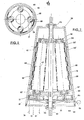
- auxiliary rotor shafts are mechanically connected together at one end by a chain 23, by way of the sprocket pinions 24 keyed on, to each auxiliary rotor.
- One of these rotors carries a supplementary sprocket pinion 25 which by means of the chain 28 is connected to the ring gear 26, which is fixed to the cover 13 by screws 27.
- the magnet holding ring 29 is set into the centre of the stator, it being controlled from the outside by the lever 30.
- the magnet holding ring carries internally a series of permanent magnets 31 of positive polarity spaced apart by a series of permanent magnets 32 of negative polarity ( Figure 2), to thus constitute a magnetic band.
- Each of the auxiliary rotors also carries a series of magnets of positive polarity 33 spaced apart by a series of magnets of negative polarity 34.
- the width and length of the positive polarity magnets is equal to those of the negative polarity magnets, and the width and length of the magnets disposed on the stator correspond to those of the magnets fitted on to each auxiliary rotor.
- the number of magnets fitted to the stator and the number of magnets mounted on each auxiliary rotor are determined in accordance with the motor size and power.
- the chains 23, 28 can be replaced by toothed belts or gears. In this latter case however, an idle gear must be interposed so that the directions of rotation are correct, as described hereinafter.
- the chain, belt or gear distribution system can be fitted to either end of the motor.
- the lever 30 which causes the ring 29 to rotate relative to the stator 10 is turned manually or by automatic means.
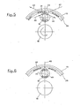
- the effect is that.the main rotor rotates right-handed because the force 36 applied at the barycentre of the positive magnet 33 opposes the force 37 applied at the barycentre of the magnet 31. This is because these are forces expressed by magnets of equal polarity.
- the force-40 expressed by the positive magnet 33 opposes the force 41 expressed by the magnet of equal polarity 31; the force 43 of the positive magnet 33 remains attracted by the magnet of reverse polarity which develops the force 42, so that the auxiliary rotor 19 accelerates its rotation in the left-handed direction, while the main rotor 16 accelerates its rotation in the right-handed direction.
- the centre of the positive magnet 33 situated on the auxiliary rotor 19 is made to correspond with the other end of the positive magnet 31 mounted on the stator, the force 44 opposes the force 45, and the foroe 46 remains attracted by the force 47, the effect being a right-handed rotation of the auxiliary rotors 19, and a corresponding left-handed rotation of the main rotor 16.
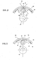
- the magnet motor comprises a conical stator 50 closed at one end by the cover 51, which is joined to the stator by a series of circumferehtial screws 52.
- a transmission shaft or main rotor 53 mounted on bearings 54, 55, supports one or more auxiliary rotors 56 mounted on support arms 57, 58 and rotating on bearings 59, 60 ( Figure 7).
- auxiliary rotor shafts are connected mechanically together at one end by a sun gear with internal conical toothing 61, by way of the bevel pinions 62 keyed on to each auxiliary rotor.
- An external lever 63 with a grip 64 emerging from the cavity 65 formed in the stator 50 is rigidly connected to the gear 61.
- the magnet holding ring rigidly carries a series of permanent magnets 68 of positive polarity spaces apart by a series of permanent magnets 69 of negative polarity ( Figure 8).
- the magnet arrangement is of the chequered type, ie below a first row 68' of positive and negative magnets disposed alternately on the circumference, there is an underlying row 69' of magnets which are offset by one polarity.
- Each of the auxiliary rotors also carries a series of positive polarity magnets 70 spaced apart by a series of negative polarity magnets 71, these also being disposed chequered as on the stator.
- the width and length of the positive polarity magnets is equal to those of the negative polarity magnets, both in the case of those fitted to the stator and in the case of those fitted to the auxiliary rotors.
- the number of magnets fitted to the stator and the number of magnets mounted on each auxiliary rotor is determined according to the motor size and its power.
- gear 61 and bevel pinions 62 can be replaced by toothed belts or chains. In these latter cases, care must be taken to make the directions of rotation correct, as described hereinafter.
- the chain, belt or gear distribution system can be fitted to either end of the motor.
- the linkage is housed in the lower taper of the stator.
- the components of the distribution system can be located in any position in which the three forces, namely the attraction, reaction and yielding force are separated from each other and are at different distances from the transmission shaft.
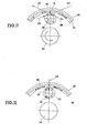
- Figure 9 shows the sun gear 72 mounted on the bearing 13 and controlled by the external lever 74, and the bevel planet pinions 75 which cause the conical rotors 76 to rotate.
- the other elements are equal to those shown in Figure 7.
- the point of application of the tangential force 78 (also known as the point of reaction) is external to the vertical straight line 79 passing through the barycentre of the stator magnets 80 and to the vertical straight line 81 passing through the barycentre of the rotor 82.
- the lever 63 which causes the sun gear 61 to rotate relative to the stator 50 is turned manually or by automatic means.
- the effect is a right-handed rotation of the main rotor because the force 90 applied at the barycentre of the positive magnet 70 opposes the force 91 applied at the abrycentre of the magnet 68, these being forces expressed by magnets of equal polarity.
- the centre of the positive magnet 70 situated on the auxiliary rotor 56 is made to coincide with the other end of the positive magnet 68 mounted on the stator, the force 98 opposes the force 99 and the force 100 remains attracted by the force 101, the effect of which is that the auxiliary rotors 56 undergo right-handed rotation, with corresponding left-handed rotation of the main rotor 53.
- stator magnets may be replaced by a crown gear having an internal or an external toothing and the auxiliary rotors magnets may be replaced by fixed gears, mounted on shafts or on springs, which, engaging with the crown gear, replace the thrust and attraction points of the same magnets.
- auxiliary rotors consist only of two gears of different diameter, one of which engages with the planetary crown and the other one engages with the crown gear fixed to the case.
- the rotary permanent magnet motor according to the present invention has considerable advantages over motors of the known art, and in particular:
Landscapes
- Engineering & Computer Science (AREA)
- Power Engineering (AREA)
- Connection Of Motors, Electrical Generators, Mechanical Devices, And The Like (AREA)
- Permanent Field Magnets Of Synchronous Machinery (AREA)
- Permanent Magnet Type Synchronous Machine (AREA)
Applications Claiming Priority (2)
| Application Number | Priority Date | Filing Date | Title |
|---|---|---|---|
| IT8421903A IT8421903A0 (it) | 1984-07-16 | 1984-07-16 | Motore rotativo a magneti permanenti. |
| IT2190384 | 1984-07-16 |
Publications (1)
| Publication Number | Publication Date |
|---|---|
| EP0168712A1 true EP0168712A1 (fr) | 1986-01-22 |
Family
ID=11188494
Family Applications (1)
| Application Number | Title | Priority Date | Filing Date |
|---|---|---|---|
| EP85108194A Withdrawn EP0168712A1 (fr) | 1984-07-16 | 1985-07-02 | Moteur rotatif à aimants permanents |
Country Status (5)
| Country | Link |
|---|---|
| EP (1) | EP0168712A1 (fr) |
| JP (1) | JPS6139848A (fr) |
| BR (1) | BR8503364A (fr) |
| ES (1) | ES8608749A1 (fr) |
| IT (1) | IT8421903A0 (fr) |
Cited By (8)
| Publication number | Priority date | Publication date | Assignee | Title |
|---|---|---|---|---|
| EP0503104A1 (fr) * | 1991-03-08 | 1992-09-16 | Tien-Fa Chou | Structure de mécanisme rotatif |
| WO1994003962A1 (fr) * | 1992-08-04 | 1994-02-17 | Mueller Werner | Moteur a aimant ferromagnetique |
| GB2282009A (en) * | 1993-07-23 | 1995-03-22 | Fletcher Developments Limited | Using magnetic drive permanent magnets |
| EP2512018A1 (fr) | 2011-04-15 | 2012-10-17 | Csaba Pinter | Procédé et dispositif pour exploiter l'énergie d'interaction des champs magnétiques |
| US20150244245A1 (en) * | 2014-02-26 | 2015-08-27 | Richard Uys | Continuous action, self-operating multi-voltage electricity producing unit and methodology |
| WO2022169479A1 (fr) * | 2021-02-06 | 2022-08-11 | Duplicent, Llc | Accélérateur à aimants centripètes |
| US11451125B2 (en) | 2020-04-06 | 2022-09-20 | Duplicent, Llc | Centripetal magnet accelerator utilizing magnets to produce rotational motion for generating electricity |
| ES2991543A1 (es) * | 2023-06-01 | 2024-12-03 | Iredheat Solutions S L | Motor magnético de imanes permanentes |
Families Citing this family (5)
| Publication number | Priority date | Publication date | Assignee | Title |
|---|---|---|---|---|
| ES2056719B1 (es) * | 1992-02-17 | 1996-09-01 | Munoz Juan Jesus Ruiz | Instalacion para generar energia electrica que autoabastece su funcionamiento. |
| ES2088712B1 (es) * | 1992-12-03 | 1997-02-16 | Sancristobal Rufino Ortiz | Autogenerador magnetico. |
| ES2123442B1 (es) * | 1996-12-11 | 1999-09-16 | Lopez Berastegui Pedro | Multiplicador de par impulsado por imanes. |
| ES2249076B1 (es) * | 2003-02-20 | 2007-05-01 | Francisco Rodriguez Jimenez | Generador de energia cinetica de alto rendimiento. |
| WO2007020302A1 (fr) * | 2005-08-17 | 2007-02-22 | Rodriguez Jimenez Francisco | Generateur d'energie cinetique a haut rendement |
Citations (5)
| Publication number | Priority date | Publication date | Assignee | Title |
|---|---|---|---|---|
| DE902883C (de) * | 1948-11-05 | 1954-01-28 | Richard Schoen Dr Ing | Waelzmaschine |
| JPS51134810A (en) * | 1975-05-16 | 1976-11-22 | Shoji Hagiwara | Dynamotor |
| EP0038120A2 (fr) * | 1980-04-04 | 1981-10-21 | Tsuneo Hiroe | Moteur magnétique rotatif |
| JPS57153577A (en) * | 1981-03-17 | 1982-09-22 | Yoshiteru Yamazaki | Device of operating unit rod for rotating and stopping del motor by operating inner gear of said motor |
| JPS57153576A (en) * | 1981-03-17 | 1982-09-22 | Yoshiteru Yamazaki | Unit for mounting plural magnetism in del motor rotor and field magnetism mounting device |
-
1984
- 1984-07-16 IT IT8421903A patent/IT8421903A0/it unknown
-
1985
- 1985-07-02 EP EP85108194A patent/EP0168712A1/fr not_active Withdrawn
- 1985-07-15 ES ES545179A patent/ES8608749A1/es not_active Expired
- 1985-07-15 BR BR8503364A patent/BR8503364A/pt unknown
- 1985-07-16 JP JP15527285A patent/JPS6139848A/ja active Pending
Patent Citations (5)
| Publication number | Priority date | Publication date | Assignee | Title |
|---|---|---|---|---|
| DE902883C (de) * | 1948-11-05 | 1954-01-28 | Richard Schoen Dr Ing | Waelzmaschine |
| JPS51134810A (en) * | 1975-05-16 | 1976-11-22 | Shoji Hagiwara | Dynamotor |
| EP0038120A2 (fr) * | 1980-04-04 | 1981-10-21 | Tsuneo Hiroe | Moteur magnétique rotatif |
| JPS57153577A (en) * | 1981-03-17 | 1982-09-22 | Yoshiteru Yamazaki | Device of operating unit rod for rotating and stopping del motor by operating inner gear of said motor |
| JPS57153576A (en) * | 1981-03-17 | 1982-09-22 | Yoshiteru Yamazaki | Unit for mounting plural magnetism in del motor rotor and field magnetism mounting device |
Non-Patent Citations (3)
| Title |
|---|
| PATENTS ABSTRACTS OF JAPAN, vol. 1, no. 37 (E-76)[2158], 18th April 1982; & JP - A - 51 134 810 (SYOJI OGIWARA) 22-11-1976 * |
| PATENTS ABSTRACTS OF JAPAN, vol. 6, no. 254 (E-148)[1132], 14th December 1982; & JP - A - 57 153 576 (YOSHITERU YAMAZAKI) 22-09-1982 * |
| PATENTS ABSTRACTS OF JAPAN, vol. 6, no. 254 (E-148)[1132], 14th December; & JP - A - 57 153 577 (YOSHITERU YAMAZAKI) 22-09-1982 * |
Cited By (11)
| Publication number | Priority date | Publication date | Assignee | Title |
|---|---|---|---|---|
| EP0503104A1 (fr) * | 1991-03-08 | 1992-09-16 | Tien-Fa Chou | Structure de mécanisme rotatif |
| WO1994003962A1 (fr) * | 1992-08-04 | 1994-02-17 | Mueller Werner | Moteur a aimant ferromagnetique |
| GB2282009A (en) * | 1993-07-23 | 1995-03-22 | Fletcher Developments Limited | Using magnetic drive permanent magnets |
| EP2512018A1 (fr) | 2011-04-15 | 2012-10-17 | Csaba Pinter | Procédé et dispositif pour exploiter l'énergie d'interaction des champs magnétiques |
| WO2012140458A3 (fr) * | 2011-04-15 | 2013-01-10 | Pinter Csaba | Méthode et appareil d'exploitation de l'énergie d'interaction de champs magnétiques |
| US20150244245A1 (en) * | 2014-02-26 | 2015-08-27 | Richard Uys | Continuous action, self-operating multi-voltage electricity producing unit and methodology |
| WO2015130946A1 (fr) * | 2014-02-26 | 2015-09-03 | Uys Richard | Fonctionnement automatique d'une unité de production d'électricité à tensions multiples |
| US11451125B2 (en) | 2020-04-06 | 2022-09-20 | Duplicent, Llc | Centripetal magnet accelerator utilizing magnets to produce rotational motion for generating electricity |
| WO2022169479A1 (fr) * | 2021-02-06 | 2022-08-11 | Duplicent, Llc | Accélérateur à aimants centripètes |
| ES2991543A1 (es) * | 2023-06-01 | 2024-12-03 | Iredheat Solutions S L | Motor magnético de imanes permanentes |
| WO2024246398A1 (fr) * | 2023-06-01 | 2024-12-05 | Iredheat Solutions S.L. | Moteur magnétique à aimants permanents |
Also Published As
| Publication number | Publication date |
|---|---|
| JPS6139848A (ja) | 1986-02-26 |
| BR8503364A (pt) | 1986-04-08 |
| ES8608749A1 (es) | 1986-07-16 |
| ES545179A0 (es) | 1986-07-16 |
| IT8421903A0 (it) | 1984-07-16 |
Similar Documents
| Publication | Publication Date | Title |
|---|---|---|
| EP0168712A1 (fr) | Moteur rotatif à aimants permanents | |
| EP2672147B1 (fr) | Véhicule avec unité moteur-engrenage | |
| EP0207206A2 (fr) | Réducteur de vitesse sans engrenage | |
| US3178963A (en) | Gear mechanism | |
| US5387818A (en) | Downhill effect rotational apparatus and methods | |
| US10224798B2 (en) | Magnetic spiral bevel gear | |
| US7296495B2 (en) | Mechanical system for power change between the input and output thereof | |
| US12155292B2 (en) | Regenerative energy system | |
| EP0381677B1 (fr) | Assemblage d'engrenages | |
| EP0038120A2 (fr) | Moteur magnétique rotatif | |
| US4626722A (en) | Geared motor | |
| AU645950B2 (en) | Spindle drive | |
| US3979652A (en) | Electromagnetic motor utilizing attraction and repulsion forces | |
| US4404504A (en) | High-efficiency, low-speed electric motor system | |
| GB2341731A (en) | Motor/gear drive arrangement of the planetary type | |
| US11808333B1 (en) | Heterodyne transmission | |
| RU2051302C1 (ru) | Двигатель с механизмом изменения скорости | |
| US20250059977A1 (en) | Magnetic Rotor Designs and Systems | |
| SU1418864A1 (ru) | Реверсивна электромеханическа передача | |
| RU2088033C1 (ru) | Управляемая электромагнитная муфта | |
| DK150434B (da) | Skridtmotor med en harmonisk drivmekanisme | |
| KR20220157614A (ko) | 영구자석의 자력을 이용한 자기자력 동력 보조 장치 | |
| JPH11235008A (ja) | 原動機 | |
| GB191306632A (en) | Improvements in Speed Transmission Gear. | |
| GB2312101A (en) | Multiple rotor motor |
Legal Events
| Date | Code | Title | Description |
|---|---|---|---|
| PUAI | Public reference made under article 153(3) epc to a published international application that has entered the european phase |
Free format text: ORIGINAL CODE: 0009012 |
|
| AK | Designated contracting states |
Designated state(s): AT BE CH DE FR GB LI LU NL SE |
|
| STAA | Information on the status of an ep patent application or granted ep patent |
Free format text: STATUS: THE APPLICATION IS DEEMED TO BE WITHDRAWN |
|
| 18D | Application deemed to be withdrawn |
Effective date: 19870102 |