EP0168742B1 - Flasque-palier du côté commutateur pour micromoteurs à courant continu - Google Patents
Flasque-palier du côté commutateur pour micromoteurs à courant continu Download PDFInfo
- Publication number
- EP0168742B1 EP0168742B1 EP85108429A EP85108429A EP0168742B1 EP 0168742 B1 EP0168742 B1 EP 0168742B1 EP 85108429 A EP85108429 A EP 85108429A EP 85108429 A EP85108429 A EP 85108429A EP 0168742 B1 EP0168742 B1 EP 0168742B1
- Authority
- EP
- European Patent Office
- Prior art keywords
- bearing bracket
- commutator
- current transmission
- transmission means
- covers
- Prior art date
- Legal status (The legal status is an assumption and is not a legal conclusion. Google has not performed a legal analysis and makes no representation as to the accuracy of the status listed.)
- Expired
Links
- 230000005540 biological transmission Effects 0.000 claims abstract description 18
- 238000002347 injection Methods 0.000 claims abstract description 8
- 239000007924 injection Substances 0.000 claims abstract description 8
- 239000011888 foil Substances 0.000 claims abstract description 5
- 239000004033 plastic Substances 0.000 claims description 9
- 239000002184 metal Substances 0.000 claims description 8
- 238000004519 manufacturing process Methods 0.000 claims description 5
- 239000002991 molded plastic Substances 0.000 claims description 3
- 210000001331 nose Anatomy 0.000 claims 2
- OKTJSMMVPCPJKN-UHFFFAOYSA-N Carbon Chemical compound [C] OKTJSMMVPCPJKN-UHFFFAOYSA-N 0.000 description 6
- 229910052799 carbon Inorganic materials 0.000 description 6
- 239000003245 coal Substances 0.000 description 6
- 239000000969 carrier Substances 0.000 description 1
- 230000037431 insertion Effects 0.000 description 1
- 238000003780 insertion Methods 0.000 description 1
- 230000000284 resting effect Effects 0.000 description 1
- 238000005476 soldering Methods 0.000 description 1
Images


Classifications
-
- H—ELECTRICITY
- H02—GENERATION; CONVERSION OR DISTRIBUTION OF ELECTRIC POWER
- H02K—DYNAMO-ELECTRIC MACHINES
- H02K5/00—Casings; Enclosures; Supports
- H02K5/04—Casings or enclosures characterised by the shape, form or construction thereof
- H02K5/14—Means for supporting or protecting brushes or brush holders
-
- H—ELECTRICITY
- H02—GENERATION; CONVERSION OR DISTRIBUTION OF ELECTRIC POWER
- H02K—DYNAMO-ELECTRIC MACHINES
- H02K5/00—Casings; Enclosures; Supports
- H02K5/04—Casings or enclosures characterised by the shape, form or construction thereof
- H02K5/14—Means for supporting or protecting brushes or brush holders
- H02K5/143—Means for supporting or protecting brushes or brush holders for cooperation with commutators
- H02K5/148—Slidably supported brushes
-
- G—PHYSICS
- G01—MEASURING; TESTING
- G01G—WEIGHING
- G01G7/00—Weighing apparatus wherein the balancing is effected by magnetic, electromagnetic, or electrostatic action, or by means not provided for in the preceding groups
-
- H—ELECTRICITY
- H02—GENERATION; CONVERSION OR DISTRIBUTION OF ELECTRIC POWER
- H02K—DYNAMO-ELECTRIC MACHINES
- H02K5/00—Casings; Enclosures; Supports
- H02K5/04—Casings or enclosures characterised by the shape, form or construction thereof
- H02K5/14—Means for supporting or protecting brushes or brush holders
- H02K5/143—Means for supporting or protecting brushes or brush holders for cooperation with commutators
- H02K5/145—Fixedly supported brushes or brush holders, e.g. leaf or leaf-mounted brushes
-
- H—ELECTRICITY
- H02—GENERATION; CONVERSION OR DISTRIBUTION OF ELECTRIC POWER
- H02K—DYNAMO-ELECTRIC MACHINES
- H02K5/00—Casings; Enclosures; Supports
- H02K5/04—Casings or enclosures characterised by the shape, form or construction thereof
- H02K5/15—Mounting arrangements for bearing-shields or end plates
Definitions
- the invention relates to a commutator-side bearing plate for small DC motors, the base body, bearing housing and receptacles for the current transmission devices are designed as a one-piece plastic injection-molded part.
- the end shield is equipped with the power transmission devices before final assembly.
- a mandrel is provided in the region of the free end of a carrier, to which the pressure spring for the coal is applied.
- relatively expensive means are provided to prevent the coal from sliding out of the coal guides before final assembly.
- the object of the invention is to further reduce the effort and costs for the production of the end shield and the assembly costs.
- the receptacles for the current transmission devices are rigidly connected to the base body and in that the lid is integrally molded by means of film hinges, the receptacles for the current transmission devices and the lid being designed such that the lid on the film hinges opposite ends are clipped.
- the end shield on its circumference facing the stator has latching means which are used for latching into a molded plastic magnet provided with corresponding recesses or into a yoke which is injection molded together with the plastic magnet.
- the central axis of the bearing housing is precisely fixed to the central axis of the ring-shaped or ring-segment-shaped magnet, so that in a further embodiment of the invention, the bearing for the rotor shaft can be integrated into the bearing plate during manufacture and can be designed as a cylinder bearing, to compensate for the eventual Angular misalignment between the rotor shaft and the bearing or bearing housing, the bearing connection to the base body of the end shield is designed to be flexible.
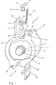
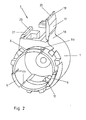
- 1 and 2 is a bearing plate to be fitted with metal brushes
- FIGS. 1 and 3 a bearing plate to be fitted with carbon brushes, each shown in a perspective view, FIGS. 1 and 3 showing the side facing away from the stator and FIGS. 2 and 4 showing the side facing the stator.
- FIG. 5 shows in section a bearing plate according to FIGS. 3 and 4, which is clipped into a plastic magnet.
- the one-piece bearing plate for metal brushes in Fig. 1 and 2 consists essentially of the base body 1, the compensating film 2, the bearing housing 3, the cylinder bearing 4, the thrust washer 5, the two receptacles 7 for the power transmission devices (metal brushes 13) and the two lids 17th
- the metal brush 13 here consists of a curved metal strip with a box-shaped carrier 15 and fingers 14. On the top and bottom of the carrier 15, an inwardly bent tab 16 is punched out, which are used to clamp a connecting wire. After the motor has been assembled, the brushes are inserted into the rectangular shaft 10, the fingers 14 resting against the collector of the rotor through the cutout 12. The underside of the carrier 15 of the brush 13 rests on the surface 8 of the rectangular shaft 10.
- the brush 13 When closing the lid 17, which is molded onto the base body 1 of the end shield by means of film hinges 18, the brush 13 is fixed to the collector. This is done on the one hand by the ramp-shaped elevation 9 on the support surface 8, on which the tab 16 of the underside of the carrier 15 rests, and on the other hand by the web 24, which is attached to the cover 17 and has a stiffening rib 25, which engages in the recess 12 and partially surrounds the carrier 15 of the brush 13, whereby the brush pressure on the collector is also exactly maintained.
- the cover 17 is provided at its front end with a nose 19 which, in the closed state, engages in the rear grip 22 of the holding device 21 attached to the base body 1.
- the snap-in is facilitated by the chamfer 20 on the nose 19 and by the chamfer 23 on the holding device 21.
- connecting webs 6a On the circumference of the base body 1 facing the stator, latching means are attached via connecting webs 6a, which in this case consist of three lugs 6 uniformly attached to the circumference of the base body. These locking lugs 6 snap directly into corresponding recesses 45 of an annular or ring-segment-shaped, injection-molded plastic magnet 41 during assembly of the motor (see also FIG. 5).
- the locking lugs 6 and the connecting webs 6a are each delimited by relief slots 6b, the clip properties being largely determined with the depth of the relief slots 6b.
- the shape of the locking lugs 6 and their connecting webs 6a to the base body 1 influence the locking.
- the bearing 4 can be designed as a cylindrical bearing and integrated into the bearing plate or into the bearing housing 3, that is to say together, as a result of the bearing plate clipped directly into the magnet be injected in one piece with the end shield.
- the thrust washer 5 for the shaft 44 of the rotor 42 is also integrated in the end shield.
- a piece 31 of a carbon guide 30 is used to receive the carbon brush 33.
- This shaft like the other parts of the end shield, is also made in one piece with the base body 1.
- the pressure spring 34 is inserted into the shaft 31 together with the coal 33 and then closed with the cover 17 as in FIGS. 1 and 2. Through the recesses 32, the (extended) end 35 of the spring 34 can be led out for power supply.
- the compensation film 2 is divided here for reasons of injection technology, but nevertheless fulfills the same task as in the aforementioned exemplary embodiment. Also resilient locking lugs 6 are provided for clipping in the magnet or the back of the motor.
Landscapes
- Engineering & Computer Science (AREA)
- Power Engineering (AREA)
- Physics & Mathematics (AREA)
- Electromagnetism (AREA)
- General Physics & Mathematics (AREA)
- Motor Or Generator Frames (AREA)
- Dc Machiner (AREA)
- Motor Or Generator Current Collectors (AREA)
Claims (9)
Priority Applications (1)
| Application Number | Priority Date | Filing Date | Title |
|---|---|---|---|
| AT85108429T ATE46232T1 (de) | 1984-07-16 | 1985-07-08 | Kommutatorseitiges lagerschild fuer gleichstromkleinstmotoren. |
Applications Claiming Priority (2)
| Application Number | Priority Date | Filing Date | Title |
|---|---|---|---|
| DE3426125A DE3426125C2 (de) | 1984-07-16 | 1984-07-16 | Kommutatorseitiger Lagerschild für Gleichstromkleinstmotoren |
| DE3426125 | 1984-07-16 |
Publications (3)
| Publication Number | Publication Date |
|---|---|
| EP0168742A2 EP0168742A2 (fr) | 1986-01-22 |
| EP0168742A3 EP0168742A3 (en) | 1987-04-29 |
| EP0168742B1 true EP0168742B1 (fr) | 1989-09-06 |
Family
ID=6240733
Family Applications (1)
| Application Number | Title | Priority Date | Filing Date |
|---|---|---|---|
| EP85108429A Expired EP0168742B1 (fr) | 1984-07-16 | 1985-07-08 | Flasque-palier du côté commutateur pour micromoteurs à courant continu |
Country Status (5)
| Country | Link |
|---|---|
| EP (1) | EP0168742B1 (fr) |
| JP (1) | JPS6139834A (fr) |
| KR (1) | KR860001512A (fr) |
| AT (1) | ATE46232T1 (fr) |
| DE (2) | DE3426125C2 (fr) |
Cited By (1)
| Publication number | Priority date | Publication date | Assignee | Title |
|---|---|---|---|---|
| WO2023193912A1 (fr) * | 2022-04-07 | 2023-10-12 | Pierburg Gmbh | Machine électrique |
Families Citing this family (3)
| Publication number | Priority date | Publication date | Assignee | Title |
|---|---|---|---|---|
| FR2684817A1 (fr) * | 1991-12-06 | 1993-06-11 | Valeo Systemes Dessuyage | Machine electrodynamique a circuit electrique de service integre. |
| DE19833802A1 (de) * | 1998-07-28 | 2000-02-03 | Bosch Gmbh Robert | Kommutator-Kleinmotor |
| CN115741567A (zh) * | 2022-11-09 | 2023-03-07 | 武义创锋工具制造有限公司 | 动力工具 |
Family Cites Families (6)
| Publication number | Priority date | Publication date | Assignee | Title |
|---|---|---|---|---|
| US2514693A (en) * | 1944-06-21 | 1950-07-11 | Garrett Corp | Motor assembly with magnetic brake |
| US3234417A (en) * | 1961-11-24 | 1966-02-08 | Sperry Rand Corp | Low voltage d.c. motor |
| DE1858063U (de) * | 1962-02-23 | 1962-09-06 | Diehl Fa | Buerstenhalter fuer gleichstrom-kleinmotoren. |
| US3339098A (en) * | 1965-03-02 | 1967-08-29 | Stanley Works | Commutator brush holder |
| DE2607103C3 (de) * | 1976-02-21 | 1978-08-03 | Gebr. Buehler Nachfolger Gmbh, 8500 Nuernberg | Kommutatorseitiges Lagerschild aus Kunststoff für Gleichstrom-Kleinstmotoren |
| US4355253A (en) * | 1981-02-27 | 1982-10-19 | Briggs & Stratton Corp. | Combination end bell and brush holder for a dynamoelectric machine |
-
1984
- 1984-07-16 DE DE3426125A patent/DE3426125C2/de not_active Expired
-
1985
- 1985-07-08 DE DE8585108429T patent/DE3572897D1/de not_active Expired
- 1985-07-08 EP EP85108429A patent/EP0168742B1/fr not_active Expired
- 1985-07-08 AT AT85108429T patent/ATE46232T1/de not_active IP Right Cessation
- 1985-07-15 KR KR1019850005030A patent/KR860001512A/ko not_active Withdrawn
- 1985-07-16 JP JP15532385A patent/JPS6139834A/ja active Pending
Cited By (1)
| Publication number | Priority date | Publication date | Assignee | Title |
|---|---|---|---|---|
| WO2023193912A1 (fr) * | 2022-04-07 | 2023-10-12 | Pierburg Gmbh | Machine électrique |
Also Published As
| Publication number | Publication date |
|---|---|
| DE3572897D1 (en) | 1989-10-12 |
| DE3426125C2 (de) | 1986-07-31 |
| EP0168742A3 (en) | 1987-04-29 |
| EP0168742A2 (fr) | 1986-01-22 |
| KR860001512A (ko) | 1986-02-26 |
| ATE46232T1 (de) | 1989-09-15 |
| DE3426125A1 (de) | 1986-01-23 |
| JPS6139834A (ja) | 1986-02-26 |
Similar Documents
| Publication | Publication Date | Title |
|---|---|---|
| DE68909458T2 (de) | Magnethalteanordnung für einen elektrischen Motor. | |
| EP1703620B1 (fr) | Entraînement électrique | |
| EP0538495A1 (fr) | Commande pour lève-glace de véhicule à moteur | |
| DE3629634C2 (fr) | ||
| WO2000036729A1 (fr) | Moteur a engrenage electrique pour groupes de vehicule | |
| DE10214926A1 (de) | Antriebsvorrichtung | |
| WO2008128838A1 (fr) | Moteur à courant continu comportant un condensateur de traversée | |
| DE19545651A1 (de) | Verstellvorrichtung für die Kohlebürsten an einem Elektromotor | |
| DE10130117A1 (de) | Gehäusedeckel für einen Elektromotor, insbesondere für einen elektronisch kommutierten Gleichstrommotor | |
| DE2813956B1 (de) | Kollektormotor mit einer in einer OEffnung des Motorgehaeuses fixierbaren Kunststoff-Buerstentragplatte | |
| EP0168742B1 (fr) | Flasque-palier du côté commutateur pour micromoteurs à courant continu | |
| WO2003067738A2 (fr) | Moteur electrique | |
| EP0168743B1 (fr) | Stator pour micromoteurs à courant continu | |
| EP1703617B1 (fr) | Entraînement électrique | |
| DE102013022020A1 (de) | Elektromotor, insbesondere Kühlerlüftermotor | |
| EP1797628B1 (fr) | Moteur electrique et unite d'entrainement electrique pour vehicules | |
| EP0556416B1 (fr) | Moteur à collecteur, en particulier pour une machine à laver et son procédé de fabrication | |
| EP0168744B1 (fr) | Flasque-palier pour micromoteurs à courant continu | |
| DE2230527A1 (de) | Geblaese mit einem elektromotor und einem von diesem angetriebenen luefterrad | |
| EP1416614A1 (fr) | Raccord adapter pour un moteur électrique | |
| EP0086386A1 (fr) | Dispositif de raccordement électrique pour un porte-balai électriquement conducteur, recevant un balai de carbone | |
| DE102008043569B4 (de) | Motorbaugruppe für Fensterheberanwendungen | |
| EP0467064B1 (fr) | Support de balais de charbon | |
| DE4327408C2 (de) | Elektromotor mit kleiner Leistung und Verfahren zu seiner Herstellung | |
| DE3842223A1 (de) | Elektromotor, insbesondere elektrischer kleinmotor |
Legal Events
| Date | Code | Title | Description |
|---|---|---|---|
| PUAI | Public reference made under article 153(3) epc to a published international application that has entered the european phase |
Free format text: ORIGINAL CODE: 0009012 |
|
| AK | Designated contracting states |
Designated state(s): AT DE FR GB NL |
|
| PUAL | Search report despatched |
Free format text: ORIGINAL CODE: 0009013 |
|
| AK | Designated contracting states |
Kind code of ref document: A3 Designated state(s): AT DE FR GB NL |
|
| 17P | Request for examination filed |
Effective date: 19870601 |
|
| 17Q | First examination report despatched |
Effective date: 19890201 |
|
| GRAA | (expected) grant |
Free format text: ORIGINAL CODE: 0009210 |
|
| AK | Designated contracting states |
Kind code of ref document: B1 Designated state(s): AT DE FR GB NL |
|
| REF | Corresponds to: |
Ref document number: 46232 Country of ref document: AT Date of ref document: 19890915 Kind code of ref document: T |
|
| REF | Corresponds to: |
Ref document number: 3572897 Country of ref document: DE Date of ref document: 19891012 |
|
| GBT | Gb: translation of ep patent filed (gb section 77(6)(a)/1977) | ||
| ET | Fr: translation filed | ||
| PGFP | Annual fee paid to national office [announced via postgrant information from national office to epo] |
Ref country code: GB Payment date: 19900627 Year of fee payment: 6 |
|
| PLBE | No opposition filed within time limit |
Free format text: ORIGINAL CODE: 0009261 |
|
| STAA | Information on the status of an ep patent application or granted ep patent |
Free format text: STATUS: NO OPPOSITION FILED WITHIN TIME LIMIT |
|
| PGFP | Annual fee paid to national office [announced via postgrant information from national office to epo] |
Ref country code: FR Payment date: 19900706 Year of fee payment: 6 |
|
| PGFP | Annual fee paid to national office [announced via postgrant information from national office to epo] |
Ref country code: AT Payment date: 19900711 Year of fee payment: 6 |
|
| PGFP | Annual fee paid to national office [announced via postgrant information from national office to epo] |
Ref country code: DE Payment date: 19900716 Year of fee payment: 6 |
|
| PGFP | Annual fee paid to national office [announced via postgrant information from national office to epo] |
Ref country code: NL Payment date: 19900731 Year of fee payment: 6 |
|
| 26N | No opposition filed | ||
| PG25 | Lapsed in a contracting state [announced via postgrant information from national office to epo] |
Ref country code: GB Effective date: 19910708 Ref country code: AT Effective date: 19910708 |
|
| PG25 | Lapsed in a contracting state [announced via postgrant information from national office to epo] |
Ref country code: NL Effective date: 19920201 |
|
| GBPC | Gb: european patent ceased through non-payment of renewal fee | ||
| NLV4 | Nl: lapsed or anulled due to non-payment of the annual fee | ||
| PG25 | Lapsed in a contracting state [announced via postgrant information from national office to epo] |
Ref country code: FR Effective date: 19920331 |
|
| PG25 | Lapsed in a contracting state [announced via postgrant information from national office to epo] |
Ref country code: DE Effective date: 19920401 |
|
| REG | Reference to a national code |
Ref country code: FR Ref legal event code: ST |