EP0168758A2 - Komprimiertrommel für Zigaretten - Google Patents
Komprimiertrommel für Zigaretten Download PDFInfo
- Publication number
- EP0168758A2 EP0168758A2 EP85108545A EP85108545A EP0168758A2 EP 0168758 A2 EP0168758 A2 EP 0168758A2 EP 85108545 A EP85108545 A EP 85108545A EP 85108545 A EP85108545 A EP 85108545A EP 0168758 A2 EP0168758 A2 EP 0168758A2
- Authority
- EP
- European Patent Office
- Prior art keywords
- compression
- sidewalls
- drum
- walls
- Prior art date
- Legal status (The legal status is an assumption and is not a legal conclusion. Google has not performed a legal analysis and makes no representation as to the accuracy of the status listed.)
- Withdrawn
Links
Images

Classifications
-
- B—PERFORMING OPERATIONS; TRANSPORTING
- B65—CONVEYING; PACKING; STORING; HANDLING THIN OR FILAMENTARY MATERIAL
- B65B—MACHINES, APPARATUS OR DEVICES FOR, OR METHODS OF, PACKAGING ARTICLES OR MATERIALS; UNPACKING
- B65B63/00—Auxiliary devices, not otherwise provided for, for operating on articles or materials to be packaged
- B65B63/02—Auxiliary devices, not otherwise provided for, for operating on articles or materials to be packaged for compressing or compacting articles or materials prior to wrapping or insertion in containers or receptacles
- B65B63/022—Auxiliary devices, not otherwise provided for, for operating on articles or materials to be packaged for compressing or compacting articles or materials prior to wrapping or insertion in containers or receptacles using compressing chambers or plates moving in an endless path
-
- B—PERFORMING OPERATIONS; TRANSPORTING
- B65—CONVEYING; PACKING; STORING; HANDLING THIN OR FILAMENTARY MATERIAL
- B65B—MACHINES, APPARATUS OR DEVICES FOR, OR METHODS OF, PACKAGING ARTICLES OR MATERIALS; UNPACKING
- B65B19/00—Packaging rod-shaped or tubular articles susceptible to damage by abrasion or pressure, e.g. cigarettes, cigars, macaroni, spaghetti, drinking straws or welding electrodes
- B65B19/02—Packaging cigarettes
- B65B19/04—Arranging, feeding, or orientating the cigarettes
- B65B19/10—Arranging cigarettes in layers each comprising a predetermined number
Definitions
- This invention relates to compression drums for orderly groups of cigarettes in automatic cigarette--packing machines, said compression drums comprising one or more tubular compression pockets each having a substantially rectangular cross-section and each including, at least partly, movable sidewalls permitting the cross-section of a pocket to be varied between a maximum expansion condition, wherein an orderly group of cigarettes to be packed is introduced thereinto, and a maximum compression condition, wherein the group of cigarettes received in the pocket is compressed.
- each compression pocket comprises two opposite L-shaped sections oppositely arranged to form the rectangular cross-section of the pocket and which are movable with respect to each other in a direction which is oblique to the sides of said cross-section, so as to mutually move toward each ,other and away from each other to achieve the maximum compression condition and the maximum expansion condition, respectively, of the pocket.
- each sidewall corresponding to a longer side of the rectangular cross-section of a pocket is integral with a sidewall corresponding to a shorter side of the rectangular cross-section of the pocket.
- the mutual displacement of the opposite sidewalls, corresponding to the longer sides of the cross-section of the pocket, and the mutual displacement of the opposite sidewalls, corresponding to the shorter sides of said cross-section depend both upon each other and upon the angle of the direction of the relative movement of the two L-shaped sections with respect to one of the sides, e.g. the longer side.
- This.dependence is a serious inconvenience, particularly when the cross-section of packages is to be changed.
- a change in the cross-section of a package of cigarettes may require a change in the angle of the direction of the relative movement of the two complementary L-shaped sections.
- This invention aims to avoid said drawbacks of the heretofore known devices, and it is substantially characterized in that at least two adjacent sidewalls of each compression pocket, one of which corresponds to a longer side and the other to a shorter side of the rectangular cross-section of a pocket, are separate from each other and from the other sidewalls of said pocket and are movable independently from each other, each one with respect to the respective opposite sidewall, so as to achieve a mutual movement of the walls of said pair of opposite sidewalls of a pocket toward and away from each other.
- the mutual displacement of the sidewalls corresponding to the longer sides of the rectangular cross-section of a pocket toward and away from each other while changing from the maximum expansion condition to the maximum compression condition, and vice versa is independent from the mutual movement of the two other sidewalls corresponding to the shorter sides of the cross-section of said pocket toward and away from each other.
- two adjacent sidewalls of a tubular compression pocket may be kept stationary in the compression drum, while the two other walls may be movably mounted in the compression drum independently from each other and substantially perpendicularly to the respective opposite stationary sidewalls.
- both walls of each pair of opposite sidewalls are mounted movably in a compression drum.
- any suitable actuating means may be used, preferably an actuating device having the characteristics set forth in the dependent claims.
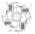
- 1 indicates the compression drum of an automatic cigarette-packing machine.
- a drum comprises, in a known manner, a ring of four tubular compression pockets 2 angularly equi-spaced from each other and arranged with the longitudinal axis of their interior parallel to the rotation axis of the drum 1.
- the compression drum 1 rotates intermittently, for example, in the direction of the arrow F, so as to make each pocket 2 stop, first at a loading station A whereat an orderly group of cigarettes G intended to for a package is axially introduced into a compression pocket 2, and then at a discharge station B whereat said group of cigarettes is axially ejected from the compression pocket 2 and is introduced into a tubular arbor whereon a single or a double wrapper for a package has been formed previously. While moving from the station A to the station B, the group of cigarettes G is compressed transversely to the cigarettes.
- the cross-section of the compression pocket 2 is reduced, said cross-section being in the maximum expansion condition at the station A, and a maximum compression condition at a station or position preceding the station B.
- the cross--section of the pocket 2 is again expanded slightly to facilitate the ejection of the compressed group of ,cigarettes G.
- Each compression pocket 2 has a rectangular cross--section and comprises two wider sidewalls 3 and 3', which are opposite and parallel to each other, and two narrower sidewalls 4 and 4', also opposite and parallel to each other.
- the sidewalls 3,3',4 and 4' are separate from each other and are movable independently from each other with respect to the compression drum 1 in order to change the cross-section of the respective compression pocket.
- each sidewall 3,3', 4,4' of each compression pocket 2 comprises - on the side opposite to the pocket interior-peripheral flanges 103, 103', 104, 104' and a central rib 203, 203', 204, 204', by means of which it is slidably guided, perpendicularly to its plane, in corresponding grooves in the body of the compression drum 1.
- the device for moving the two wider sidewalls 3, 3' and the two narrower sidewalls 4, 4' towards each other comprises two fixed cams 5 and 6 which are co-axial with the compression drum 1.
- Each compression pocket 2 has associated therewith two cam followers 7 and 8 which are radially slidably but not rotatably mounted within the body of the drum 1 in suitable guide sleeves 9 and which co-operate through end rollers 107, 108 one . (7) with the fixed cam (5) and the other (8) with the cam 6.
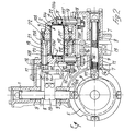
- the cam followers 7 and 8 are urged towards the respective cams 5 and 6 and are kept in contact therewith by means of associated springs 11, as shown in figure 2 in connection with the cam follower 7.
- the cam follower 7 controls the displacement of the narrower sidewalls 4, 4' of the associated pocket 2 and is located downstream thereof with respect to the direction of rotation F of the drum 1, whereas the cam follower 8 controls the displacement of the wider sidewalls 3, 3' of the associated pocket 2 and is located upstream of said pocket with respect to direction of rotation F of said drum 1, as clearly viewed in Figure 2.
- the two cam followers 7 and 8 are substantially perpendicular to each other and to the associated sidewalls 4, 4' and 3, 3' of the respective compression pocket 2.
- the displacing devices by means of which the cam followers 7 and 8 control the approaching and moving apart movements of the associated sidewalls 4, 4' and 3, 3' of the respective pocket 2, are identical for the two pairs of walls 4, 4' and 3, 3', i.e. for each cam follower 7 and 8. Therefore, we will describe bereinafter, with particular reference to Figure 3, only the displacing device associated with the cam follower 8 and arranged between said cam follower 8 and the pair of wider sidewalls 3, 3'.
- the cam follower 8 has fixed thereto a clamp 13 carrying two studs 14 engaged in a plate 15 which is substantially perpendicular to the two walls 3, 3' and movable in the plane thereof parallelly to the cam follower 8 in the body of the drum 1.
- the plate 15 mounts, for each wall 3, 3', two bushes 16, 16' which are slidable within corresponding slots 10 and 10' of said plate 15.
- Rotatably journaled in each of said bushes 16, 16' is a spindle 17, 17' which is connected by means of a crank 18, 18' to a corresponding excentric driving shaft 19, 19' which is rotatably but not axially slidably mounted in the body of the drum 1, e.g. in corresponding sleeves 20, 20' ( Figure 2).
- the driving shafts 19, 19', at the ends thereof remote from the cranks 18, 18', are provided each with a flange 21, 21' and an excentric pin 22, 22'.
- the excentric pins 22 of the two shafts 19 are engaged in slots 23 formed in the intermediate rear rib 203 of the wider sidewall 3 of the pocket 2, while the excentric pins 22' of the two other shafts 19' are engaged in similar slots 23' formed in the intermediate rear rib 203' of the other wider sidewall 3' of the pocket.
- the device for displacing the two other sidewalls 4, 4' of the compression pocket by means of the cam follower 7 has the same construction and operation of the one described above and can be viewed partly in Figure 2, in which figure the displacing device associated with the cam follower 7 and the narrower sidewalls 4, 4' of the pocket 2 have the same reference numerals that have been used for said displacing device associated with the cam follower 8 and wider sidewalls 3, 3' of the pocket.
- the cams 5 and 6 are contoured and are angularly adjusted so as to cause the mutual approaching, first of the wider walls 3, 3', and then of the narrower walls 4, 4'; however, a reversed sequence of the mutual approaching of the walls 3, 3' and 4, 4' or a simultaneous mutual approaching of all the walls 3,3', 4, 4' is possible.
- all the sidewalls 3, 3', 4, 4' of each compression pocket have planar and smooth inner surfaces.
- the narrower sidewalls 4, 4' may be provided, on the inner surface thereof, with a longitudinal rib in registry with the intermediate row of cigarettes, when the number of cigarettes in said intermediate row is smaller than the number of cigarettes in the outer rows.
Landscapes
- Engineering & Computer Science (AREA)
- Mechanical Engineering (AREA)
- Wrapping Of Specific Fragile Articles (AREA)
- Packaging Of Annular Or Rod-Shaped Articles, Wearing Apparel, Cassettes, Or The Like (AREA)
Applications Claiming Priority (2)
| Application Number | Priority Date | Filing Date | Title |
|---|---|---|---|
| IT12566/84A IT1180792B (it) | 1984-07-18 | 1984-07-18 | Tamburo compressore per gruppi ordinati di sigarette in macchine automatiche impacchettatrici di sigarette |
| IT1256684 | 1984-07-18 |
Publications (2)
| Publication Number | Publication Date |
|---|---|
| EP0168758A2 true EP0168758A2 (de) | 1986-01-22 |
| EP0168758A3 EP0168758A3 (de) | 1987-01-07 |
Family
ID=11141683
Family Applications (1)
| Application Number | Title | Priority Date | Filing Date |
|---|---|---|---|
| EP85108545A Withdrawn EP0168758A3 (de) | 1984-07-18 | 1985-07-09 | Komprimiertrommel für Zigaretten |
Country Status (4)
| Country | Link |
|---|---|
| US (1) | US4617783A (de) |
| EP (1) | EP0168758A3 (de) |
| JP (1) | JPS6133911A (de) |
| IT (1) | IT1180792B (de) |
Cited By (2)
| Publication number | Priority date | Publication date | Assignee | Title |
|---|---|---|---|---|
| EP0689995A1 (de) * | 1994-06-30 | 1996-01-03 | G.D Societa' Per Azioni | Vorrichtung zum Zuführen von Gruppen von Tabakartikeln zu einer Umwickelstrasse |
| EP0706943A1 (de) * | 1994-10-14 | 1996-04-17 | Maschinenfabrik Alfred Schmermund GmbH & Co. | Förderer zum Zusammenpressen von Zigarettenblöcken |
Families Citing this family (3)
| Publication number | Priority date | Publication date | Assignee | Title |
|---|---|---|---|---|
| SE464353B (sv) * | 1988-07-20 | 1991-04-15 | Vmk Fish Machinery Ab | Maskin foer placering av fiskar i konservburk |
| DE3935971A1 (de) * | 1989-10-28 | 1991-05-02 | Schmermund Maschf Alfred | Vorrichtung zum bilden von zigarettengruppen |
| CN111532497B (zh) * | 2020-05-07 | 2021-07-09 | 杭州逸飞橡塑有限公司 | 一种橡胶制造自动化加工处理系统 |
Family Cites Families (9)
| Publication number | Priority date | Publication date | Assignee | Title |
|---|---|---|---|---|
| GB260150A (en) * | 1926-03-10 | 1926-10-28 | Johann Carl Muller | Improvements in machines for transferring cigarettes from a supply hopper into packets |
| US2209110A (en) * | 1937-10-29 | 1940-07-23 | Molins Machine Co Ltd | Wrapping machine |
| GB495296A (en) * | 1937-10-29 | 1938-11-10 | John Walker Chalmers | Improvements in or relating to cigarette packing or wrapping machines |
| US3186140A (en) * | 1962-02-23 | 1965-06-01 | Joseph M Bogdanovich | Packing machines |
| DE1182581B (de) * | 1962-11-29 | 1964-11-26 | Holstein & Kappert Maschf | Verfahren und Vorrichtung zur Herstellung von Quaderpackungen |
| GB1203223A (en) * | 1966-09-19 | 1970-08-26 | Hauni Werke Koerber & Co Kg | Method and machine for packaging or wrapping block-shaped articles |
| US3590556A (en) * | 1968-01-05 | 1971-07-06 | Heinz Focke | Machine for packing of cigarettes in soft packets |
| US3583130A (en) * | 1969-05-27 | 1971-06-08 | Amf Inc | Cigarette packers |
| US4341056A (en) * | 1980-03-17 | 1982-07-27 | Magna-Graphics Corporation | Machine for compression band packaging |
-
1984
- 1984-07-18 IT IT12566/84A patent/IT1180792B/it active
-
1985
- 1985-07-09 EP EP85108545A patent/EP0168758A3/de not_active Withdrawn
- 1985-07-11 US US06/754,451 patent/US4617783A/en not_active Expired - Fee Related
- 1985-07-18 JP JP15921485A patent/JPS6133911A/ja active Pending
Cited By (3)
| Publication number | Priority date | Publication date | Assignee | Title |
|---|---|---|---|---|
| EP0689995A1 (de) * | 1994-06-30 | 1996-01-03 | G.D Societa' Per Azioni | Vorrichtung zum Zuführen von Gruppen von Tabakartikeln zu einer Umwickelstrasse |
| EP0706943A1 (de) * | 1994-10-14 | 1996-04-17 | Maschinenfabrik Alfred Schmermund GmbH & Co. | Förderer zum Zusammenpressen von Zigarettenblöcken |
| US5649615A (en) * | 1994-10-14 | 1997-07-22 | Maschinenfabrik Alfred Schmermund Gmbh & Co. | Conveyor for compressing cigarette blocks |
Also Published As
| Publication number | Publication date |
|---|---|
| US4617783A (en) | 1986-10-21 |
| EP0168758A3 (de) | 1987-01-07 |
| IT8412566A0 (it) | 1984-07-18 |
| JPS6133911A (ja) | 1986-02-18 |
| IT1180792B (it) | 1987-09-23 |
Similar Documents
| Publication | Publication Date | Title |
|---|---|---|
| US4823536A (en) | Handling method and device | |
| US5927473A (en) | Product conveying device | |
| CA1213295A (en) | Paper sheet collecting apparatus | |
| US4995223A (en) | Continuous wrapping machine | |
| CN1006153B (zh) | 分组传送卷烟的设备 | |
| GB2141990A (en) | Apparatus for transferring product to selected paths | |
| CN1006154B (zh) | 用至少一种可折叠坯料制造(香烟)包装件的装置 | |
| CS252812B2 (en) | Equipment for cigarette semi-products'axial shifting | |
| US4125184A (en) | Switching device for switching a cigarette flow | |
| US4617783A (en) | Compression drum for cigarettes | |
| CN106392729B (zh) | 链式仓、机床和应用 | |
| KR20180083851A (ko) | 담배 산업의 로드형 제품들의 중앙 정렬 장치 | |
| PL233095B1 (pl) | Sposób przesuwania artykułów prętopodobnych, oraz urządzenie do przesuwania artykułów prętopodobnych | |
| EP0792806B1 (de) | Vorrichtung zum Fördern von Paketen | |
| EP1138215B1 (de) | Trenntrommel zum axialen Positionieren von zwei koaxialen Zigarettenportionen in einer Filteransetzmaschine | |
| EP0509293B1 (de) | Vorrichtung zum Überführen und Verpacken | |
| EP0792810A1 (de) | Ausgangseinheit für kontinuierliche Wickelmaschine | |
| US5769205A (en) | Continuous cigarette manufacturing machine | |
| US4531627A (en) | Device for forming groups of cigarettes in cigarette packaging machines | |
| EP1319597B1 (de) | Verfahren und Vorrichtung zum Übertragen von Verpackungen | |
| EP0790186A1 (de) | Anlage zum Formen von Zigarettengruppen | |
| RU2226487C2 (ru) | Способ передачи изделий | |
| US6006492A (en) | Machine for packing groups of cigarettes | |
| US4685554A (en) | Ejection method and apparatus | |
| US4631904A (en) | Apparatus for compressing cigarettes |
Legal Events
| Date | Code | Title | Description |
|---|---|---|---|
| PUAI | Public reference made under article 153(3) epc to a published international application that has entered the european phase |
Free format text: ORIGINAL CODE: 0009012 |
|
| AK | Designated contracting states |
Designated state(s): CH DE FR GB LI NL SE |
|
| PUAL | Search report despatched |
Free format text: ORIGINAL CODE: 0009013 |
|
| AK | Designated contracting states |
Kind code of ref document: A3 Designated state(s): CH DE FR GB LI NL SE |
|
| STAA | Information on the status of an ep patent application or granted ep patent |
Free format text: STATUS: THE APPLICATION IS DEEMED TO BE WITHDRAWN |
|
| 18D | Application deemed to be withdrawn |
Effective date: 19870708 |
|
| RIN1 | Information on inventor provided before grant (corrected) |
Inventor name: MANSERVISI, RENATO |