EP0168935B1 - Dispositif pour transporter des objets coniques - Google Patents
Dispositif pour transporter des objets coniques Download PDFInfo
- Publication number
- EP0168935B1 EP0168935B1 EP85303960A EP85303960A EP0168935B1 EP 0168935 B1 EP0168935 B1 EP 0168935B1 EP 85303960 A EP85303960 A EP 85303960A EP 85303960 A EP85303960 A EP 85303960A EP 0168935 B1 EP0168935 B1 EP 0168935B1
- Authority
- EP
- European Patent Office
- Prior art keywords
- chute
- conical
- tubes
- conveyor
- along
- Prior art date
- Legal status (The legal status is an assumption and is not a legal conclusion. Google has not performed a legal analysis and makes no representation as to the accuracy of the status listed.)
- Expired
Links
Images
Classifications
-
- B—PERFORMING OPERATIONS; TRANSPORTING
- B65—CONVEYING; PACKING; STORING; HANDLING THIN OR FILAMENTARY MATERIAL
- B65G—TRANSPORT OR STORAGE DEVICES, e.g. CONVEYORS FOR LOADING OR TIPPING, SHOP CONVEYOR SYSTEMS OR PNEUMATIC TUBE CONVEYORS
- B65G15/00—Conveyors having endless load-conveying surfaces, i.e. belts and like continuous members, to which tractive effort is transmitted by means other than endless driving elements of similar configuration
- B65G15/10—Conveyors having endless load-conveying surfaces, i.e. belts and like continuous members, to which tractive effort is transmitted by means other than endless driving elements of similar configuration comprising two or more co-operating endless surfaces with parallel longitudinal axes, or a multiplicity of parallel elements, e.g. ropes defining an endless surface
- B65G15/12—Conveyors having endless load-conveying surfaces, i.e. belts and like continuous members, to which tractive effort is transmitted by means other than endless driving elements of similar configuration comprising two or more co-operating endless surfaces with parallel longitudinal axes, or a multiplicity of parallel elements, e.g. ropes defining an endless surface with two or more endless belts
-
- B—PERFORMING OPERATIONS; TRANSPORTING
- B65—CONVEYING; PACKING; STORING; HANDLING THIN OR FILAMENTARY MATERIAL
- B65H—HANDLING THIN OR FILAMENTARY MATERIAL, e.g. SHEETS, WEBS, CABLES
- B65H67/00—Replacing or removing cores, receptacles, or completed packages at paying-out, winding, or depositing stations
- B65H67/06—Supplying cores, receptacles, or packages to, or transporting from, winding or depositing stations
- B65H67/068—Supplying or transporting empty cores
-
- B—PERFORMING OPERATIONS; TRANSPORTING
- B65—CONVEYING; PACKING; STORING; HANDLING THIN OR FILAMENTARY MATERIAL
- B65G—TRANSPORT OR STORAGE DEVICES, e.g. CONVEYORS FOR LOADING OR TIPPING, SHOP CONVEYOR SYSTEMS OR PNEUMATIC TUBE CONVEYORS
- B65G2201/00—Indexing codes relating to handling devices, e.g. conveyors, characterised by the type of product or load being conveyed or handled
- B65G2201/02—Articles
-
- B—PERFORMING OPERATIONS; TRANSPORTING
- B65—CONVEYING; PACKING; STORING; HANDLING THIN OR FILAMENTARY MATERIAL
- B65H—HANDLING THIN OR FILAMENTARY MATERIAL, e.g. SHEETS, WEBS, CABLES
- B65H2701/00—Handled material; Storage means
- B65H2701/30—Handled filamentary material
- B65H2701/31—Textiles threads or artificial strands of filaments
Definitions
- the present invention relates to textile apparatus having a conveyor for transporting conical objects, such as conical winding tubes for conical yarn packages, to a point of use.
- US-A-3082908 discloses an inclined delivery chute for conical winding tubes such that the chute is arcuate to allow the winding tubes to roll down the inclined plane while following an arcuate path in which their rotation axes rotate about an axis perpendicular to the plane of the chute flow.
- the tubes follow the curved path because they all have the same orientation, i.e. their wider ends are at the same side of the chute. Without the curvature of the path the bobbins would fail to rotate but would jam.
- the present invention is characterised in that the conveyor comprises: an inclined chute for transporting a succession of the conical tubes between the receiving end and the delivery end of the chute with alternating orientation of successive tubes along the chute; support means extending along the chute to maintain the axis of symmetry of each conical tube substantially parallel to the chute floor; and first and second means laterally spaced with respect to the chute centre line on respective opposite sides thereof and moving along the chute in a direction from the delivery end to the receiving end thereof, each having a friction surface to engage and to swivel the conical tubes on the chute for rotating such tubes to cause them to realign their axes to remain mutually parallel as they roll along the chute.
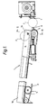
- Figures 1 and 2 show a tube transport conveyor 1 which receives empty winding cores at the receiving end 1a and transports them along a shallowly downwardly inclined path towards the deliver end 1b of the transport conveyor.
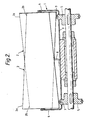
- the tubes 2 are conical and need to be arranged in alternating orientation so that the centre lines of the tubes are substantially parallel to one another; in other words the narrow end 2b of every other tube 2 will be to one side of the conveyor 1 and the narrow end 2b of each intervening tube is to the opposite side as shown in Figure 2. Since conical tubes will not roll in a straight line, it will be necessary to swivel the tubes to maintain their axes of rotation mutually parallel so they do not jam-up against the side walls of the conveyor and preferably this is achieved by virtue of two endless bands 3 which are each arranged adjacent to a respective side wall 4 of the tube transport chute and consequently engage frictionally with the larger diameter ends 2a of conical tubes passing along the chute.
- the endless bands 3 are supported on pulleys 5 and are driven for circulation in a direction such that the upper run moves countercurrent to the direction of movement of yarn winding tubes from the receiving end 1a to the delivery end 1b of the transport conveyor, and this causes the tubes 2 to swivel in the appropriate direction.
- Inversion of a tube is carried out by extending the holding pin 6 into the position shown in Figure 2 where it holds a tube 2 against the rotatable shoe 7.
- the axes of the empty tubes 2 are kept parallel to one another and to the floor 9 of the chute by means of a central longitudinal fin 8 upstanding from the floor of the chute and supporting each tube 2 midway along its length.
- the conveyor described above may, for example, be incorporated in a doffer robot for an open end spinning machine.
- conveyors may be used for transporting any conical abject and not merely empty winding tubes for spinning machines.
Landscapes
- Engineering & Computer Science (AREA)
- Mechanical Engineering (AREA)
- Replacing, Conveying, And Pick-Finding For Filamentary Materials (AREA)
- Spinning Or Twisting Of Yarns (AREA)
Claims (6)
Applications Claiming Priority (2)
| Application Number | Priority Date | Filing Date | Title |
|---|---|---|---|
| GB08415002A GB2160181B (en) | 1984-06-13 | 1984-06-13 | Conveyor for conical objects |
| GB8415002 | 1984-06-13 |
Publications (2)
| Publication Number | Publication Date |
|---|---|
| EP0168935A1 EP0168935A1 (fr) | 1986-01-22 |
| EP0168935B1 true EP0168935B1 (fr) | 1987-08-12 |
Family
ID=10562337
Family Applications (1)
| Application Number | Title | Priority Date | Filing Date |
|---|---|---|---|
| EP85303960A Expired EP0168935B1 (fr) | 1984-06-13 | 1985-06-04 | Dispositif pour transporter des objets coniques |
Country Status (4)
| Country | Link |
|---|---|
| US (1) | US4648502A (fr) |
| EP (1) | EP0168935B1 (fr) |
| DE (1) | DE3560442D1 (fr) |
| GB (1) | GB2160181B (fr) |
Cited By (1)
| Publication number | Priority date | Publication date | Assignee | Title |
|---|---|---|---|---|
| DE3939594A1 (de) * | 1989-11-30 | 1991-06-06 | Palitex Project Co Gmbh | Huelsenmagazin fuer spulenhuelsen |
Families Citing this family (2)
| Publication number | Priority date | Publication date | Assignee | Title |
|---|---|---|---|---|
| GB2190664A (en) * | 1986-05-23 | 1987-11-25 | Hollingsworth | Apparatus for dispensing a succession of conical objects |
| US6478139B1 (en) * | 1999-10-28 | 2002-11-12 | Norse Dairy Systems, Inc. | Conveyor and packaging apparatus and packaging conveyance and packaging methods |
Family Cites Families (9)
| Publication number | Priority date | Publication date | Assignee | Title |
|---|---|---|---|---|
| GB258966A (fr) * | ||||
| US3031059A (en) * | 1958-10-13 | 1962-04-24 | Deering Milliken Res Corp | Bobbin handling apparatus |
| US3082908A (en) * | 1958-10-13 | 1963-03-26 | Deering Milliken Res Corp | Bobbin handling arrangement |
| US3117663A (en) * | 1963-03-14 | 1964-01-14 | Cavalier Corp | Shelf assembly for vending machines |
| US3298166A (en) * | 1964-02-11 | 1967-01-17 | Draper Corp | Bobbin guiding grate |
| US3302452A (en) * | 1964-04-27 | 1967-02-07 | Cutler Hammer Inc | Coagulation detector and coagulability determination |
| US3276565A (en) * | 1965-01-11 | 1966-10-04 | Rockford Screw Products Co | Automatic orienting mechanism |
| US3328948A (en) * | 1965-04-02 | 1967-07-04 | Willcox & Gibbs Sewing Machine | Donning device and article handling means therefor |
| CH631414A5 (de) * | 1978-06-06 | 1982-08-13 | Rieter Ag Maschf | Vorrichtung zum endengleichen sortieren von konischen huelsen fuer textilmaschinen. |
-
1984
- 1984-06-13 GB GB08415002A patent/GB2160181B/en not_active Expired
-
1985
- 1985-06-04 DE DE8585303960T patent/DE3560442D1/de not_active Expired
- 1985-06-04 EP EP85303960A patent/EP0168935B1/fr not_active Expired
- 1985-06-11 US US06/743,538 patent/US4648502A/en not_active Expired - Fee Related
Cited By (1)
| Publication number | Priority date | Publication date | Assignee | Title |
|---|---|---|---|---|
| DE3939594A1 (de) * | 1989-11-30 | 1991-06-06 | Palitex Project Co Gmbh | Huelsenmagazin fuer spulenhuelsen |
Also Published As
| Publication number | Publication date |
|---|---|
| GB8415002D0 (en) | 1984-07-18 |
| DE3560442D1 (en) | 1987-09-17 |
| US4648502A (en) | 1987-03-10 |
| GB2160181B (en) | 1987-08-19 |
| GB2160181A (en) | 1985-12-18 |
| EP0168935A1 (fr) | 1986-01-22 |
Similar Documents
| Publication | Publication Date | Title |
|---|---|---|
| EP0061432A1 (fr) | Dispositif pour le transport de bobines | |
| JP3113597B2 (ja) | 物品を単一縦列に整える搬送機構 | |
| US3788054A (en) | Apparatus for transporting and storing yarn pirns or the like | |
| EP1161392B1 (fr) | Procedes et appareil permettant d'acheminer des paquets avec un minimum de blocages | |
| US3835985A (en) | Vacuum assist can unscrambler | |
| JPS6326041B2 (fr) | ||
| CN1070140C (zh) | 垂向输送卷烟盒的方法和装置 | |
| US4295569A (en) | Apparatus for sorting textile bobbins | |
| US3734264A (en) | Conveyor-magazine adapted for being interposed between a folding machine and stations where subsequent operations are effected | |
| US5078329A (en) | Package delivery arrangement for automatic yarn winding apparatus | |
| GB2122159A (en) | Feeding apparatus particularly for machines for the conveyance and sorting of objects | |
| EP0168935A1 (fr) | Dispositif pour transporter des objets coniques | |
| US5839569A (en) | Method of conveying tubes on a textile machine and device for carrying out the method | |
| US5176245A (en) | Conveyor device for transporting peg trays | |
| US6029800A (en) | Conveyor for articles with wave-shaped rollers | |
| US5179829A (en) | Combined textile yarn spinning and winding system having spinning tube transporting means | |
| US3746212A (en) | Device for isolating textile coils | |
| JPS60217926A (ja) | 高速製造機において衛生用品を製造するための方法及び装置 | |
| US5168696A (en) | Arrangement for conveying packages away from a spinning machine | |
| US4846414A (en) | Method and apparatus for automatic orderly removal and collection of fully-spun cops from textile ring spinning machines | |
| JPH04226277A (ja) | より合わせ機械 | |
| GB2315476A (en) | Yarn package transport system | |
| US4564147A (en) | Winding machine | |
| US5184785A (en) | Double-sided textile machine having a plurality of winding units for producing cross-wound packages | |
| US4705266A (en) | Sheet convey device |
Legal Events
| Date | Code | Title | Description |
|---|---|---|---|
| PUAI | Public reference made under article 153(3) epc to a published international application that has entered the european phase |
Free format text: ORIGINAL CODE: 0009012 |
|
| 17P | Request for examination filed |
Effective date: 19851112 |
|
| AK | Designated contracting states |
Designated state(s): CH DE FR GB IT LI |
|
| 17Q | First examination report despatched |
Effective date: 19860707 |
|
| GRAA | (expected) grant |
Free format text: ORIGINAL CODE: 0009210 |
|
| AK | Designated contracting states |
Kind code of ref document: B1 Designated state(s): CH DE FR IT LI |
|
| REF | Corresponds to: |
Ref document number: 3560442 Country of ref document: DE Date of ref document: 19870917 |
|
| ITF | It: translation for a ep patent filed | ||
| ET | Fr: translation filed | ||
| PLBE | No opposition filed within time limit |
Free format text: ORIGINAL CODE: 0009261 |
|
| STAA | Information on the status of an ep patent application or granted ep patent |
Free format text: STATUS: NO OPPOSITION FILED WITHIN TIME LIMIT |
|
| 26N | No opposition filed | ||
| PGFP | Annual fee paid to national office [announced via postgrant information from national office to epo] |
Ref country code: FR Payment date: 19920513 Year of fee payment: 8 |
|
| PGFP | Annual fee paid to national office [announced via postgrant information from national office to epo] |
Ref country code: DE Payment date: 19920521 Year of fee payment: 8 Ref country code: CH Payment date: 19920521 Year of fee payment: 8 |
|
| ITTA | It: last paid annual fee | ||
| PG25 | Lapsed in a contracting state [announced via postgrant information from national office to epo] |
Ref country code: LI Effective date: 19930630 Ref country code: CH Effective date: 19930630 |
|
| PG25 | Lapsed in a contracting state [announced via postgrant information from national office to epo] |
Ref country code: FR Effective date: 19940228 |
|
| REG | Reference to a national code |
Ref country code: CH Ref legal event code: PL |
|
| PG25 | Lapsed in a contracting state [announced via postgrant information from national office to epo] |
Ref country code: DE Effective date: 19940301 |
|
| REG | Reference to a national code |
Ref country code: FR Ref legal event code: ST |