EP0168953B2 - Stab aus Verbundmaterialien und Verfahren zu seiner Herstellung - Google Patents
Stab aus Verbundmaterialien und Verfahren zu seiner Herstellung Download PDFInfo
- Publication number
- EP0168953B2 EP0168953B2 EP85304135A EP85304135A EP0168953B2 EP 0168953 B2 EP0168953 B2 EP 0168953B2 EP 85304135 A EP85304135 A EP 85304135A EP 85304135 A EP85304135 A EP 85304135A EP 0168953 B2 EP0168953 B2 EP 0168953B2
- Authority
- EP
- European Patent Office
- Prior art keywords
- hot
- stick
- pressed
- hard
- head member
- Prior art date
- Legal status (The legal status is an assumption and is not a legal conclusion. Google has not performed a legal analysis and makes no representation as to the accuracy of the status listed.)
- Expired - Lifetime
Links
- 239000002131 composite material Substances 0.000 title claims description 79
- 238000000034 method Methods 0.000 title claims description 38
- 238000002360 preparation method Methods 0.000 title description 2
- 239000010410 layer Substances 0.000 claims description 72
- 239000000956 alloy Substances 0.000 claims description 55
- 229910045601 alloy Inorganic materials 0.000 claims description 55
- 239000000843 powder Substances 0.000 claims description 50
- 229910003460 diamond Inorganic materials 0.000 claims description 44
- 239000010432 diamond Substances 0.000 claims description 44
- 239000002245 particle Substances 0.000 claims description 28
- 238000005520 cutting process Methods 0.000 claims description 26
- 229910052582 BN Inorganic materials 0.000 claims description 22
- 239000000463 material Substances 0.000 claims description 22
- PZNSFCLAULLKQX-UHFFFAOYSA-N Boron nitride Chemical compound N#B PZNSFCLAULLKQX-UHFFFAOYSA-N 0.000 claims description 21
- 239000011230 binding agent Substances 0.000 claims description 16
- 239000011229 interlayer Substances 0.000 claims description 13
- 238000003825 pressing Methods 0.000 claims description 12
- XEEYBQQBJWHFJM-UHFFFAOYSA-N Iron Chemical group [Fe] XEEYBQQBJWHFJM-UHFFFAOYSA-N 0.000 claims description 9
- 238000007731 hot pressing Methods 0.000 claims description 8
- 229910052751 metal Inorganic materials 0.000 claims description 8
- 239000002184 metal Substances 0.000 claims description 8
- UONOETXJSWQNOL-UHFFFAOYSA-N tungsten carbide Chemical compound [W+]#[C-] UONOETXJSWQNOL-UHFFFAOYSA-N 0.000 claims description 8
- 238000004519 manufacturing process Methods 0.000 claims description 7
- 239000000203 mixture Substances 0.000 description 19
- 229910009043 WC-Co Inorganic materials 0.000 description 17
- 239000013078 crystal Substances 0.000 description 11
- 238000003754 machining Methods 0.000 description 11
- 239000012071 phase Substances 0.000 description 11
- 238000005452 bending Methods 0.000 description 8
- 238000000227 grinding Methods 0.000 description 8
- 229910000831 Steel Inorganic materials 0.000 description 6
- 239000011796 hollow space material Substances 0.000 description 6
- 239000010959 steel Substances 0.000 description 6
- 239000004593 Epoxy Substances 0.000 description 5
- 238000001816 cooling Methods 0.000 description 5
- 238000002474 experimental method Methods 0.000 description 5
- 230000005496 eutectics Effects 0.000 description 4
- 229910052759 nickel Inorganic materials 0.000 description 4
- 239000012466 permeate Substances 0.000 description 4
- 238000005245 sintering Methods 0.000 description 4
- 239000000126 substance Substances 0.000 description 4
- 230000004323 axial length Effects 0.000 description 3
- 238000010894 electron beam technology Methods 0.000 description 3
- 230000010354 integration Effects 0.000 description 3
- 239000007788 liquid Substances 0.000 description 3
- 238000003466 welding Methods 0.000 description 3
- 229920001342 Bakelite® Polymers 0.000 description 2
- 230000002159 abnormal effect Effects 0.000 description 2
- 238000005299 abrasion Methods 0.000 description 2
- 238000005219 brazing Methods 0.000 description 2
- 230000007547 defect Effects 0.000 description 2
- 238000005553 drilling Methods 0.000 description 2
- 239000003365 glass fiber Substances 0.000 description 2
- 238000010438 heat treatment Methods 0.000 description 2
- 229910052742 iron Inorganic materials 0.000 description 2
- 150000004767 nitrides Chemical class 0.000 description 2
- 238000004080 punching Methods 0.000 description 2
- 239000007787 solid Substances 0.000 description 2
- 239000000243 solution Substances 0.000 description 2
- 229910000531 Co alloy Inorganic materials 0.000 description 1
- BQCADISMDOOEFD-UHFFFAOYSA-N Silver Chemical compound [Ag] BQCADISMDOOEFD-UHFFFAOYSA-N 0.000 description 1
- ATJFFYVFTNAWJD-UHFFFAOYSA-N Tin Chemical compound [Sn] ATJFFYVFTNAWJD-UHFFFAOYSA-N 0.000 description 1
- 229910001080 W alloy Inorganic materials 0.000 description 1
- 238000010420 art technique Methods 0.000 description 1
- 239000004637 bakelite Substances 0.000 description 1
- 239000011195 cermet Substances 0.000 description 1
- 239000000470 constituent Substances 0.000 description 1
- 230000008021 deposition Effects 0.000 description 1
- 230000018109 developmental process Effects 0.000 description 1
- 238000009792 diffusion process Methods 0.000 description 1
- 239000003822 epoxy resin Substances 0.000 description 1
- 229910052735 hafnium Inorganic materials 0.000 description 1
- 230000002706 hydrostatic effect Effects 0.000 description 1
- 230000001788 irregular Effects 0.000 description 1
- 150000001247 metal acetylides Chemical class 0.000 description 1
- 239000007769 metal material Substances 0.000 description 1
- 238000002156 mixing Methods 0.000 description 1
- 229910052750 molybdenum Inorganic materials 0.000 description 1
- 230000000737 periodic effect Effects 0.000 description 1
- 230000000704 physical effect Effects 0.000 description 1
- 229920000647 polyepoxide Polymers 0.000 description 1
- 238000007670 refining Methods 0.000 description 1
- 229920005989 resin Polymers 0.000 description 1
- 239000011347 resin Substances 0.000 description 1
- 230000000452 restraining effect Effects 0.000 description 1
- 229910052709 silver Inorganic materials 0.000 description 1
- 239000004332 silver Substances 0.000 description 1
- 239000007779 soft material Substances 0.000 description 1
- 239000007790 solid phase Substances 0.000 description 1
- 239000006104 solid solution Substances 0.000 description 1
- 239000002904 solvent Substances 0.000 description 1
- 239000007858 starting material Substances 0.000 description 1
- 239000002344 surface layer Substances 0.000 description 1
- 229910052719 titanium Inorganic materials 0.000 description 1
- 229910003470 tongbaite Inorganic materials 0.000 description 1
- 229910052721 tungsten Inorganic materials 0.000 description 1
- 229910052984 zinc sulfide Inorganic materials 0.000 description 1
- 229910052726 zirconium Inorganic materials 0.000 description 1
Images

Classifications
-
- B—PERFORMING OPERATIONS; TRANSPORTING
- B23—MACHINE TOOLS; METAL-WORKING NOT OTHERWISE PROVIDED FOR
- B23P—METAL-WORKING NOT OTHERWISE PROVIDED FOR; COMBINED OPERATIONS; UNIVERSAL MACHINE TOOLS
- B23P5/00—Setting gems or the like on metal parts, e.g. diamonds on tools
-
- B—PERFORMING OPERATIONS; TRANSPORTING
- B22—CASTING; POWDER METALLURGY
- B22F—WORKING METALLIC POWDER; MANUFACTURE OF ARTICLES FROM METALLIC POWDER; MAKING METALLIC POWDER; APPARATUS OR DEVICES SPECIALLY ADAPTED FOR METALLIC POWDER
- B22F7/00—Manufacture of composite layers, workpieces, or articles, comprising metallic powder, by sintering the powder, with or without compacting wherein at least one part is obtained by sintering or compression
- B22F7/06—Manufacture of composite layers, workpieces, or articles, comprising metallic powder, by sintering the powder, with or without compacting wherein at least one part is obtained by sintering or compression of composite workpieces or articles from parts, e.g. to form tipped tools
-
- B—PERFORMING OPERATIONS; TRANSPORTING
- B23—MACHINE TOOLS; METAL-WORKING NOT OTHERWISE PROVIDED FOR
- B23B—TURNING; BORING
- B23B51/00—Tools for drilling machines
- B23B51/02—Twist drills
-
- B—PERFORMING OPERATIONS; TRANSPORTING
- B23—MACHINE TOOLS; METAL-WORKING NOT OTHERWISE PROVIDED FOR
- B23B—TURNING; BORING
- B23B51/00—Tools for drilling machines
- B23B51/011—Micro drills
-
- Y—GENERAL TAGGING OF NEW TECHNOLOGICAL DEVELOPMENTS; GENERAL TAGGING OF CROSS-SECTIONAL TECHNOLOGIES SPANNING OVER SEVERAL SECTIONS OF THE IPC; TECHNICAL SUBJECTS COVERED BY FORMER USPC CROSS-REFERENCE ART COLLECTIONS [XRACs] AND DIGESTS
- Y10—TECHNICAL SUBJECTS COVERED BY FORMER USPC
- Y10T—TECHNICAL SUBJECTS COVERED BY FORMER US CLASSIFICATION
- Y10T408/00—Cutting by use of rotating axially moving tool
- Y10T408/78—Tool of specific diverse material
-
- Y—GENERAL TAGGING OF NEW TECHNOLOGICAL DEVELOPMENTS; GENERAL TAGGING OF CROSS-SECTIONAL TECHNOLOGIES SPANNING OVER SEVERAL SECTIONS OF THE IPC; TECHNICAL SUBJECTS COVERED BY FORMER USPC CROSS-REFERENCE ART COLLECTIONS [XRACs] AND DIGESTS
- Y10—TECHNICAL SUBJECTS COVERED BY FORMER USPC
- Y10T—TECHNICAL SUBJECTS COVERED BY FORMER US CLASSIFICATION
- Y10T428/00—Stock material or miscellaneous articles
- Y10T428/12—All metal or with adjacent metals
- Y10T428/12014—All metal or with adjacent metals having metal particles
- Y10T428/12028—Composite; i.e., plural, adjacent, spatially distinct metal components [e.g., layers, etc.]
- Y10T428/12049—Nonmetal component
- Y10T428/12056—Entirely inorganic
-
- Y—GENERAL TAGGING OF NEW TECHNOLOGICAL DEVELOPMENTS; GENERAL TAGGING OF CROSS-SECTIONAL TECHNOLOGIES SPANNING OVER SEVERAL SECTIONS OF THE IPC; TECHNICAL SUBJECTS COVERED BY FORMER USPC CROSS-REFERENCE ART COLLECTIONS [XRACs] AND DIGESTS
- Y10—TECHNICAL SUBJECTS COVERED BY FORMER USPC
- Y10T—TECHNICAL SUBJECTS COVERED BY FORMER US CLASSIFICATION
- Y10T428/00—Stock material or miscellaneous articles
- Y10T428/12—All metal or with adjacent metals
- Y10T428/12014—All metal or with adjacent metals having metal particles
- Y10T428/12028—Composite; i.e., plural, adjacent, spatially distinct metal components [e.g., layers, etc.]
- Y10T428/12146—Nonmetal particles in a component
Definitions
- the present invention relates to a microdrill stick or micropunch stick of composite materials having a super-hard head member, preferably in the cylindrical form, and the process for preparation of the same.
- the present invention relates to a stick of composite materials comprising a super-hard head member of a hot-pressed diamond or a hot-pressed high pressure boron nitride, and a supporting member integrally bonded to the head member and made of a hard sintered alloy.
- the stick of composite materials according to the present invention is usable as a blank for the high performance micro drill and micropunch.
- glass-epoxy circuit boards which are produced by impregnating glass fibers with epoxy resin, are mainly used.
- Machining of holes in such glass-epoxy circuit boards is conducted by rotating drills at a high speed such as 50,000 to 60,000 rpm.
- the glass fibers abrades rapidly tools of hard sintered alloy, for which the duration of life is generally 3,000 to 5,000 hits (the term "hit" indicates the number of hole machining operations.).
- the drilling machine for circuit boards is usually equipped with an automatic device for exchanging the worn tool with a new one.
- the time period required for the exchange of the tools has to be shorter and so it is necessary to prolong the life of the tool to thereby decrease the frequency of replacement of the tools, that is, the total time period for such exchanges.
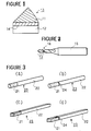
- the diamond tool is equipped with a tip 13 of composite materials which contains a layer 11 of hot-pressed diamond compact bonded to a supporting member 12 of hard sintered alloy.
- the tip 13 When a drill is manufactured from the tip 13 of composite materials, the tip 13 must be connected by any means to the top end of a shank 15 as shown in Fig. 2. However, the top end of the drilling tool is generally smaller in diameter than 1 mm, and in some cases, smaller than 0.5 mm. If the tip 13 is not very rigidly bonded to the shank 15 of a small diameter, the tip 13 tends to be easily removed at the bonded portion 16 from the shank 15 during the working of the tip 13 into a drill. Particularly, the hot-pressed diamond compact exhibits a high resistance to working. Then, the bonding strength obtained by silver brazing is insufficient for maintaining the tip to the shank in such working. Thus, it has been difficult to manufacture a high performance drill therefrom.
- a rigid bonding has not been obtained also by hot pressing the head member together with the supporting member.
- the blank for the microdrill must be of a small section and elongated form. It was practically impossible to hot press such an elongated member by the prior art technique.
- the supporting member or base member of the composite stick it must be of a high strength, particularly in the case of a microdrill.
- the integration density of the circuit board has become higher in these years, and this tendency will be enhanced. That is, the diameter of the machined hole in the circuit board will become smaller.
- microdrills of which the diameter is, for example, 0.1 mm or 0.3 mm will be demanded. Then, it should be noted that as the microdrill becomes smaller in diameter, it tends to be broken or bent easier. If the drill is bent before the duration of life of the diamond member, it is meaningless to use the expensive diamond.
- the supporting member is made of a soft or low rigidity material, it tends easily to be buckled so that a straight hole cannot be machined. Moreover, the supporting member of a soft material would wear out easily due to the abrasion by cuttings.
- EP ⁇ A ⁇ 0079243 there is disclosed a stick of composite material which has a hot-pressed super hard member containing more than 50 vol% of a diamond powder and/or a high pressure boron nitride powder.
- One end of the head member is bonded to a supporting member of predominantly tungsten carbide and a binder of an iron group material. The bonding between the head member and the supporting member is formed during the hot press process of the head member.
- EP ⁇ A ⁇ 0079243 discloses examples of such a stick in which the length of the head member lies within the range 0.3 t0 2.0 mm in the axial direction of the stick and in which the supporting member is more than five times longer in its axial direction than the head member.
- EP ⁇ A ⁇ 0079243 corresponds to the pre-characterising part of claim 1.
- the diameter of the stick in EP ⁇ A ⁇ 0079243 is relatively large in proportion to its axial length, making it unsuitable for use in the production of a microdrill.
- the present invention proposes that in a microdrill or micropunch sticker referred to above, the stick (23) after bonding and cutting in a axial direction by an electron spark method, has an elongate form having a sectional diameter or an equivalent sectional diameter not larger than 3mm; the supporting member (22) is at least twelve times longer in its axial direction than the hot-pressed-super-hard head member; and the tungsten carbide has a mean particle size of not more than 3 ⁇ m; and the mean particle size of the diamond and/or boron nitride powder is not more than 10 ⁇ m.
- the present invention permits readily and at low cost, the production of microdrills having an excellent wearing resistance and a high rigidity. It further permits a high performance microdrill with a long life, which may be suitably employed in machining circuit boards of low machinability such as the glass-expoxy circuit board.
- the stick of the present invention may also be used as a micropunch.
- the present invention provides a process as defined in claim 6
- the present inventors have succeeded in obtaining a stick of composite materials having a super-hard head member by hot pressing a composite compact of a large section with respect to its axial length and cutting the thus hot-pressed composite material block into a plurality of pieces in the form of an elongated stick by means of the electron spark cutting methods.
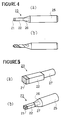
- Figs. 3 (a) to (d) illustrate respectively an embodiment of the stick of composite materials according to the present invention.
- the stick 23 of composite materials shown in Fig. 3 (a) is generally of a cylindrical form and comprises a super-hard hot-pressed head member 21 and a supporting member 22 bonded at one end thereof to the head member 21.
- the head member 21 is bonded to one end of the supporting member 22 through an interlayer 24.
- the sticks 23 shown in Figs. 3 (c) and (d) have a square section.
- the head member 21 is directly bonded to the supporting member 22, while, in Fig. 3 (d), the head member is bonded through an interlayer 24 to the supporting member 22.
- sectional shape of the stick of composite materials according to the present invention is not restricted only to circular or square form, and it may be of any other sectional form.
- the sectional diameter or the sectional equivalent diameter of the stick of composite materials must not be larger than 3 mm.
- a stick of composite materials having a diameter or an equivalent diameter larger than 3 mm is not appropriate as a blank of the microdrill. If such a stick of a large diameter is used as a blank of the microdrill, the chipping margin which is to be removed in forming cutting edges becomes unecomomically large.
- a composite material compact larger than 3 mm in diameter can be prepared by other process than the present invention.
- the super-hard hot-pressed head member of the stick must be of 0.3 to 2 mm in length according to the present invention. With a head member shorter than 0.3 mm in length, it is not possible to improve substantially the cutting performance of the drill. On the other hand, the use of a stick having a super-hard head member longer than 2 mm consumes a relatively large amount of an expensive material such as a diamond powder and thus it is uneconomical.
- the supporting member 22 must be at least twelve times longer in the axial direction of the stick than the head member 21, because the supporting member 22 is to be inserted in a hole disposed at the top end of the shank of a drill and a sufficiently long cutting edges is to be worked on its circumferential surface.
- a shank 25 for the drill is drilled at its top end to define a hole 26 having substantially the same diameter as the cylindrical stick 23.
- the cylindrical stick 23 is fitted into the hole 26 at its end portion and fixed therein.
- brazing material is poured in the hole 26 beforehand and then the end of the stick 23 is brazed to the shank 25.
- the circumferential surface of the stick 23 is ground to remove the surface layer in a depth of about 0.1 mm and the grooves and the cutting edges are formed to provide a microdrill as shown in Fig. 4 (b).
- Figs. 5 (a) and (b) illustrate an example of use of the square stick of the present invention.
- the end portion remote from the head member 21 of the supporting member 22 is worked by grinding into a cylindrical form 27 over a certain length as shown in Fig. 5 (a).
- the thus formed cylindrical end portion of the supporting member 22 is fitted into a hole 26 disposed at the top end of the shank 25, and brazed thereat.
- the circumferential surface of the square stick 23 is subjected to a finish working to a predetermined shape to provide a square punch as shown in Fig. 5 (b).
- the cylindrical stick of composite materials according to the present invention does not require complicated electron beam welding and has a strong and rigid integrated structure. Thus, it is possible to machine holes at high efficiency in a high performance circuit board such as a glass-epoxy circuit board.
- the composite material block may be of any sectional shape. But, the length in the axial direction, that is, in the pressing direction, must not be larger than three times, preferably two times the equivalent diameter thereof. If the axial length is longer than three times the, equivalent diameter of the section perpendicular to the axis, the pressure exerted to the block during the hot press tends to distribute irregulariy to thereby cause the buckling or curving of the block.
- the "equivalent diameter" of a section denotes the diameter of a circle of which surface is equal to the section in problem.
- the diamond powder and/or high pressure boron nitride powder have a mean particle size not greater than 10 ⁇ m to endow a high wearing resistance and a high rigidity to the resulting stick of composite materials.
- the cutting tool, drill and punch are not finished worked so shaply that a high performance is not attained.
- the layer containing diamond powder includes, for example, only a diamond powder, or a mixture containing more than 70 vol% of a diamond powder and the balance being a binder powder of which predominant constituent is Fe, Co or Ni.
- a mixture for the first layer there is a mixture containing not lower than 70 vol% of a diamond powder and a powder of WC ⁇ 5 to 15 vol% Co.
- the binding material contained in the second layer permeates in the first layer during the hot pressing of the first layer, thereby attaining the sintering of the first layer.
- the first layer which contains a high pressure boron nitride, may contain only the boron nitride powder or may contain not lower than 50 vol% of a high pressure boron nitride and, as a binder, a carbide, nitride and carbonitride of the Group 4a, 5a, 6a elements of the Periodic Table, and Al and/or
- the high pressure boron nitride includes the boron nitrides of wurtzite structure and cubic structure.
- the high pressure boron nitride powder can be hot pressed without binder to a hard compact body.
- the second layer for preparing the supporting member is be a so-called hard sintered alloy, or powder material therefor and a binder of iron metal such as Fe, Co and Ni.
- the second layer may be a sintered alloy or its powder material.
- a sintered alloy in the form of a solid block.
- Such a hard sintered alloy presents a high rigidity together with an excellent wearing resistance while maintaining a high strength.
- TiC and TaC which are usually contained in the hard sintered alloy for use as a tool for cutting steel materials, are not effective to improve the wearing resistance and tend to rather lower the strength of the alloy.
- the hard sintered alloy contains a low percentage of TaC, Cr 3 C 2 and VC, which are effective for restraining the grain growth of WC or for refining the grains of the alloy.
- Co and Ni are preferably used, and Co is the most preferable binder.
- the present inventors further conducted experiments and examination in order to improve the bending strength and the wearing resistance of the support member.
- the length of the supporting member must be at least twelve times larger than that of the head member. Thus, there is a reasonable possibility that the stick would be bent or buckled at the supporting member. The severe abrasion of the supporting member due to a high rotation of the drill must be also taken into account.
- one of the characteristics of the present invention resides in that the bonding between the head member and the supporting member is made during the hot press process of the head member. Then, the supporting member undergoes a high temperature and an ultra high pressure where the diamond or high pressure boron nitride is stable. That is, a sintering of WC ⁇ Co is conducted under vacuum at a temperature of 1300 to 1500°C, while the hot press of the diamond or high pressure boron nitride is conducted around the same temperature range but under an ultra high pressure of 40,000 to 50,000 atm. Accordingly, the ultra high pressure affects the mechanical properties of WC ⁇ Co, regardless of whether the second layer is in the sintered form or powdered form.
- the present inventors have conducted various experiments by hot pressing WC ⁇ Co sintered alloy under the above conditions, and found the following phenomena.
- the mechanical properties of WC ⁇ Co sintered alloy depend upon the content of Co and the particle size of WC crystals. But, if WC crystals having a particle size larger than 3 ⁇ m are exposed to a high temperature and an ultra high pressure, the WC crystals are broken to vary the mecanical properties drastically. Thus, the mean particle size of WC in the sintered alloy used as the second layer should be smaller than 3 ⁇ m.
- the present inventors found that with a Co content lower than 7 wt%, the bending strength lowers after the hot press of the high temperature and ultra high pressure, while the bending strength increases when the alloy contains more than 12 wt% of Co.
- the "holes” designates the holes ranging from several ⁇ m to several hundred ⁇ m. From the experience in the HIP process, it is supposed that such holes collapse due to the ultra high pressure or are filled with Co. Since the hot press is conducted at about the same temperature as the HIP but under a pressure higher by ten times than the HIP, such a phenomenon would be further intensified in the hot press according to the present invention.
- the Co phase in the WC ⁇ Co alloy is of FCC structure and is composed of almost pure Co, while it contains around 10 wt% of W when the C content is low. Then, in general, the WC ⁇ Co alloy of a high Co content is easily deformed.
- the strain-stress curve of such a high Co content WC ⁇ Co alloy is of low gradient, which means a low bending strength.
- the Co phase deposited at the eutectic temperature from the ternary eutectic crystal of Co ⁇ W ⁇ C contains about 20 wt% of W.
- W is deposited in the W phase from the ternary eutectic Co ⁇ W ⁇ C.
- the electric supply for heating means is cut off to cool the hot-pressed compact and then the pressing pressure is loosed. It means that when the compact is cooled to the eutectic temperature at which W whould deposit in the WC phase, the compact is still subjected to an ultra high pressure.
- the diffusion velosity of W is lowered in the solid phase and thus the deposition of W to the WC phase is prevented.
- Such assumption is confirmed by the fact that much of W is present in the state of solution in the Co phase of the WC ⁇ Co alloy of the support member of the stick of the present invention. Accordingly, the WC ⁇ Co alloy containing a high amount of Co which is considered to be too deformable under the usual condition exhibits a higher bending strength after the hot press of high temperature and ultra high pressure.
- the supporting member is composed of a hard sintered alloy of which the mean particle size of the carbide is smaller than 2 ⁇ m and which contains more than 12 wt% of a binder metal.
- One of the important characteristics of the stick of composite materials according to the present invention resides in that the bonding between the hot-pressed super-hard head member and the supporting member is made during the hot press of the head member. Accordingly, it is necessary to select the materials of the first and second layers so that these layers are bonded to each other by the hot press of the first layer.
- the bonding of the layers is easily attained because the binding agent of the iron group metal permeates from the second layer to the first layer at the high temperature and under the ultra high pressure.
- the powder of high pressure boron nitride can be sintered without any binding agent, and then it can be bonded to the support member during the sintering thereof.
- an interlayer having a thickness less than 0.5 mm is disposed between the first and second layers and these layers are hot pressed together.
- a preferable interlayer contains less than 70 vol% of high pressure boron nitride and the balance composed mainly of at least one selected from the group consisting of carbides, nitrides, carbonitrides and borides of the Group 4a element such as Ti, Zr and Hf and their mutual solid solutions, and more than 0.1 wt% of Al and/or Si.
- the second layer for the support member comprises at least two layers of materials arranged adjacent to each other in the axial direction thereof.
- the second layer is composed of a layer of WC ⁇ Co at the side remote from the head member, and a layer of a cermet of (Mo, W) C bonded by Ni or Co at the adjacent side to the head member.
- two layers of materials each intended for the head member are arranged respectively as the first layer at the upper and lower sides of the second layer and are hot pressed to provide a composite block which contains the first layers at the both sides.
- the composite block is then cut into at least two sticks each having the super-hard head members at the both ends.
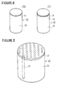
- the composite material block 33 comprises a thin layer 31 of hot-pressed diamond compact and a supporting layer 32 of hard sintered alloy bonded to the thin layer 31 at the top surface thereof as shown in Fig. 6 (a).
- the layer 31 is bonded to the supporting layer 32 through an interlayer 34 as shown in Fig. 6 (b).
- the composite material blocks shown in Figs. 6 (a) and (b) are of the cylindrical form, it may be of any other form such as a square timber.
- the composite material block 33 is cut in its axial direction into a plurality of sticks each having a diameter or an equivalent diameter not greater than 3 mm by means of an electron spark cutting method e.g. employing wire or pipe electrode.
- Figs. 8 (a) and (b) show an example of an electrode means which may be employed in the process of the present invention.
- the electrode means comprises a support plate 40 and three pipe electrodes 41a, 41b and 41c attached perpendicularly to the support plate 40 so as to cut off three composite sticks simultaneously.
- the pipe electrode 41 is, as shown in Fig. 3 (a), of a hollow cylindrical form and is disposed with a hole 42 for liberating the gasified material which is generated at the time of cutting.
- Fig. 9 (a) shows another type of the electrode means which comprises a plurality of pipe electrodes 41.
- Fig. 9 (b) shows the disposition of the pipe electrodes 41 with respect to the upper surface of the composite material block.
- the electrode means which may be employed in the process according to the present invention is not restricted to the types described in the above, and it may be of any other type with which the composite block can be cut off into a plurality of sticks, such as an electrode of a honeycomb form.
- the stick of composite materials of the present invention has been explained and defined by the chemical composition thereof before the hot press, but it is not explained as hot-pressed.
- the chemical composition and microscopic structure of the components of the composite stick that is, of the head member, supporting member and interlayer, vary delicately depending upon the temperature, pressing pressure and time duration of the hot press.
- the present invention will be more clearly and definitely understood if it is defined in terms of the chemical composition of the starting materials.
- the cylinder block was inserted in the ring to define therein a hollow space of 14 mm in diameter and 3 mm in depth in which the mixture of diamond powder was then charged and pressed to form a layer of 1.5 mm in thickness, and the upper portion of the hollow space was closed with the circular disc to form a container.
- the thus prepared container was charged in a hot press machine and the hot press was conducted at 1370°C, under a pressure of 55 kb and for 15 minutes.
- the circular disc was removed by grinding to obtain a composite block composed of a supporting layer of 12 mm in height, a hot pressed diamond layer of 1 mm in thickness bonded to the upper surface of the supporting layer and a ring of sintered alloy surrounding the circumference of the head layer and the supporting layer.
- the composite material block was subjected to the electron spark wire cutting method as shown in Fig. 7 to obtain cylindrical sticks of composite materials of 1 mm in diameter and 13 mm in length each of which contains a hot-pressed diamond head member of 1 mm in length bonded at the top end of the supporting member of WC ⁇ 12%Co.
- the above composite block was also cut by the electron spark method employing a electrode means shown in Fig. 9 (a) to obtain sticks of composite materials of the same configuration as the above mentioned composite sticks.
- a solution of the mixture of CBN powder was applied with a thickness of 50 ⁇ m on the top surface of the cylinder block and heated to remove the solvent.
- the cylinder block was then inserted in the ring to define therein a hollow space in which the mixture of diamond powder was charged and pressed to form a layer of 1.8 mm in thickness, and the upper portion of the hollow space was closed with the circular disc to form a container.
- the thus prepared container was charged in a hot press machine and the hot press was conducted at 1400°C, under a pressure of 55 kb and for 10 minutes.
- the circur disc was removed by grinding to obtain a composite block composed of a supporting layer of 18 mm in height, a hot pressed diamond layer of 1.2 mm in thickness bonded to the upper surface of the supporting layer through an interlayer of hot pressed CBN of a thickness of 25 ⁇ m and a ring of sintered alloy surrounding the circumference of the head layer and the supporting layer.
- the composite material block was subjected to the electron spark wire cutting method to obtain cylindrical sticks of composite materials of 2 mm in diameter and 19.2 mm in length each of which contains a hot pressed diamond head member of 1.2 mm in length bonded at the top end of the supporting member of WC ⁇ 12%Co through the interlayer of hot pressed CBN of 25 ⁇ m in thickness.
- the above composite block was also cut by the electron spark method employing a pipe electrode means to obtain sticks of composite materals of the same configuration as the above mentioned composite sticks.
- One of the above composite stick was fitted in a hole of a steel shank and brazed thereto.
- the outer surface of the stick was then finish worked by grinding to form a punch of a predetermined size.
- the obtained punch exhibited a serviced life time 100 times longer than the steel punch of the prior art in punching paper-bakelite circuit boards.
- a composite material block was prepared by conducting a hot press in the same manner as Example 2 except that a cylinder block of WC ⁇ 1%Cr 3 C 2 ⁇ 20%Co was employed in lieu of that of WC ⁇ 12%Co and that the mixture of diamond powder was charged in the container so as to obtain a hot pressed layer of 1 mm in thickness.
- the thus obtained composite block was subjected to the electron spark wire cutting method to obtain cylindrical composite sticks of 0.3 mm in diameter and 18.5 mm in length, each comprising a supporting member of WC ⁇ 1%Cr 3 C 2 ⁇ 20%Co having a mean particle size of 0.7 ⁇ m and a head member of hot pressed diamond of 0.5 mm in length bonded to the top end of the supporting member through an interlayer of hot pressed CBN of 25 ⁇ m in thickness.
- the mixture of diamond powder was charged in the recessed portion and pressed to form a layer of the powder of 2.3 mm in thickness and the recessed portion was closed with the circular disc to form a container.
- the thus prepared container was charged in a hot press machine and the hot press was conducted at 1400°C, under a pressure of 55 kb and for 15 minutes.
- the circur disc was removed by grinding to obtain a composite block composed of a hot pressed diamond layer of 1.5 mm in thickness in that recessed portion and a cylinder block of WC ⁇ 0.5%VC ⁇ 13%Co.
- the composite block was subjected to the electron spark wire cutting method to obtain cylindrical sticks of composite materials of 2 mm in diameter and 23.5 mm in length each of which contains a hot pressed diamond head member of 1,5 mm in length bonded at the top end of the supporting member of WC ⁇ 0.5%VC ⁇ 13%Co.
- the cylinder block of W alloy was inserted in the ring to define therein a hollow space of 14 mm in diameter and 3 mm in depth in which the mixture of CBN powder was then charged and pressed to form a layer of a thickness of 1.7 mm, and the upper portion of the hollow space was closed with the circular disc to form a container.
- the thus prepared container was charged in a hot press machine and the hot press was conducted at 1250°C, under a pressure of 50 kb and for 20 minutes.
- the circular disc was removed by grinding to obtain a composite block composed of a supporting layer of WC ⁇ 2%Tac ⁇ 16%Co of mean particle size 1 ⁇ m, 12 mm in height, a hot-pressed CBN layer of 1 mm in thickness bonded to the upper surface of the supporting layer and a ring of sintered alloy surrounding the circumference of the head layer and the supporting layer.
- the composite material block was subjected to the electron spark wire cutting method to obtain square sticks of composite materials of 1 mm in sectional side and 13 mm in length each of which contains a hot-pressed CBN head member of 1 mm in length bonded at the top end of the supporting member.
- the square stick was ground at one end portion of the sintered alloy side for a certain length to a cylindrical form as shown in Fig. 5 (a). Then, the cylindrical end portion was fitted in a hole of a steel shank and brazed thereto. The square stick was then finish worked to obtain a square punch of a predetermined size. It was conformed that the thus obtained square punch has an excellently long service life time as compared with the steel square punch of the prior art in punching the paper-bakerlite circuit boards.
Landscapes
- Engineering & Computer Science (AREA)
- Mechanical Engineering (AREA)
- Chemical & Material Sciences (AREA)
- Composite Materials (AREA)
- Manufacturing & Machinery (AREA)
- Materials Engineering (AREA)
- Powder Metallurgy (AREA)
Claims (11)
- Mikrobohrstab oder Mikrostanzstab (23) aus Verbundmaterialien, mit einem warmgepreßten superharten Kopfteil (21), das mehr als 50 Vol.-% Diamantpulver und/oder hochgepreßtes Bornitridpulver enthält und mit einem Halteteil (22) aus hauptsächlich Wolframkarbid und mit einem Bindemittel aus einem Metall der Eisengruppe, das in einer Menge von nicht weniger als 7 Gew.-% vorliegt und dessen eines Ende mit dem warmgepreßten superharten Kopfteil (21) verbunden ist, wobei die Länge des warmgepreßten superharten Kopfteils (21) zwischen 0,3 und 2,0 mm beträgt in Axialrichtung des Stabes (23) und die Verbindung zwischen dem warmgepreßten superharten Kopfteil (21) und dem Halteteil (22) während des Warmpressens des warmgepreßten superharten Kopfteils erfolgt, dadurch gekennzeichnet, daß der Stab (23) nach der Verbindung und dem Schneiden in Axialrichtung mittels eines Elektronenfunkenverfahrens eine langgestreckte Form aufweist, mit einem Querschnittsdurchmesser oder einem äquivalenten Kreisdurchmesser von nicht mehr als 3 mm aufweist, das Halteteil in seiner Axialrichtung mindestens 12 mal länger ist als das warmgepreßte superharte Kopfteil, und daß das Wolframkarbid eine mittlere Teilchengröße von nicht mehr als 3 µm aufweist und daß die mittlere Teilchengröße des Diamant- und/oder Bornitridpulvers nicht mehr als 10 µm beträgt.
- Stab (23) nach Anspruch 1, bei dem das Metall der Eisengruppe Co ist.
- Stab (23) nach einem der vorhergehenden Ansprüche, bei dem das Wolframkarbid in der hartgesinterten Legierung eine Teilchengröße von nicht mehr als 2 µm aufweist und der Gehalt an Bindemittel nicht geringer als 12 Gew.-% ist.
- Stab (23) nach einem der vorhergehenden Ansprüche, bei dem das warmgepreßte superharte Teil (21) mit dem Halteteil (22) über eine Zwischenschicht (24) verbunden ist, deren Dicke nicht größer als 0,5 mm ist.
- Stab (23) nach einem der vorhergehenden Ansprüche, bei dem der Stab (23) eine zylindrische Form aufweist.
- Verfahren zur Herstellung eines Mikrobohrstabs oder Mikrostanzstabs (23) aus Verbundmaterialien, mit einem warmgepreßten superharten Kopfteil (21), das mehr als 50 Vol.-% Diamantpulver und/oder hochgepreßtes Bornitridpulver enthält und mit einem Halteteil (22) aus hauptsächlich Wolframkarbid und einem Bindemittel aus einem Metall der Eisengruppe, das in einer Menge von nicht weniger als 7 Gew.-% vorliegt und dessen eines Ende mit dem warmgepreßten superharten Kopfteil (21) verbunden ist, wobei das Verfahren die folgenden Schritte umfaßt:Beladen einer Warmpresse mit zwei Materialschichten, in dem diese nebeneinander in Preßrichtung eingefüllt werden, eine der Schichten zur Herstellung des warmgepreßten superharten Kopfteils (21) und die andere Schicht zur Herstellung des Halteteils (22), das mit der erstgenannten Schicht während des Warmpressens zu verbinden ist,Warmpressen der beiden Materialschichten unter hohem Druck und hoher Temperatur, um die erstgenannte Schicht zu sintern, so daß ein Block aus Verbundmaterialien entsteht mit einer warmgepreßten superharten Schicht (21),
dadurch gekennzeichnet, daß
das Wolframkarbid eine mittlere Teilchengröße von nicht mehr als 3 µm aufweist; das Diamantpulver und/oder Bornitridpulver eine mittlere Teilchengröße von nicht mehr als 10 µm aufweist; und daß der Block aus Verbundmaterialien in Axialrichtung mittels eines Elektronen-Funken-Verfahrens in wenigstens zwei Stäbe aus Verbundmaterialien geschnitten wird, deren jeder einen Durchmesser von nicht mehr als 3 mm aufweist, wobei das Halteteil (22) in seiner Axialrichtung mindestens 12 mal länger ist als das warmgepreßte superharte Kopfteil. - Verfahren nach Anspruch 6, in dem das Metall er Eisengruppe Co ist.
- Verfahren nach Anspruch 6 oder 7, bei dem das Wolframkarbid in der hartgesinterten Legierung eine mittlere Teilchengröße von nicht mehr als 2 µm aufweist und der Gehalt an Bindemittel nicht größer als 12 Gew.-% ist.
- Verfahren nach einem der Ansprüche 6 bis 8, das ferner den Schritt des Aufbringens einer Zwischenschicht (24) zwischen den beiden Materialschichten aufweist, wobei die beiden Schichten warmgepreßt sind und über die Zwischenschicht (24) mit einer Dicke von weniger als 0,5 mm miteinander verbunden sind.
- Verfahren nach einem der Ansprüche 6 bis 9, bei dem der Block aus Verbundmaterialien in Axialrichtung mittels der Elektronen-Funken-Draht-Schneid-Methode geschnitten wird.
- Verfahren nach einem der Ansprüche 6 bis 9, bei dem der Block aus Verbundmaterialien in Axialrichtung mittels der Elektronen-Funken-Methode geschnitten wird unter Verwendung einer Elektrode in hohlzylindrischer Form.
Priority Applications (1)
| Application Number | Priority Date | Filing Date | Title |
|---|---|---|---|
| AT85304135T ATE49147T1 (de) | 1984-06-12 | 1985-06-11 | Stab aus verbundmaterialien und verfahren zu seiner herstellung. |
Applications Claiming Priority (8)
| Application Number | Priority Date | Filing Date | Title |
|---|---|---|---|
| JP120219/84 | 1984-06-12 | ||
| JP59120218A JPS60264371A (ja) | 1984-06-12 | 1984-06-12 | 複合焼結材料円柱体 |
| JP59120219A JPH0742488B2 (ja) | 1984-06-12 | 1984-06-12 | 複合焼結材料棒状体の製造方法 |
| JP120218/84 | 1984-06-12 | ||
| JP163095/84 | 1984-08-02 | ||
| JP59163095A JPH0742489B2 (ja) | 1984-08-02 | 1984-08-02 | 複合焼結材料からなる工具または硬質頭部を有する耐磨耗性部品 |
| JP60049559A JPS61209821A (ja) | 1985-03-13 | 1985-03-13 | 複合焼結材料棒状体の製造方法 |
| JP49559/85 | 1985-03-13 |
Publications (3)
| Publication Number | Publication Date |
|---|---|
| EP0168953A1 EP0168953A1 (de) | 1986-01-22 |
| EP0168953B1 EP0168953B1 (de) | 1990-01-03 |
| EP0168953B2 true EP0168953B2 (de) | 1998-07-01 |
Family
ID=27462375
Family Applications (1)
| Application Number | Title | Priority Date | Filing Date |
|---|---|---|---|
| EP85304135A Expired - Lifetime EP0168953B2 (de) | 1984-06-12 | 1985-06-11 | Stab aus Verbundmaterialien und Verfahren zu seiner Herstellung |
Country Status (5)
| Country | Link |
|---|---|
| US (1) | US4880707A (de) |
| EP (1) | EP0168953B2 (de) |
| KR (1) | KR920001585B1 (de) |
| CA (1) | CA1286510C (de) |
| DE (1) | DE3575092D1 (de) |
Cited By (2)
| Publication number | Priority date | Publication date | Assignee | Title |
|---|---|---|---|---|
| DE102009029715A1 (de) * | 2009-06-16 | 2010-12-23 | Komet Group Gmbh | Werkzeug zur Bearbeitung von Werkstücken |
| DE102015013687A1 (de) * | 2015-10-21 | 2017-04-27 | Audi Ag | Verfahren zum Herstellen mindestens eines Schweißstifts |
Families Citing this family (39)
| Publication number | Priority date | Publication date | Assignee | Title |
|---|---|---|---|---|
| ZA863979B (en) * | 1985-06-13 | 1987-01-28 | De Beers Ind Diamond | A method of making a blank of a drill bit |
| WO1987001634A1 (fr) * | 1985-09-16 | 1987-03-26 | Johann Steiner | Procede et dispositif de frittage sous pression pour la production d'outils diamants noyes dans du metal |
| IE59168B1 (en) * | 1985-11-04 | 1994-01-12 | De Beers Ind Diamond | Method of making a drill blank |
| GB8714340D0 (en) * | 1987-06-18 | 1987-07-22 | Manxtal Cutting Tools Ltd | Drill bit |
| EP0417302B1 (de) * | 1989-02-22 | 1997-07-02 | Sumitomo Electric Industries, Ltd. | Stickstoffenthaltender cermet |
| DE69205075T2 (de) * | 1991-06-25 | 1996-03-21 | Sumitomo Electric Industries | Hartgesinterter Presskörper für Werkzeuge. |
| GB2259263B (en) * | 1991-08-08 | 1995-11-22 | Habit Diamond Ltd | Wear resistant tools |
| US5273379A (en) * | 1992-01-23 | 1993-12-28 | Gn Tool Co., Ltd. | Blank material for drill and drill therefrom |
| DE4241140A1 (de) * | 1992-12-07 | 1994-06-09 | Krupp Widia Gmbh | Zerspannungswerkzeug |
| JPH06198504A (ja) * | 1993-01-07 | 1994-07-19 | Sumitomo Electric Ind Ltd | 高硬度焼結体切削工具 |
| DE4313154A1 (de) * | 1993-04-22 | 1994-10-27 | Demuth Alfred | Verfahren zur Herstellung von Schneidelementen für Bohr- oder Trennwerkzeuge |
| KR100502585B1 (ko) * | 2002-07-08 | 2005-07-20 | 일진디스플레이(주) | 주철 절삭용 고경도 소결체 및 그 제조방법 |
| JP4294687B2 (ja) * | 2003-06-30 | 2009-07-15 | コーニンクレッカ フィリップス エレクトロニクス エヌ ヴィ | 電気放電ランプ |
| CA2600396C (en) * | 2005-03-22 | 2014-09-02 | S. George Lesinski | Implanting a therapeutic appliance into the cochlea |
| US20100003094A1 (en) * | 2007-01-09 | 2010-01-07 | Irwin Industrial Tool Company | Drill bit |
| US20080166194A1 (en) * | 2007-01-09 | 2008-07-10 | Durfee Laverne R | Drill bit |
| US8070397B2 (en) * | 2008-02-19 | 2011-12-06 | Irwin Industrial Tool Company | Self feed bit |
| KR100928387B1 (ko) * | 2008-07-08 | 2009-11-23 | 베스너 주식회사 | 마이크로 드릴 및 그의 제조 방법 |
| US20100307640A1 (en) * | 2009-06-03 | 2010-12-09 | Durfee La Verne R | Cutting edge and cutting tool |
| ITBO20100069A1 (it) * | 2010-02-09 | 2011-08-10 | Cruing Italy S R L | Punta di foratura |
| GB201002375D0 (en) | 2010-02-12 | 2010-03-31 | Element Six Production Pty Ltd | A superhard tip, method for making same and tool comprising same |
| KR20110094660A (ko) * | 2010-02-17 | 2011-08-24 | 전주대학교 산학협력단 | 마이크로 절삭공구용 초경합금과 블랭크소재의 맞댐 연결구조 및 그 방법 |
| EP2502709B1 (de) | 2011-03-22 | 2017-02-01 | Black & Decker Inc. | Meissel |
| GB201109864D0 (en) | 2011-06-13 | 2011-07-27 | Element Six Ltd | Blank bodies for drill tips and methods for making same |
| US9167362B2 (en) | 2012-09-13 | 2015-10-20 | Otokinetics Inc. | Implantable receptacle for a hearing aid component |
| USD734792S1 (en) | 2013-03-15 | 2015-07-21 | Black & Decker Inc. | Drill bit |
| USD737875S1 (en) | 2013-03-15 | 2015-09-01 | Black & Decker Inc. | Drill bit |
| US9333564B2 (en) | 2013-03-15 | 2016-05-10 | Black & Decker Inc. | Drill bit |
| US9498824B2 (en) * | 2013-03-15 | 2016-11-22 | Sanfvik Intellectual Property Ab | Method of joining sintered parts of different sizes and shapes |
| DE102014207502B4 (de) * | 2014-04-17 | 2022-11-24 | Kennametal Inc. | Rotationswerkzeug sowie Werkzeugkopf |
| JP2017047502A (ja) * | 2015-09-02 | 2017-03-09 | 株式会社ディスコ | 切削砥石 |
| US10702926B2 (en) | 2016-10-07 | 2020-07-07 | Sumitomo Electric Hardmetal Corp. | Rotary cutting blade material and method for manufacturing the same |
| EP3375554B1 (de) * | 2016-11-15 | 2021-05-19 | Sumitomo Electric Hardmetal Corp. | Schneidwerkzeug |
| KR102188627B1 (ko) * | 2016-11-15 | 2020-12-08 | 스미또모 덴꼬오 하드메탈 가부시끼가이샤 | 절삭 공구 |
| EP3470156B1 (de) * | 2017-08-22 | 2022-10-26 | Sumitomo Electric Hardmetal Corp. | Drehschneidwerkzeug und herstellungsverfahren dafür |
| EP3533545A1 (de) * | 2018-03-01 | 2019-09-04 | AB Sandvik Coromant | Modularer schneidwerkzeugkörper und verfahren zur herstellung desselben |
| EP3984698A1 (de) * | 2020-10-15 | 2022-04-20 | ETA SA Manufacture Horlogère Suisse | Schneidwerkzeug |
| CN113586050B (zh) * | 2021-07-06 | 2023-08-22 | 太原理工大学 | 含金刚石的高耐磨截齿及其制备方法 |
| CN115365775B (zh) * | 2022-08-26 | 2024-04-16 | 北京尖刃智能科技有限公司 | 一种大长径比微小径超硬刀具棒料及其制备方法 |
Family Cites Families (13)
| Publication number | Priority date | Publication date | Assignee | Title |
|---|---|---|---|---|
| GB540392A (en) * | 1940-04-30 | 1941-10-15 | Wheel Trueing Tool Co | Improvements in or relating to methods of making diamond tools |
| US3362802A (en) * | 1964-06-25 | 1968-01-09 | Chromalloy American Corp | Combination machining tool and tool support having improved vibration damping characteristics |
| DE1602005B2 (de) * | 1966-12-06 | 1972-05-10 | Patent-Treuhand-Gesellschaft für elektrische Glühlampen mbH, 8000 München | Verfahren zur herstellung einer feinen bohrung in einem koerper aus material hoher schmelztemperatur |
| US3778180A (en) * | 1972-03-10 | 1973-12-11 | Federal Mogul Corp | Circuit board drill and method |
| AU512633B2 (en) * | 1976-12-21 | 1980-10-23 | Sumitomo Electric Industries, Ltd. | Sintered tool |
| US4235583A (en) * | 1978-03-23 | 1980-11-25 | General Motors Corporation | Extrusion die and method for making same |
| FR2423626B1 (fr) * | 1978-04-21 | 1985-11-29 | Christensen Inc Norton | Trepan de forage rotatif pour forages profonds |
| JPS5823353B2 (ja) * | 1978-05-17 | 1983-05-14 | 住友電気工業株式会社 | 切削工具用焼結体とその製造法 |
| AU529416B2 (en) * | 1978-07-04 | 1983-06-09 | Sumitomo Electric Industries, Ltd. | Diamond compact for a wire drawing die |
| US4403015A (en) * | 1979-10-06 | 1983-09-06 | Sumitomo Electric Industries, Ltd. | Compound sintered compact for use in a tool and the method for producing the same |
| GB2091763B (en) * | 1981-01-23 | 1985-07-10 | Sumitomo Electric Industries | Laminated sintered compositions including boron nitride |
| CA1216158A (en) * | 1981-11-09 | 1987-01-06 | Akio Hara | Composite compact component and a process for the production of the same |
| CA1248519A (en) * | 1984-04-03 | 1989-01-10 | Tetsuo Nakai | Composite tool and a process for the production of the same |
-
1985
- 1985-06-11 DE DE8585304135T patent/DE3575092D1/de not_active Expired - Lifetime
- 1985-06-11 EP EP85304135A patent/EP0168953B2/de not_active Expired - Lifetime
- 1985-06-11 KR KR1019850004091A patent/KR920001585B1/ko not_active Expired
- 1985-06-11 CA CA000483612A patent/CA1286510C/en not_active Expired - Lifetime
-
1988
- 1988-08-10 US US07/231,644 patent/US4880707A/en not_active Expired - Lifetime
Cited By (2)
| Publication number | Priority date | Publication date | Assignee | Title |
|---|---|---|---|---|
| DE102009029715A1 (de) * | 2009-06-16 | 2010-12-23 | Komet Group Gmbh | Werkzeug zur Bearbeitung von Werkstücken |
| DE102015013687A1 (de) * | 2015-10-21 | 2017-04-27 | Audi Ag | Verfahren zum Herstellen mindestens eines Schweißstifts |
Also Published As
| Publication number | Publication date |
|---|---|
| KR920001585B1 (ko) | 1992-02-20 |
| EP0168953B1 (de) | 1990-01-03 |
| EP0168953A1 (de) | 1986-01-22 |
| CA1286510C (en) | 1991-07-23 |
| KR860000113A (ko) | 1986-01-25 |
| DE3575092D1 (de) | 1990-02-08 |
| US4880707A (en) | 1989-11-14 |
Similar Documents
| Publication | Publication Date | Title |
|---|---|---|
| EP0168953B2 (de) | Stab aus Verbundmaterialien und Verfahren zu seiner Herstellung | |
| US4686080A (en) | Composite compact having a base of a hard-centered alloy in which the base is joined to a substrate through a joint layer and process for producing the same | |
| KR100749994B1 (ko) | 복합 회전도구 및 도구제작 방법 | |
| AU2001274230B2 (en) | Polycrystalline diamond with a surface depleted of catalyzing material | |
| EP0157625B1 (de) | Werkzeug aus Verbundwerkstoff | |
| EP0169081B1 (de) | Polykristalliner Diamantverbundkörper | |
| EP0180243B1 (de) | Schichtförmiger gesinterter Verbundkörper | |
| CA1233347A (en) | Printed circuit board drill and method of manufacture | |
| WO1998028455A1 (en) | Metal working drill/endmill blank | |
| IE930673A1 (en) | Encapsulation of segmented diamond compact | |
| GB2270492A (en) | Segmented diamond compact | |
| JPH0210843B2 (de) | ||
| JPH0742488B2 (ja) | 複合焼結材料棒状体の製造方法 | |
| JPH0525617B2 (de) | ||
| JPS61152308A (ja) | 硬質焼結体小径ドリル | |
| JPH049754B2 (de) | ||
| KR20250056530A (ko) | 극경암 시추용 코어 비트 및 그 제조방법 | |
| JPS6141703A (ja) | 複合焼結材料からなる工具または硬質頭部を有する耐磨耗性部品 | |
| HK1054712A (en) | Composite rotary tool and tool fabrication method | |
| HK1054220B (en) | Polycrystalline diamond with a surface depleted of catalyzing material | |
| IE930674A1 (en) | Segmented diamond compact |
Legal Events
| Date | Code | Title | Description |
|---|---|---|---|
| PUAI | Public reference made under article 153(3) epc to a published international application that has entered the european phase |
Free format text: ORIGINAL CODE: 0009012 |
|
| AK | Designated contracting states |
Designated state(s): AT BE CH DE FR GB IT LI NL |
|
| 17P | Request for examination filed |
Effective date: 19860501 |
|
| 17Q | First examination report despatched |
Effective date: 19870907 |
|
| GRAA | (expected) grant |
Free format text: ORIGINAL CODE: 0009210 |
|
| AK | Designated contracting states |
Kind code of ref document: B1 Designated state(s): AT BE CH DE FR GB IT LI NL |
|
| REF | Corresponds to: |
Ref document number: 49147 Country of ref document: AT Date of ref document: 19900115 Kind code of ref document: T |
|
| ET | Fr: translation filed | ||
| REF | Corresponds to: |
Ref document number: 3575092 Country of ref document: DE Date of ref document: 19900208 |
|
| ITF | It: translation for a ep patent filed | ||
| REG | Reference to a national code |
Ref country code: GB Ref legal event code: 746 |
|
| PLBI | Opposition filed |
Free format text: ORIGINAL CODE: 0009260 |
|
| ITPR | It: changes in ownership of a european patent |
Owner name: OFFERTA DI LICENZA AL PUBBLICO |
|
| 26 | Opposition filed |
Opponent name: DE BEERS INDUSTRIAL DIAMOND DIVISION (PROPRIETARY) Effective date: 19901003 |
|
| NLR1 | Nl: opposition has been filed with the epo |
Opponent name: DE BEERS INDUSTRIAL DIAMOND DIVISION (PROPRIETARY) |
|
| REG | Reference to a national code |
Ref country code: FR Ref legal event code: DL |
|
| ITTA | It: last paid annual fee | ||
| APAC | Appeal dossier modified |
Free format text: ORIGINAL CODE: EPIDOS NOAPO |
|
| APAC | Appeal dossier modified |
Free format text: ORIGINAL CODE: EPIDOS NOAPO |
|
| APAE | Appeal reference modified |
Free format text: ORIGINAL CODE: EPIDOS REFNO |
|
| APAC | Appeal dossier modified |
Free format text: ORIGINAL CODE: EPIDOS NOAPO |
|
| PLAW | Interlocutory decision in opposition |
Free format text: ORIGINAL CODE: EPIDOS IDOP |
|
| PUAH | Patent maintained in amended form |
Free format text: ORIGINAL CODE: 0009272 |
|
| STAA | Information on the status of an ep patent application or granted ep patent |
Free format text: STATUS: PATENT MAINTAINED AS AMENDED |
|
| 27A | Patent maintained in amended form |
Effective date: 19980701 |
|
| AK | Designated contracting states |
Kind code of ref document: B2 Designated state(s): AT BE CH DE FR GB IT LI NL |
|
| REG | Reference to a national code |
Ref country code: CH Ref legal event code: AEN Free format text: MAINTIEN DU BREVET DONT L'ETENDUE A ETE MODIFIEE |
|
| NLR2 | Nl: decision of opposition | ||
| ITF | It: translation for a ep patent filed | ||
| ET3 | Fr: translation filed ** decision concerning opposition | ||
| NLR3 | Nl: receipt of modified translations in the netherlands language after an opposition procedure | ||
| REG | Reference to a national code |
Ref country code: GB Ref legal event code: IF02 |
|
| PGFP | Annual fee paid to national office [announced via postgrant information from national office to epo] |
Ref country code: GB Payment date: 20020605 Year of fee payment: 18 |
|
| PGFP | Annual fee paid to national office [announced via postgrant information from national office to epo] |
Ref country code: FR Payment date: 20020610 Year of fee payment: 18 |
|
| PGFP | Annual fee paid to national office [announced via postgrant information from national office to epo] |
Ref country code: AT Payment date: 20020612 Year of fee payment: 18 |
|
| PGFP | Annual fee paid to national office [announced via postgrant information from national office to epo] |
Ref country code: CH Payment date: 20020617 Year of fee payment: 18 |
|
| PGFP | Annual fee paid to national office [announced via postgrant information from national office to epo] |
Ref country code: NL Payment date: 20020628 Year of fee payment: 18 |
|
| PGFP | Annual fee paid to national office [announced via postgrant information from national office to epo] |
Ref country code: BE Payment date: 20020821 Year of fee payment: 18 |
|
| PG25 | Lapsed in a contracting state [announced via postgrant information from national office to epo] |
Ref country code: GB Free format text: LAPSE BECAUSE OF NON-PAYMENT OF DUE FEES Effective date: 20030611 Ref country code: AT Free format text: LAPSE BECAUSE OF NON-PAYMENT OF DUE FEES Effective date: 20030611 |
|
| PG25 | Lapsed in a contracting state [announced via postgrant information from national office to epo] |
Ref country code: LI Free format text: LAPSE BECAUSE OF NON-PAYMENT OF DUE FEES Effective date: 20030630 Ref country code: CH Free format text: LAPSE BECAUSE OF NON-PAYMENT OF DUE FEES Effective date: 20030630 Ref country code: BE Free format text: LAPSE BECAUSE OF NON-PAYMENT OF DUE FEES Effective date: 20030630 |
|
| BERE | Be: lapsed |
Owner name: *SUMITOMO ELECTRIC INDUSTRIES LTD Effective date: 20030630 |
|
| PG25 | Lapsed in a contracting state [announced via postgrant information from national office to epo] |
Ref country code: NL Free format text: LAPSE BECAUSE OF NON-PAYMENT OF DUE FEES Effective date: 20040101 |
|
| GBPC | Gb: european patent ceased through non-payment of renewal fee |
Effective date: 20030611 |
|
| REG | Reference to a national code |
Ref country code: CH Ref legal event code: PL |
|
| PG25 | Lapsed in a contracting state [announced via postgrant information from national office to epo] |
Ref country code: FR Free format text: LAPSE BECAUSE OF NON-PAYMENT OF DUE FEES Effective date: 20040227 |
|
| NLV4 | Nl: lapsed or anulled due to non-payment of the annual fee |
Effective date: 20040101 |
|
| REG | Reference to a national code |
Ref country code: FR Ref legal event code: ST |
|
| PGFP | Annual fee paid to national office [announced via postgrant information from national office to epo] |
Ref country code: DE Payment date: 20040624 Year of fee payment: 20 |
|
| APAH | Appeal reference modified |
Free format text: ORIGINAL CODE: EPIDOSCREFNO |