EP0168960B1 - Détecteur optique de déplacements - Google Patents
Détecteur optique de déplacements Download PDFInfo
- Publication number
- EP0168960B1 EP0168960B1 EP85304208A EP85304208A EP0168960B1 EP 0168960 B1 EP0168960 B1 EP 0168960B1 EP 85304208 A EP85304208 A EP 85304208A EP 85304208 A EP85304208 A EP 85304208A EP 0168960 B1 EP0168960 B1 EP 0168960B1
- Authority
- EP
- European Patent Office
- Prior art keywords
- light
- fibre
- radiation
- lens
- reflector
- Prior art date
- Legal status (The legal status is an assumption and is not a legal conclusion. Google has not performed a legal analysis and makes no representation as to the accuracy of the status listed.)
- Expired
Links
Images
Classifications
-
- G—PHYSICS
- G01—MEASURING; TESTING
- G01D—MEASURING NOT SPECIALLY ADAPTED FOR A SPECIFIC VARIABLE; ARRANGEMENTS FOR MEASURING TWO OR MORE VARIABLES NOT COVERED IN A SINGLE OTHER SUBCLASS; TARIFF METERING APPARATUS; MEASURING OR TESTING NOT OTHERWISE PROVIDED FOR
- G01D5/00—Mechanical means for transferring the output of a sensing member; Means for converting the output of a sensing member to another variable where the form or nature of the sensing member does not constrain the means for converting; Transducers not specially adapted for a specific variable
- G01D5/26—Mechanical means for transferring the output of a sensing member; Means for converting the output of a sensing member to another variable where the form or nature of the sensing member does not constrain the means for converting; Transducers not specially adapted for a specific variable characterised by optical transfer means, i.e. using infrared, visible, or ultraviolet light
- G01D5/268—Mechanical means for transferring the output of a sensing member; Means for converting the output of a sensing member to another variable where the form or nature of the sensing member does not constrain the means for converting; Transducers not specially adapted for a specific variable characterised by optical transfer means, i.e. using infrared, visible, or ultraviolet light using optical fibres
Definitions
- This invention relates to optical displacement sensors and has application in pressure sensors in which pressure is indicated by the displacement of a diaphragm.
- optical displacement sensor comprises an optical fibre the tip of which is positioned to direct light transmitted along the fibre onto a reflector the displacement of which is to be measured.
- the reflector may comprise a diaphragm or membrane having a reflecting surface and forming part of a pressurised enclosure.
- the optical system is arranged so that the change in the amount of light reflected back is a measure of the displacement of the reflector.
- the reflected light is measured and its value indicated to give a measure of displacement or pressure.
- the optical system is arranged so that the change in reflected light is linearly related to displacement.
- a fibre-optic displacement sensor which has two light sources of different wavelengths which are controlled to generate light pulses time delayed with respect to each other.
- One beam, the signal beam is modified in amplitude by the displacement of a sensor while the other beam, the reference beam, is unaffected.
- the light pulses follow a common path to a frequency sensitive filter in which the transmittivity at one frequency depends on displacement but is unaffected at the other frequency.
- the frequency sensitive filter is unlikely to be completely displacement insensitive at the reference frequency.
- a dichroic reflector is used to reflect the reference beam, but not the signal beam. This isolates the path of the reference beam from the displacement sensor itself and does not correct for aging of the sensor.
- an optical displacement sensor comprises a reflector surface the displacement of which is to be measured, a radiation source coupled to an optical fibre one end of which is directed onto the surface so as to illuminate the surface with radiation from the source, signal detector means for detecting and measuring radiation reflected back from the reflector and arranged so that the amount of the reflected radiation detected is a function of the position of the surface, and reference detector means for detecting and measuring radiation reflected back from the said surface, and lens means positioned and arranged so that the amount of the reflected radiation detected in the reference detector means is independent of the position of the surface.
- means may be provided for calculating the change in the magnitude of the signal detected in the signal detector means due to displacement of the reflector, and means for dividing the said calculated change in magnitude by the magnitude of the signal detected in the reference detector means.
- a separate radiation source coupled to a second optical fibre one end of which is positioned to direct radiation onto and receive radiation reflected back from the reflector surface, which fibre is coupled to the reference detector means.
- a single optical fibre is provided and light therefrom is directed onto two different colour filters in different positions, the light from one colour filter following an optical path to the reflector surface and back such that the amount of light reflected back to the fibre is dependent on the position of the surface and the light from the other colour filter following a different optical path to the reflector surface and back such that the magnitude of the reflected light of the other colour is independent of the position of the reflector surface.
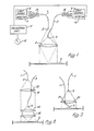
- Figure 1, 2 and 3 show embodiments of the invention utilising two optical fibres
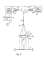
- Figure 4 illustrates an embodiment of the invention using a common optical fibre.
- an optical displacement sensor comprising a main fibre 1 to which is coupled a light emitting source 2 such as a light emitting diode through one arm of a Y-coupler 17. It is desired to measure the displacement of a reflective membrane 3 which may. form part of a gastight enclosure for example.
- a lens 4 is provided of focal length f and the tip 5 of fibre 1 is positioned at a distance 2f from the lens and likewise the lens is positioned at a distance 2f from membrane 3.
- the light emitted from tip 5 of fibre 1 will thus be brought to a focus on the surface of the membrane and displacement of membrane 3 from the focal point will cause a change in the magnitude of the light reflected back from membrane 3 through lens 4 to tip 5 of fibre 1.
- For small deflections at least the change in the amount of light reflected back to tip 5 of fibre 1 is linearly related to the displacement of membrane 3.
- the reflected light will return along fibre 1 and be detected in a detector 6 coupled to the other arm of Y-coupler 17.
- the change in the amount of light that is detected in detector 6 will therefore be proportional to the displacement of membrane 3 for small deflections of the membrane from the focus of the light passing through lens 4.
- this relationship will be affected by any deterioration in the quality of the reflecting surface of membrane 3.
- a second optical fibre 7 is provided energised from a light source 8 coupled to fibre 7 through one arm of a Y-coupler 18.
- the tip 9 of fibre 7 is positioned at a distance f from lens 4 so that the light therefrom emerges as a parallel ray and is directed onto the surface of reflector 3.
- Reflector 3 will return this light back to the focal point of lens 4 where the tip 9 of fibre 7 is positioned and this light will pass back along fibre 7 and through the other arm of coupler 18 to a light detector 10.
- the magnitude of the signal detected in detector 6 can be calibrated in terms of the displacement of the membrane 3. Provided there is no change in the reflective properties of membrane 3 then this calibration will remain valid throughout the lifetime of the apparatus. In practice, however, it is likely that the reflective quality of membrane 3 will deteriorate.
- the signal obtained from detector 6 is processed by being divided by the magnitude of the signal from detector 10 in a suitable processing unit 11. It is the processed signal output from unit 11 that is then used for indicating the displacement of membrane 3, for example in a meter 12 which can be calibrated in terms of displacement or pressure. Any deterioration of the quality of the reflective surface of membrane which will reduce the signal received by detector 6 will cause a corresponding reduction in the signal in detector 10 so that the resultant quotient as displayed in meter 12 will remain constant for a given displacement of membrane 3.
- fibres 1 and 7 are of the same type and preferably originate from the same production batch. Further, they are preferably a twin cable.
- the magnitude of the reflected signals may also change due to ageing of the light emitting diodes 2 and 8. Provided that each of these items are appropriately matched and paired then any deterioration of one of these items will be matched by equal deterioration of the other so that there will be a corresponding reduction in the signal in detector 10 which can be used likewise to compensate for the signal in detector 6.
- tip 5 of fibre 1 is shown as being positioned at a distance 2f from lens 4. However, this is not necessary and tip 5 can be positioned at any convenient distance from lens 4 provided that its image is formed in the plane of membrane 3. However, a distance of 2f corresponds to unit magnification and to the minimum total length between tip 5 and membrane 3.
- a multiple lens arrangement can be provided and one such arrangement is shown in Figure 2 in which like parts have like reference numerals to Figure 1 except that the lens 4 of Figure 1 is now replaced by a system of three lenses 13, 14 and 15.
- Lens 13 is positioned at a distance equal to its focal length from tip 5 so as to produce a collimated beam of light which is then brought to a focus in the plane of membrane 3 by the objective lenses 14 and 15.
- the function of lens 13 is to ensure a constant light gathering capability for the light flux emitted from tip 5 regardless of the objective lens arrangement that is selected.
- the arrangement of Figure 2 with its separate objective lens arrangement has a greater sensitivity than the Figure 1 arrangement.
- FIG. 3 A simpler optical system is shown in Figure 3 in which only one lens 20 is used solely for the purpose of collimating the reference beam emerging from tip 9 of fibre 7.
- Fibre 1 passes through a hole 21 drilled in lens 20 and the light reflected back into fibre 1 for measuring purposes depends solely on the numerical aperture of fibre 1. It is not essential to pass fibre 1 through lens 21 and it could by-pass the lens altogether.
- the optical fibre 7 carrying the reference light is not independently directed on to membrane 3 but instead its output and the output from fibre 1 are both coupled through a Y-coupler 35 to a common optical fibre 36 so that light from both sources 2 and 8 emerge from the end of tip 37 of fibre 36.
- sources 2 and 8 have different wavelengths L1 and L2.
- L1 might be green light and L2 might be red light, although other wavelengths, which may be closer together, can be used.
- a bifocal lens 30 is provided on to which the light of the two wavelengths L1 and L2 emerging from tip 37 is directed.
- Bifocal lens 30 has a centre part 31 of shorter focal length than its outer annular part 32.
- Colour filters 33 and 34 are positioned just in front of lens 30.
- Filter 33 passes light of wavelength L1 only and coincides in extent with the area of the inner shorter focal length part 31 of lens 30.
- Filter 34 is annular in shape and is of the same extent as outer annular part 32 of lens 30. Filter 34 passes light of wavelength L2 only.
- the distance between tip 37 and lens 30 is equal to 2f1 where f1 is the focal length of part 31 and is also equal to f2 the focal length of part 32 of lens 30.
- f1 is the focal length of part 31 and is also equal to f2 the focal length of part 32 of lens 30.
- two separate light sources 2 and 8 are shown. These may be replaced by a single light source and a beam splitter having two outputs respectively feeding the Y-couplers 17 and 18. Whether two light sources or a single light source is provided it is desirable to ensure that the light outputs to the two optic fibres are of equal amplitude or at least have a constant amplitude ratio.
Landscapes
- Physics & Mathematics (AREA)
- General Physics & Mathematics (AREA)
- Length Measuring Devices By Optical Means (AREA)
- Measurement Of Optical Distance (AREA)
- Measuring Fluid Pressure (AREA)
- Optical Transform (AREA)
Claims (5)
Applications Claiming Priority (2)
| Application Number | Priority Date | Filing Date | Title |
|---|---|---|---|
| GB848415128A GB8415128D0 (en) | 1984-06-14 | 1984-06-14 | Optical displacement sensors |
| GB8415128 | 1984-06-14 |
Publications (3)
| Publication Number | Publication Date |
|---|---|
| EP0168960A2 EP0168960A2 (fr) | 1986-01-22 |
| EP0168960A3 EP0168960A3 (en) | 1987-11-19 |
| EP0168960B1 true EP0168960B1 (fr) | 1990-09-19 |
Family
ID=10562402
Family Applications (1)
| Application Number | Title | Priority Date | Filing Date |
|---|---|---|---|
| EP85304208A Expired EP0168960B1 (fr) | 1984-06-14 | 1985-06-13 | Détecteur optique de déplacements |
Country Status (4)
| Country | Link |
|---|---|
| US (1) | US4711578A (fr) |
| EP (1) | EP0168960B1 (fr) |
| DE (1) | DE3579764D1 (fr) |
| GB (2) | GB8415128D0 (fr) |
Families Citing this family (18)
| Publication number | Priority date | Publication date | Assignee | Title |
|---|---|---|---|---|
| GB8610654D0 (en) * | 1986-05-01 | 1986-08-20 | Bicc Plc | Movement detection |
| IT1216609B (it) * | 1988-04-21 | 1990-03-08 | Pirelli Cavi Spa | Sensore ottico di posizione. |
| FI884142A7 (fi) * | 1988-09-08 | 1990-03-09 | Vaisala Oy | Valosironnan mittausjärjestelmä. |
| DE3841742A1 (de) * | 1988-12-10 | 1990-06-13 | Hueser Teuchert Dorothee | Koordinatenmesstaster mit absolutinterferometrischem beruehrungslosem messprinzip |
| EP0419082B1 (fr) * | 1989-09-21 | 1996-04-17 | Stanley Electric Corporation | Appareil de mesure optique de distance |
| US5144833A (en) * | 1990-09-27 | 1992-09-08 | International Business Machines Corporation | Atomic force microscopy |
| SE513943C2 (sv) * | 1992-07-02 | 2000-11-27 | Celsiustech Electronics Ab | Optisk vinkelmätare |
| GB9307484D0 (en) * | 1993-04-08 | 1993-06-02 | Lucas Ind Plc | Optical displacement sensor |
| US5612785A (en) * | 1996-01-03 | 1997-03-18 | Servo Robot Inc. | Twin sensor laser probe |
| EP1175244B1 (fr) * | 1999-04-07 | 2009-06-03 | Loma Linda University Medical Center | Systeme de surveillance des mouvements du patient dans le cadre d'une therapie protonique |
| US6346987B1 (en) | 2000-09-27 | 2002-02-12 | The United States Of America As Represented By The Secretary Of The Navy | Micro-optical position indicator |
| WO2003039212A1 (fr) | 2001-10-30 | 2003-05-08 | Loma Linda University Medical Center | Procede et dispositif de radiotherapie |
| KR100450815B1 (ko) * | 2002-02-01 | 2004-10-01 | 삼성전자주식회사 | 조명계 및 이를 채용한 프로젝션 디스플레이 장치 |
| US7173265B2 (en) | 2003-08-12 | 2007-02-06 | Loma Linda University Medical Center | Modular patient support system |
| RU2272985C1 (ru) * | 2004-08-16 | 2006-03-27 | Государственное образовательное учреждение высшего профессионального образования Санкт-Петербургский государственный горный институт им. Г.В. Плеханова | Волоконно-оптический датчик перемещений |
| DE102004053659B3 (de) * | 2004-11-03 | 2006-04-13 | My Optical Systems Gmbh | Verfahren und Vorrichtung zur berührungslosen Erfassung von thermischen Eigenschaften einer Objektoberfläche |
| US8632448B1 (en) | 2009-02-05 | 2014-01-21 | Loma Linda University Medical Center | Proton scattering analysis system |
| CA2829094A1 (fr) | 2011-03-07 | 2012-11-29 | Loma Linda University Medical Center | Systemes, dispositifs et procedes relatifs a l'etalonnage d'un scanner de tomographie par emission de protons calculee par ordinateur |
Family Cites Families (9)
| Publication number | Priority date | Publication date | Assignee | Title |
|---|---|---|---|---|
| US3327584A (en) * | 1963-09-09 | 1967-06-27 | Mechanical Tech Inc | Fiber optic proximity probe |
| DE1473780A1 (de) * | 1965-12-30 | 1969-03-13 | Bbc Brown Boveri & Cie | Einrichtung zur beruehrungslosen Messung von Konturen |
| US3940608A (en) * | 1974-02-04 | 1976-02-24 | Mechanical Technology Incorporated | Fiber optic displacement measuring apparatus |
| CH615757A5 (fr) * | 1977-06-06 | 1980-02-15 | Balzers Hochvakuum | |
| GB2077421B (en) * | 1980-05-31 | 1983-10-12 | Rolls Royce | Displacement sensing |
| US4515479A (en) * | 1980-07-29 | 1985-05-07 | Diffracto Ltd. | Electro-optical sensors with fiber optic bundles |
| US4487206A (en) * | 1982-10-13 | 1984-12-11 | Honeywell Inc. | Fiber optic pressure sensor with temperature compensation and reference |
| US4596925A (en) * | 1982-10-27 | 1986-06-24 | The Foxboro Company | Fiber optic displacement sensor with built-in reference |
| GB8405638D0 (en) * | 1984-03-03 | 1984-04-04 | Monicell Ltd | Optical transducer and measuring device |
-
1984
- 1984-06-14 GB GB848415128A patent/GB8415128D0/en active Pending
-
1985
- 1985-06-13 GB GB08514998A patent/GB2160310B/en not_active Expired
- 1985-06-13 EP EP85304208A patent/EP0168960B1/fr not_active Expired
- 1985-06-13 DE DE8585304208T patent/DE3579764D1/de not_active Expired - Lifetime
- 1985-06-13 US US06/744,383 patent/US4711578A/en not_active Expired - Fee Related
Also Published As
| Publication number | Publication date |
|---|---|
| DE3579764D1 (de) | 1990-10-25 |
| GB2160310B (en) | 1988-05-18 |
| GB8514998D0 (en) | 1985-07-17 |
| GB2160310A (en) | 1985-12-18 |
| EP0168960A3 (en) | 1987-11-19 |
| EP0168960A2 (fr) | 1986-01-22 |
| US4711578A (en) | 1987-12-08 |
| GB8415128D0 (en) | 1984-07-18 |
Similar Documents
| Publication | Publication Date | Title |
|---|---|---|
| EP0168960B1 (fr) | Détecteur optique de déplacements | |
| US5017772A (en) | Fiber optic probe sensor for measuring target displacement | |
| US4356396A (en) | Fiber optical measuring device with compensating properties | |
| US4432640A (en) | Adjustment and testing device for a laser ranging system | |
| US4653905A (en) | Fiber optic range finder systems | |
| US4919535A (en) | Reflectance measuring apparatus for making contactless measurements | |
| US5268739A (en) | Laser apparatus for measuring the velocity of a fluid | |
| EP0124533A1 (fr) | Capteur de deplacement a fibre optique a reference integree | |
| US6233053B1 (en) | Dual standard gloss sensor | |
| US4974961A (en) | Optical fibre measuring system | |
| KR20190038994A (ko) | 공초점 계측 장치 | |
| GB2077421A (en) | Displacement sensing | |
| EP0168182B1 (fr) | Appareil de mesure optique | |
| EP0167277B1 (fr) | Appareil de mesure de microdéplacements | |
| US6353216B1 (en) | Confocal measurement and diagnostic system | |
| JPH08122211A (ja) | 眼鏡レンズ測定装置 | |
| WO2012170275A1 (fr) | Systèmes confocaux à multiples longueurs d'onde couplées pour mesurer des distances | |
| US4929077A (en) | Interferometric range finder | |
| KR910001840B1 (ko) | 변위 탐지 | |
| US5739526A (en) | Fibre-optic photoelectric beam device having a transmitting optical unit for detecting a moving object through a control district | |
| US5418361A (en) | Optical displacement sensor employing reflected light of four wavelengths to determine displacement and the refractive index of the medium | |
| GB2086572A (en) | Differential pressure measuring apparatus | |
| US4946275A (en) | Fiber optic position transducer | |
| US4947038A (en) | Process and arrangement for optically measuring a physical quantity | |
| JPH068724B2 (ja) | 光学的検出装置 |
Legal Events
| Date | Code | Title | Description |
|---|---|---|---|
| PUAI | Public reference made under article 153(3) epc to a published international application that has entered the european phase |
Free format text: ORIGINAL CODE: 0009012 |
|
| AK | Designated contracting states |
Designated state(s): DE FR IT NL |
|
| 17P | Request for examination filed |
Effective date: 19860602 |
|
| PUAL | Search report despatched |
Free format text: ORIGINAL CODE: 0009013 |
|
| AK | Designated contracting states |
Kind code of ref document: A3 Designated state(s): DE FR IT NL |
|
| 17Q | First examination report despatched |
Effective date: 19890918 |
|
| GRAA | (expected) grant |
Free format text: ORIGINAL CODE: 0009210 |
|
| AK | Designated contracting states |
Kind code of ref document: B1 Designated state(s): DE FR IT NL |
|
| ITF | It: translation for a ep patent filed | ||
| ET | Fr: translation filed | ||
| REF | Corresponds to: |
Ref document number: 3579764 Country of ref document: DE Date of ref document: 19901025 |
|
| PLBE | No opposition filed within time limit |
Free format text: ORIGINAL CODE: 0009261 |
|
| STAA | Information on the status of an ep patent application or granted ep patent |
Free format text: STATUS: NO OPPOSITION FILED WITHIN TIME LIMIT |
|
| 26N | No opposition filed | ||
| PGFP | Annual fee paid to national office [announced via postgrant information from national office to epo] |
Ref country code: FR Payment date: 19920515 Year of fee payment: 8 |
|
| ITTA | It: last paid annual fee | ||
| PGFP | Annual fee paid to national office [announced via postgrant information from national office to epo] |
Ref country code: NL Payment date: 19920630 Year of fee payment: 8 |
|
| ITPR | It: changes in ownership of a european patent |
Owner name: CESSIONE;BRITISH TECHNOLOGY GROUP LIMITED |
|
| PGFP | Annual fee paid to national office [announced via postgrant information from national office to epo] |
Ref country code: DE Payment date: 19920831 Year of fee payment: 8 |
|
| REG | Reference to a national code |
Ref country code: FR Ref legal event code: TP |
|
| NLS | Nl: assignments of ep-patents |
Owner name: BRITISH TECHNOLOGY GROUP LTD TE LONDEN, GROOT-BRIT |
|
| PG25 | Lapsed in a contracting state [announced via postgrant information from national office to epo] |
Ref country code: NL Effective date: 19940101 |
|
| NLV4 | Nl: lapsed or anulled due to non-payment of the annual fee | ||
| PG25 | Lapsed in a contracting state [announced via postgrant information from national office to epo] |
Ref country code: FR Effective date: 19940228 |
|
| PG25 | Lapsed in a contracting state [announced via postgrant information from national office to epo] |
Ref country code: DE Effective date: 19940301 |
|
| REG | Reference to a national code |
Ref country code: FR Ref legal event code: ST |