EP0169177B1 - Vorrichtung zum Anstreichen von Laternenpfählen oder dergleichen - Google Patents
Vorrichtung zum Anstreichen von Laternenpfählen oder dergleichen Download PDFInfo
- Publication number
- EP0169177B1 EP0169177B1 EP85830161A EP85830161A EP0169177B1 EP 0169177 B1 EP0169177 B1 EP 0169177B1 EP 85830161 A EP85830161 A EP 85830161A EP 85830161 A EP85830161 A EP 85830161A EP 0169177 B1 EP0169177 B1 EP 0169177B1
- Authority
- EP
- European Patent Office
- Prior art keywords
- pole
- rollers
- painting
- fact
- carriage structure
- Prior art date
- Legal status (The legal status is an assumption and is not a legal conclusion. Google has not performed a legal analysis and makes no representation as to the accuracy of the status listed.)
- Expired
Links
Images


Classifications
-
- B—PERFORMING OPERATIONS; TRANSPORTING
- B05—SPRAYING OR ATOMISING IN GENERAL; APPLYING FLUENT MATERIALS TO SURFACES, IN GENERAL
- B05C—APPARATUS FOR APPLYING FLUENT MATERIALS TO SURFACES, IN GENERAL
- B05C11/00—Component parts, details or accessories not specifically provided for in groups B05C1/00 - B05C9/00
- B05C11/10—Storage, supply or control of liquid or other fluent material; Recovery of excess liquid or other fluent material
-
- B—PERFORMING OPERATIONS; TRANSPORTING
- B05—SPRAYING OR ATOMISING IN GENERAL; APPLYING FLUENT MATERIALS TO SURFACES, IN GENERAL
- B05C—APPARATUS FOR APPLYING FLUENT MATERIALS TO SURFACES, IN GENERAL
- B05C1/00—Apparatus in which liquid or other fluent material is applied to the surface of the work by contact with a member carrying the liquid or other fluent material, e.g. a porous member loaded with a liquid to be applied as a coating
- B05C1/02—Apparatus in which liquid or other fluent material is applied to the surface of the work by contact with a member carrying the liquid or other fluent material, e.g. a porous member loaded with a liquid to be applied as a coating for applying liquid or other fluent material to separate articles
- B05C1/022—Apparatus in which liquid or other fluent material is applied to the surface of the work by contact with a member carrying the liquid or other fluent material, e.g. a porous member loaded with a liquid to be applied as a coating for applying liquid or other fluent material to separate articles to the outer surface of hollow articles
-
- Y—GENERAL TAGGING OF NEW TECHNOLOGICAL DEVELOPMENTS; GENERAL TAGGING OF CROSS-SECTIONAL TECHNOLOGIES SPANNING OVER SEVERAL SECTIONS OF THE IPC; TECHNICAL SUBJECTS COVERED BY FORMER USPC CROSS-REFERENCE ART COLLECTIONS [XRACs] AND DIGESTS
- Y10—TECHNICAL SUBJECTS COVERED BY FORMER USPC
- Y10S—TECHNICAL SUBJECTS COVERED BY FORMER USPC CROSS-REFERENCE ART COLLECTIONS [XRACs] AND DIGESTS
- Y10S118/00—Coating apparatus
- Y10S118/11—Pipe and tube outside
Definitions
- the invention relates to a pole painting apparatus comprising a carriage structure upwardly and downwardly movable along the pole to be painted, on said carriage structure a carousel arrangement able to rotate around the pole, painting means rotatable with said carousel arrangement, and motor means for the movement of the apparatus along the pole as well as motor means for driving into rotation said carousel arrangement.
- a pole painting apparatus of this type is disclosed in FR-A-1 546 499.
- a circular support is fixed, whereon a gear with external toothing is placed, which inwardly has bristles forming an annular brush coaxial with the pole for distribution of the paint supplied by means of a gear pump and picked up from a container.
- the bristles are forming an annular brush, the inside diameter of which is fixed. This means that when painting poles of different diameter, and/or sections with variable diameter of the same pole (as it always occurs in practice), the bristles undergo a smaller or bigger deformation depending on the dimensions of the pole to be painted. This leads to a painting which is not of constant quality, due to the fact that the deformation causes the aptitude of the bristles to distribute the paint - and therefore the quality of the layer of paint to be distributed - to vary. Further, the variability of the acceptable pole dimensions is limited by the capability of the bristles to be bent. Beyond a certain diameter of the pole, the annular brush must be substituted.
- a pole coating apparatus for manual painting of poles which comprises a hood axially movable along the pole to be painted by means of a rod.
- Said hood is provided with a set of paint distributors circumferentially disposed around the pole to be painted, presenting a plurality of paint supply openings, and with rollers rotating around substantially horizontal axes.
- the paint supplied by this apparatus is for a great part lost, particularly in the case of poles of small diameter, and smeares the whole apparatus.
- the adjustment of the apparatus with respect to the pole diameter is very difficult, as it requests the disassembly and remounting of all the paint distribution means.
- said painting means comprises a spraying unit for the ejection of the paint oriented from the periphery substantially radially towards the pole and at least a pair of rollers symmetrically placed with respect to said spraying unit, said rollers resting on said pole and rotating around axes parallel to the pole axis during rotation of said carousel arrangement.
- the rollers form a curtain for the front of ejected paint, thus avoiding dispersion and gathering the intercepted paint onto the surface to be painted. If gathering of the ejected paint is not necessary, the rotters may be kept spaced apart while the painting apparatus is moving downwards along the pole.
- the rollers have a double movement with respect to the surface to be painted, namely a first rolling movement and a second sliding movement along the pole axis.
- rollers rest on the surface of the pole and therefore permit, together with the use of the spraying unit, to paint poles of different diameters and/or sections of varying diameter of a same pole without substituting any part of the apparatus. This results in a very felicitous painting action with uniform distribution of paint.
- a second pair of rollers may be provided, with axes parallel to the axes of the first pair of rollers and rolling in contact with them.
- the rollers are carried by arms urged towards the pole by elastic means.
- the arms carrying the rollers should be able to be kept wide open.
- It is a further object of the present invention to provide an apparatus for the maintenance of poles comprising a carriage structure upwardly and downwardly movable along the pole to be painted, on said carriage structure a carousel arrangement able to rotate around the pole, motor means for the movement of the apparatus along the pole as well as motor means for driving into rotation said carousel arrangement, said apparatus being suitable for the maintenance of poles of different diameter and/or of poles having sections of varying diameter.
- said apparatus comprises at least a pair of support arms located on said carousel arrangement biased toward said pole, each support arm carrying at least a brush resting on said pole, and motor means being provided to drive into rotation said brushes.
- Said brushes may rotate around axes perpendicular to the pole axis, or around axes parallel to said pole axis.
- said apparatus for the maintenance of poles further comprises means able to keep said arms spaced apart, in order to permit lifting of the carriage structure along the pole.
- an installed pole is indicated, along which a painting operation and, possibly, a preliminary operation of brush cleaning or the like are to be performed.
- the pole may be cylindrical or conical and may also present tapers as is shown in Fig. 1 where the pole P is made up of two sections P1 and P2 which are step-wise jointed.
- the apparatus may be utilized for poles of even relatively different diameters.
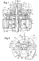
- Numeral 1 indicates a main structure of the apparatus, which makes up a casing 3, within which members of the driving rollers system are received for the vertical displacement along the pole.
- the casing 3 is developed like an open ring having a wide opening 5 which projects radially from the central open space of the annular structure 3 up to the periphery of the same structure ; this permits the fitting of the casing sideways on the pole P, the moving rollers being kept wide apart, that is, moved away from each other.
- the driving rollers consist of four pairs of rollers 7, 9, 11 and 13. Each pair of rollers is mounted for the rotation on arm-like supports 15, 17, 19 respectively for the pairs of rollers 7, 9 and 13 and on arm-like supports 21 for the pair of rollers 11.
- Each of said arm-like supports comprises a transmission for the rollers operation.
- the transmission housed in the arm-like support 19, which is also valid for supports 15 and 17, will be now described, particular reference being made to Fig. 4.
- the support 19 has a mounting column 19A supported - through bearings 25 and 27 - by an upper fixed pivot 29 and by a shaft 31, respectively, the shaft 31 being mounted on the column 19A through the bearing 27 and a bearing 33, that is also mounted on the structure 1 through a bearing 35 in order to project on same structure 1 and carry a chain wheel 37.
- the column 19 engages a tubular member 19B which develops at right angle to the column 19A and, thus, is horizontally disposed in use ; on the tubular member 19B a sleeve or hub 19C is fitted which carries a box 19E on which pivots are mounted (like that indicated by 20) to support the two driving rollers of pair 13.
- Each box 19E is angularly orientable within limits owing to the coupling between 19B and 19C and/or owing to a rigid adjustment in the flange 19K on the column 19A, in order to adjust, in any case, the pair of rollers 13 to the inclination and/or the steps of the pole along which the apparatus is to slide.
- the arm-like supports 15 and 17 are similar to the arm 19, already described, the horizontal members (like 19B, 19C) being at the same level as 19.
- the arm 21 is located at a lower level, being associated with a column 21A having inside a smaller shaft 31X for a transmission similar to the one described, but being differentiated in the gears 43X for the driving of rollers 11, while a further pair of gears 45X is provided between the shaft 31X and the chain wheel 37X analogous to wheel 37.
- the chain wheels 37,37X and equivalent are all operated by a single motor 50 through chain transmissions which are shown in detail in Fig. 9, where there are also shown the chain wheels 37, 37X and the others indicated by 37Y which are provided in pairs in order to operate the motion transmission between one axis and the other of the arm columns.
- the disposition of the transmission between the motor 50 and the moving rollers of pairs 7, 9, 11 and 13 is, however, such as to ensure a simultaneous rotation in the same direction of all the rollers, which rotation may be reversed by operating the motor 50 in reversed motion in order to obtain the lift and descent of the apparatus along the pole.
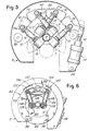
- the arms 15, 17, 19 and 21 must be capable of being angularly displaced around the respective columns like those indicated by 19A and 21A, so that to draw near and move away the rollers respect to the pole axis (when the apparatus has already been mounted) ; the rollers 7, 9, 11 and 13 must be moved away as shown with dotted line in Fig. 3 in order to fit the apparatus on the pole whatever its diameter may be, and must be urged towards the pole axis and then the ones towards the others to engage with some pressure and some friction the pole wall at points more or less equidistant one from the other along each of the two contacting circumferences.
- the single columns, like the ones indicated by 19A and 21A, of arms 15, 21, 17 and 19 are kinematically matched one to the other in order to rotate each in opposite direction to those of the adjacent columns, and this is operated by pairs of sector gears 54, 56, 58, 60, 62, 64, being the sectors 56, 58 and, respectively, the sectors 60, 62, solid one to the other.
- the set of sectors 54 to 64 is operated starting from sector 54 by a pneumatically or fluid-operated piston-cylinder system, indicated by 66 and articulated at 68 to the casing 3 as well as to a radial arm of sector 54.
- the cylinder-piston system 66 when lengthening, causes the rollers 7 and 13 to open apart, and when getting shorter, forces the rollers against the pole whatever its diameter may be.
- the apparatus may be mounted for displacements along even non- cylindrical poles, provided a relatively broad resting surface for the assembly of the eight moving rollers is obtained.
- the jack 66 provides an adjustable and uniform pressure of the rollers on the pole surface.
- the apparatus described herein-before in its parts which provide for its displacement along the pole, is designed for performing brush or equivalent cleanings of the pole and the painting of the same.
- Figs. 1 and 2 the apparatus is illustrated ready for painting.
- Figs. 6 and 7 and in the modified embodiment of Fig. 8 the apparatus is illustrated equipped for brush-operated cleaning.
- the structure 1, 3 carries in its upper part, columns 76 which have, in their upper end, guide rollers 78 in the form of ball bearings or other, able to cooperate with a race 80 having an internal throat formed in a carrousel arrangement 82.
- This arrangement is made up of a ring with a part 84 articulated at 86 and which can be engaged with a latch 88 at the opposite part ; in this way it is possible to complete the ring of the carrousel arrangement through the members 82 and 84 and, thus, to complete the race 80, and the ring can be opened to place the apparatus close to the pole by previous alignment of the aperture created by the lifting of part 84 with the aperture 5 ; the continuity of the race is insured by the hinges 86 and the latch 88.
- a motor 90 on the structure 1, 3 operates a drive wheel 92 to give motion - through friction or a toothing - to the carrousel 82, 84 which is supplied with a corresponding rolling race or a toothed crown for the driving wheel 92. Since, in some circumstances, it is necessary to feed electric power to the rotating arrangement belonging to the carrousel 84, an annular strip for sliding contact, is further provided, being suitably isolated and able to cooperate at least with one sliding contact 96, of coal brush type or equivalent, carried by the structure 1,3.
- a spray gun unit 102 is mounted which may be directly operated by an electric motor or by compressed air suitably generated or supplied, or by a mixed system, except for the possible electrostatic operation with an electrostatic field generated through the pole P to be painted, which pole, in this case, would be obviously metallic.
- two arms 106 are articulated at 104, symmetrically to the gun unit 102, each of which carries at the mobile end a pair of rollers 108 and 110 having vertical axes ; these rollers have more or less adsorbent surfaces.
- the two arms 106 are urged by a spring 111 the one towards the other, in such a way that the rollers 108 will come in contact with an adequately proportioned pressure, with the pole P whatever its diameter may be ; the rollers 110 are in contact with the respective roller 108.
- the two rollers 108 Upon rotation of the carrousel 82, 84 the two rollers 108 roll on the pole surface and give motion to respective rollers 110.
- rollers 108 and 110 make up an efficient, protective curtain for the paint ejected from the unit 102.
- the paint which is not directly thrown on the pole is practically picked up by rollers 108 and 110 on which it is more or less marginally thrown, and these rollers transfer it on the pole to be painted.
- rollers 108, 110 permits also to obtain a regular spreading of the paint on the pole, since the action of ejection and spreading of the paint takes place while the carrousel 82, 84 of the rotating arrangement, rotates during the lowering displacements of the apparatus along the pole ; besides, the rotation and lowering speeds, also depending on the length in vertical direction of rollers 108 and 110, are such as to ensure a repeated action of rollers 108 in each point and thus, at each level of the pole. The risk of the paint dripping or leaking along the pole is also avoided by the repeated action of rollers 108.
- the arms 106 are elastically opened wide apart with respect to each other up to the position shown with dotted line in Fig. 2, at which position these arms are retained by retaining hooks 112.
- hooks 112 The retaining action of said hooks 112 is neutralized, through suitable remote control, the moment the rotation of the motor 50 is reversed to start the lowering of the apparatus while simultaneously giving the start for rotation of carrousel 82, 84 by the actuation of motor 90 and by starting the spout or ejection of the gun ; at the beginning of the movement of arrangement 82, 84 of the carrousel, the hooks 112 move facing at least a suitable cam profile fixed on the structure 1, 3 and are operated by this profile to release arms 106 and thus to cause the matching and the rolling over of rollers 108 against the pole.
- the level of gun 102 and of rollers 108.110 is above the level of the pairs of rollers 7 to 13, which permits to reach and paint even the upper end of the pole since the apparatus is supported on the pole at a certain distance from said end.
- Figs. 6 and 7 show how the apparatus can be equipped with brush means having their axis parallel to the pole, for the cleaning of its surface.
- a structure 120 is applied - in place of the painting system - to which structure two arms 124 are articulated at 122, being urged the one towards the other by a spring 126 likewise as the arms 106 and being capable to be retained by the retaining hooks 112 or equivalent in the same way as the arms 106.
- Each arm 124 carries at the mobile end, a rotating brush 128, which is made to rotate by a chain transmission 130 which takes the motion from a motor 132.
- the brushes rotate relative to the pole in order to work the one in opposite direction to the other on the same pole surface ; the brushes have such a height as to effect a prolonged cleaning action on the pole, which action can be developed either during the lift or the descent of the apparatus along the pole.
- Fig. 8 a further embodiment is shown, in which the arms 136 - similar to those indicated by 124 - carry brushes 138 rotating around axes substantially radial respect to the pole, each brush having advantageously the possibility to be powered independently of the other.
- the apparatus or the operative unit can be replaced, and thus the painting can be performed by sending the apparatus to the upper end of the pole and beginning the painting from top downwards.
- the continuity of the rolling race with the rotating arrangement formed by parts 82, 84, is interrupted by releasing the latch 88, when the apparatus is to be removed by the pole on which it has been applied.
Landscapes
- Spray Control Apparatus (AREA)
- Coating Apparatus (AREA)
- Nozzles (AREA)
- Vessels And Coating Films For Discharge Lamps (AREA)
- Non-Portable Lighting Devices Or Systems Thereof (AREA)
- Physical Or Chemical Processes And Apparatus (AREA)
Claims (8)
Priority Applications (1)
| Application Number | Priority Date | Filing Date | Title |
|---|---|---|---|
| AT85830161T ATE37993T1 (de) | 1984-06-27 | 1985-06-26 | Vorrichtung zum anstreichen von laternenpfaehlen oder dergleichen. |
Applications Claiming Priority (2)
| Application Number | Priority Date | Filing Date | Title |
|---|---|---|---|
| IT8409448A IT1229042B (it) | 1984-06-27 | 1984-06-27 | Dispositivo distributore di vernice per la manutenzione di pali in opera, con proiettore di vernice e rulli distributori |
| IT944884 | 1984-06-27 |
Publications (3)
| Publication Number | Publication Date |
|---|---|
| EP0169177A2 EP0169177A2 (de) | 1986-01-22 |
| EP0169177A3 EP0169177A3 (en) | 1986-10-01 |
| EP0169177B1 true EP0169177B1 (de) | 1988-10-19 |
Family
ID=11130288
Family Applications (1)
| Application Number | Title | Priority Date | Filing Date |
|---|---|---|---|
| EP85830161A Expired EP0169177B1 (de) | 1984-06-27 | 1985-06-26 | Vorrichtung zum Anstreichen von Laternenpfählen oder dergleichen |
Country Status (6)
| Country | Link |
|---|---|
| US (2) | US4677935A (de) |
| EP (1) | EP0169177B1 (de) |
| JP (1) | JPS6164361A (de) |
| AT (1) | ATE37993T1 (de) |
| DE (1) | DE3565636D1 (de) |
| IT (1) | IT1229042B (de) |
Families Citing this family (24)
| Publication number | Priority date | Publication date | Assignee | Title |
|---|---|---|---|---|
| CA1299324C (en) * | 1988-05-04 | 1992-04-28 | Carlos Sinforoso | Oscillating line travel pipe cleaning machine |
| US5458683A (en) * | 1989-07-17 | 1995-10-17 | Crc-Evans Rehabilitation Systems, Inc. | Device for surface cleaning, surface preparation and coating applications |
| US4953496A (en) * | 1989-07-17 | 1990-09-04 | Crc-Evans Pipeline International, Inc. | High pressure water jet cleaner and coating applicator |
| US5520734A (en) * | 1989-07-17 | 1996-05-28 | Crc-Evans Rehabilitation Systems, Inc. | High pressure water jet cleaner and coating applicator |
| US6461231B1 (en) | 1990-08-14 | 2002-10-08 | Crc-Evans Rehabilitation Systems, Inc. | Air abrasive blast line travel machine |
| AT399959B (de) * | 1991-07-09 | 1995-08-25 | Dornstaedter Hermann | Reinigungsgerät für elektrische einrichtungen, wie isolatoren, sicherungen od. dgl. |
| US5197837A (en) * | 1992-02-24 | 1993-03-30 | General Electric Company | Broach tool chip remover |
| US5647906A (en) * | 1992-03-11 | 1997-07-15 | A-Z Terminal Corporation | Pipe cleaning machine |
| GB9929640D0 (en) * | 1999-12-16 | 2000-02-09 | Tecsec Europ Limited | Equippment deployment method and apparatus |
| RU2179081C1 (ru) * | 2000-10-17 | 2002-02-10 | Судаков Александр Васильевич | Проволочная щетка |
| RU2212959C2 (ru) * | 2001-06-19 | 2003-09-27 | Открытое акционерное общество "Татнефть" | Устройство для очистки наружной поверхности трубы |
| US6685157B1 (en) | 2002-03-05 | 2004-02-03 | Valmont Industries, Inc. | Ornamental support pole for a luminaire or the like |
| JP2005058953A (ja) * | 2003-08-19 | 2005-03-10 | Chugoku Electric Power Co Inc:The | 柱材塗装装置 |
| US7200889B2 (en) * | 2004-06-08 | 2007-04-10 | Arun Vohra | Device and process for cleaning electrified contact rail insulators for rail rapid transit systems |
| US20080023123A1 (en) * | 2006-07-31 | 2008-01-31 | Schlumberger Technology Corporation | Automatic elastomer extrusion apparatus and method |
| DE202015000547U1 (de) | 2015-01-27 | 2015-03-12 | Ooo Gazpron Transgaz Sankt Petersburg | Anlage zur Lichtbogen-Plasma-Reinigung der Außenoberfläche von Fernleitungen (Anlage zur Reinigung der Außenoberfläche von Fernleitungen nach dem Lichtbogen-Plasma-Verfahren) |
| CN105013670A (zh) * | 2015-08-23 | 2015-11-04 | 王寿南 | 提高涂刷效率和进行自动干燥的机械 |
| CN105013668A (zh) * | 2015-08-23 | 2015-11-04 | 王寿南 | 一种用于棒材涂刷和干燥的设备 |
| CN105013669A (zh) * | 2015-08-23 | 2015-11-04 | 王寿南 | 提高阳极棒涂刷效率和干燥效率的机械 |
| DE202015009154U1 (de) | 2015-10-21 | 2016-12-08 | OOO Gazprom transgaz Sankt Petersburg | Vorrichtung zur Lichtbogen-Plasma-Oberflächenreinigung von Metallerzeugnissen und eine Einrichtung hierfür |
| DE202016008318U1 (de) | 2016-04-08 | 2017-07-21 | Andrey Senokosov | Maschine zur Plasmareinigung von Rohraußenflächen |
| CN108043657B (zh) * | 2017-12-20 | 2020-09-25 | 砀山县展望罐头食品厂 | 一种旋转升降式树干刷白装置 |
| CN109013192B (zh) * | 2018-08-27 | 2023-09-05 | 海南汉地阳光石油化工有限公司 | 一种可调节密封性的密封装置 |
| CN111644310A (zh) * | 2020-06-01 | 2020-09-11 | 肇庆宏旺金属实业有限公司 | 一种整卷不锈钢表面抗指纹加工装置及方法 |
Family Cites Families (9)
| Publication number | Priority date | Publication date | Assignee | Title |
|---|---|---|---|---|
| GB190106241A (en) * | 1901-03-25 | 1901-04-27 | Isaac Koslowsky | A Process of and Compositions for Protecting Iron Constructions from Incandescence in Case of Fire. |
| US2301165A (en) * | 1940-07-13 | 1942-11-03 | Gardiner Coating Machine Compa | Machine for coating pipe |
| GB659092A (en) * | 1948-09-13 | 1951-10-17 | Leslie Andrew Rundle | Mechanical painting apparatus |
| US2821162A (en) * | 1954-12-09 | 1958-01-28 | Andrew C Robinson | Pole coating apparatus |
| US2858555A (en) * | 1955-06-09 | 1958-11-04 | Medovick George | Self-propelled cleaning or painting device |
| US2998801A (en) * | 1958-06-23 | 1961-09-05 | Kamco Products Inc | Device for painting flagpoles, suspension cables and the like |
| US3116811A (en) * | 1961-04-27 | 1964-01-07 | Clair V Stevenson | Portable cable cleaner and lubricator |
| FR1546499A (fr) * | 1966-05-27 | 1968-11-22 | Dispositif électromécanique pour la peinture et l'entretien des poteaux tubulaires | |
| JPS527874U (de) * | 1975-07-02 | 1977-01-20 |
-
1984
- 1984-06-27 IT IT8409448A patent/IT1229042B/it active
-
1985
- 1985-06-26 AT AT85830161T patent/ATE37993T1/de not_active IP Right Cessation
- 1985-06-26 EP EP85830161A patent/EP0169177B1/de not_active Expired
- 1985-06-26 DE DE8585830161T patent/DE3565636D1/de not_active Expired
- 1985-06-26 US US06/749,288 patent/US4677935A/en not_active Expired - Fee Related
- 1985-06-27 JP JP60139247A patent/JPS6164361A/ja active Pending
-
1987
- 1987-04-02 US US07/034,061 patent/US4771499A/en not_active Expired - Fee Related
Also Published As
| Publication number | Publication date |
|---|---|
| ATE37993T1 (de) | 1988-11-15 |
| EP0169177A3 (en) | 1986-10-01 |
| JPS6164361A (ja) | 1986-04-02 |
| DE3565636D1 (en) | 1988-11-24 |
| IT8409448A0 (it) | 1984-06-27 |
| US4677935A (en) | 1987-07-07 |
| EP0169177A2 (de) | 1986-01-22 |
| US4771499A (en) | 1988-09-20 |
| IT1229042B (it) | 1991-07-17 |
Similar Documents
| Publication | Publication Date | Title |
|---|---|---|
| US4677935A (en) | Paint spreader apparatus for the maintenance of installed poles, with paint ejector and spreading rollers | |
| RU2559504C2 (ru) | Головка для повторного окрашивания крышек скругленной формы | |
| US4075975A (en) | Rotator and coater system for drum shells | |
| US2330880A (en) | Coating machine | |
| CN112031347B (zh) | 建筑墙面自动粉刷机器人及方法 | |
| CN113399150A (zh) | 一种安全头盔喷漆装置 | |
| CN113231228A (zh) | 一种天然气集输管道缓蚀剂涂膜装置及涂膜工艺 | |
| CN110756355A (zh) | 一种木制家具加工用喷蜡装置及其使用方法 | |
| CN219901400U (zh) | 一种电杆打磨刷漆一体化设备 | |
| CN1072114A (zh) | 卧式条状物涂装机 | |
| CN211247108U (zh) | 一种汽车横梁喷漆装置 | |
| CN111729801B (zh) | 一种装修定制家具抽拉把手自动化加工机械及其加工方法 | |
| CN219273397U (zh) | 一种大型钢结构构件的喷涂装置 | |
| CN210935524U (zh) | 一种乳化炸药给料泵用喷漆装置 | |
| CN217648603U (zh) | 一种陶瓷产品省力式内外均匀喷釉装置 | |
| US2519177A (en) | Apparatus for coating cylindrical vessels | |
| CN217856885U (zh) | 一种喷涂车间用自动喷枪 | |
| CN203209243U (zh) | 一种垫圈润滑剂喷涂系统 | |
| JP2012000718A (ja) | 素地調整装置 | |
| US6368417B1 (en) | Tire mold cleaning method and apparatus | |
| CN219024694U (zh) | 一种表面喷涂装置 | |
| CN209953109U (zh) | 一种高适用性的管件内壁涂料喷涂装置 | |
| CN216153419U (zh) | 一种钢瓶打标设备 | |
| CN220599042U (zh) | 一种墙面连续涂装设备 | |
| CN220277347U (zh) | 环形链条式喷漆机构 |
Legal Events
| Date | Code | Title | Description |
|---|---|---|---|
| PUAI | Public reference made under article 153(3) epc to a published international application that has entered the european phase |
Free format text: ORIGINAL CODE: 0009012 |
|
| AK | Designated contracting states |
Designated state(s): AT BE CH DE FR GB LI LU NL SE |
|
| PUAL | Search report despatched |
Free format text: ORIGINAL CODE: 0009013 |
|
| AK | Designated contracting states |
Kind code of ref document: A3 Designated state(s): AT BE CH DE FR GB LI LU NL SE |
|
| 17P | Request for examination filed |
Effective date: 19870108 |
|
| 17Q | First examination report despatched |
Effective date: 19870817 |
|
| GRAA | (expected) grant |
Free format text: ORIGINAL CODE: 0009210 |
|
| AK | Designated contracting states |
Kind code of ref document: B1 Designated state(s): AT BE CH DE FR GB LI LU NL SE |
|
| REF | Corresponds to: |
Ref document number: 37993 Country of ref document: AT Date of ref document: 19881115 Kind code of ref document: T |
|
| REF | Corresponds to: |
Ref document number: 3565636 Country of ref document: DE Date of ref document: 19881124 |
|
| ET | Fr: translation filed | ||
| PG25 | Lapsed in a contracting state [announced via postgrant information from national office to epo] |
Ref country code: LU Free format text: LAPSE BECAUSE OF NON-PAYMENT OF DUE FEES Effective date: 19890630 |
|
| PLBE | No opposition filed within time limit |
Free format text: ORIGINAL CODE: 0009261 |
|
| STAA | Information on the status of an ep patent application or granted ep patent |
Free format text: STATUS: NO OPPOSITION FILED WITHIN TIME LIMIT |
|
| 26N | No opposition filed | ||
| PGFP | Annual fee paid to national office [announced via postgrant information from national office to epo] |
Ref country code: LU Payment date: 19900523 Year of fee payment: 6 |
|
| PGFP | Annual fee paid to national office [announced via postgrant information from national office to epo] |
Ref country code: AT Payment date: 19900528 Year of fee payment: 6 |
|
| PGFP | Annual fee paid to national office [announced via postgrant information from national office to epo] |
Ref country code: SE Payment date: 19900614 Year of fee payment: 6 |
|
| PGFP | Annual fee paid to national office [announced via postgrant information from national office to epo] |
Ref country code: GB Payment date: 19900615 Year of fee payment: 6 |
|
| PGFP | Annual fee paid to national office [announced via postgrant information from national office to epo] |
Ref country code: FR Payment date: 19900625 Year of fee payment: 6 |
|
| PGFP | Annual fee paid to national office [announced via postgrant information from national office to epo] |
Ref country code: CH Payment date: 19900627 Year of fee payment: 6 |
|
| PGFP | Annual fee paid to national office [announced via postgrant information from national office to epo] |
Ref country code: NL Payment date: 19900630 Year of fee payment: 6 |
|
| PGFP | Annual fee paid to national office [announced via postgrant information from national office to epo] |
Ref country code: BE Payment date: 19900712 Year of fee payment: 6 |
|
| PGFP | Annual fee paid to national office [announced via postgrant information from national office to epo] |
Ref country code: DE Payment date: 19900822 Year of fee payment: 6 |
|
| PG25 | Lapsed in a contracting state [announced via postgrant information from national office to epo] |
Ref country code: GB Effective date: 19910626 Ref country code: AT Effective date: 19910626 |
|
| PG25 | Lapsed in a contracting state [announced via postgrant information from national office to epo] |
Ref country code: SE Effective date: 19910627 |
|
| PG25 | Lapsed in a contracting state [announced via postgrant information from national office to epo] |
Ref country code: LI Effective date: 19910630 Ref country code: CH Effective date: 19910630 Ref country code: BE Effective date: 19910630 |
|
| BERE | Be: lapsed |
Owner name: SIVEP DI MENICONI GIORGIO E C. S.A.S. Effective date: 19910630 |
|
| PG25 | Lapsed in a contracting state [announced via postgrant information from national office to epo] |
Ref country code: NL Effective date: 19920101 |
|
| NLV4 | Nl: lapsed or anulled due to non-payment of the annual fee | ||
| GBPC | Gb: european patent ceased through non-payment of renewal fee | ||
| PG25 | Lapsed in a contracting state [announced via postgrant information from national office to epo] |
Ref country code: FR Effective date: 19920228 |
|
| REG | Reference to a national code |
Ref country code: CH Ref legal event code: PL |
|
| PG25 | Lapsed in a contracting state [announced via postgrant information from national office to epo] |
Ref country code: DE Effective date: 19920401 |
|
| REG | Reference to a national code |
Ref country code: FR Ref legal event code: ST |
|
| EUG | Se: european patent has lapsed |
Ref document number: 85830161.7 Effective date: 19920109 |