EP0169314A2 - Machine d'application de manchons d'identification - Google Patents
Machine d'application de manchons d'identification Download PDFInfo
- Publication number
- EP0169314A2 EP0169314A2 EP85104749A EP85104749A EP0169314A2 EP 0169314 A2 EP0169314 A2 EP 0169314A2 EP 85104749 A EP85104749 A EP 85104749A EP 85104749 A EP85104749 A EP 85104749A EP 0169314 A2 EP0169314 A2 EP 0169314A2
- Authority
- EP
- European Patent Office
- Prior art keywords
- sleeve
- marker
- strip
- actuating
- marker sleeve
- Prior art date
- Legal status (The legal status is an assumption and is not a legal conclusion. Google has not performed a legal analysis and makes no representation as to the accuracy of the status listed.)
- Withdrawn
Links
- 239000003550 marker Substances 0.000 title claims abstract description 127
- 238000003780 insertion Methods 0.000 claims description 7
- 230000037431 insertion Effects 0.000 claims description 7
- 230000000717 retained effect Effects 0.000 claims description 6
- 230000007935 neutral effect Effects 0.000 claims description 4
- 230000003213 activating effect Effects 0.000 claims description 2
- 230000001351 cycling effect Effects 0.000 claims description 2
- 238000000034 method Methods 0.000 description 30
- 230000008569 process Effects 0.000 description 30
- 239000000835 fiber Substances 0.000 description 13
- 230000007246 mechanism Effects 0.000 description 10
- 230000002441 reversible effect Effects 0.000 description 4
- 125000006850 spacer group Chemical group 0.000 description 4
- 239000000463 material Substances 0.000 description 3
- 230000009471 action Effects 0.000 description 2
- 238000010276 construction Methods 0.000 description 2
- 230000000694 effects Effects 0.000 description 2
- 238000012986 modification Methods 0.000 description 2
- 230000004048 modification Effects 0.000 description 2
- NIXOWILDQLNWCW-UHFFFAOYSA-M Acrylate Chemical compound [O-]C(=O)C=C NIXOWILDQLNWCW-UHFFFAOYSA-M 0.000 description 1
- JOYRKODLDBILNP-UHFFFAOYSA-N Ethyl urethane Chemical compound CCOC(N)=O JOYRKODLDBILNP-UHFFFAOYSA-N 0.000 description 1
- 229920006266 Vinyl film Polymers 0.000 description 1
- 230000003466 anti-cipated effect Effects 0.000 description 1
- 230000000712 assembly Effects 0.000 description 1
- 238000000429 assembly Methods 0.000 description 1
- 230000000994 depressogenic effect Effects 0.000 description 1
- 230000005611 electricity Effects 0.000 description 1
- 229920002457 flexible plastic Polymers 0.000 description 1
- 229920006284 nylon film Polymers 0.000 description 1
- 239000000123 paper Substances 0.000 description 1
- 239000002985 plastic film Substances 0.000 description 1
- 229920006267 polyester film Polymers 0.000 description 1
- 229920000098 polyolefin Polymers 0.000 description 1
- 230000000452 restraining effect Effects 0.000 description 1
- 239000005060 rubber Substances 0.000 description 1
- 238000000926 separation method Methods 0.000 description 1
- 229920001169 thermoplastic Polymers 0.000 description 1
- 239000004416 thermosoftening plastic Substances 0.000 description 1
- 238000011144 upstream manufacturing Methods 0.000 description 1
- 239000002699 waste material Substances 0.000 description 1
Images


Classifications
-
- H—ELECTRICITY
- H01—ELECTRIC ELEMENTS
- H01B—CABLES; CONDUCTORS; INSULATORS; SELECTION OF MATERIALS FOR THEIR CONDUCTIVE, INSULATING OR DIELECTRIC PROPERTIES
- H01B13/00—Apparatus or processes specially adapted for manufacturing conductors or cables
- H01B13/34—Apparatus or processes specially adapted for manufacturing conductors or cables for marking conductors or cables
- H01B13/344—Apparatus or processes specially adapted for manufacturing conductors or cables for marking conductors or cables by applying sleeves, ferrules, tags, clips, labels or short length strips
-
- Y—GENERAL TAGGING OF NEW TECHNOLOGICAL DEVELOPMENTS; GENERAL TAGGING OF CROSS-SECTIONAL TECHNOLOGIES SPANNING OVER SEVERAL SECTIONS OF THE IPC; TECHNICAL SUBJECTS COVERED BY FORMER USPC CROSS-REFERENCE ART COLLECTIONS [XRACs] AND DIGESTS
- Y10—TECHNICAL SUBJECTS COVERED BY FORMER USPC
- Y10T—TECHNICAL SUBJECTS COVERED BY FORMER US CLASSIFICATION
- Y10T29/00—Metal working
- Y10T29/51—Plural diverse manufacturing apparatus including means for metal shaping or assembling
- Y10T29/5186—Covering
-
- Y—GENERAL TAGGING OF NEW TECHNOLOGICAL DEVELOPMENTS; GENERAL TAGGING OF CROSS-SECTIONAL TECHNOLOGIES SPANNING OVER SEVERAL SECTIONS OF THE IPC; TECHNICAL SUBJECTS COVERED BY FORMER USPC CROSS-REFERENCE ART COLLECTIONS [XRACs] AND DIGESTS
- Y10—TECHNICAL SUBJECTS COVERED BY FORMER USPC
- Y10T—TECHNICAL SUBJECTS COVERED BY FORMER US CLASSIFICATION
- Y10T29/00—Metal working
- Y10T29/51—Plural diverse manufacturing apparatus including means for metal shaping or assembling
- Y10T29/5191—Assembly
-
- Y—GENERAL TAGGING OF NEW TECHNOLOGICAL DEVELOPMENTS; GENERAL TAGGING OF CROSS-SECTIONAL TECHNOLOGIES SPANNING OVER SEVERAL SECTIONS OF THE IPC; TECHNICAL SUBJECTS COVERED BY FORMER USPC CROSS-REFERENCE ART COLLECTIONS [XRACs] AND DIGESTS
- Y10—TECHNICAL SUBJECTS COVERED BY FORMER USPC
- Y10T—TECHNICAL SUBJECTS COVERED BY FORMER US CLASSIFICATION
- Y10T29/00—Metal working
- Y10T29/51—Plural diverse manufacturing apparatus including means for metal shaping or assembling
- Y10T29/5193—Electrical connector or terminal
-
- Y—GENERAL TAGGING OF NEW TECHNOLOGICAL DEVELOPMENTS; GENERAL TAGGING OF CROSS-SECTIONAL TECHNOLOGIES SPANNING OVER SEVERAL SECTIONS OF THE IPC; TECHNICAL SUBJECTS COVERED BY FORMER USPC CROSS-REFERENCE ART COLLECTIONS [XRACs] AND DIGESTS
- Y10—TECHNICAL SUBJECTS COVERED BY FORMER USPC
- Y10T—TECHNICAL SUBJECTS COVERED BY FORMER US CLASSIFICATION
- Y10T29/00—Metal working
- Y10T29/53—Means to assemble or disassemble
- Y10T29/53657—Means to assemble or disassemble to apply or remove a resilient article [e.g., tube, sleeve, etc.]
Definitions
- the present invention relates to a machine for handling a web of marker sleeves of flexible plastic film material to enable an operator to rapidly apply the marker sleeves to an object to be identified, such as an electrical wire or similar tubular article.
- a flexible web of marker sleeves such as described above can be easily manipulated by hand for manual detachment of a marker sleeve from the assembly for application to an object as an identification device.
- an identification device there are a number of users who must identify a large number of objects and therefore have need of a machine for application of the subject marker sleeves, which will also facilitate high speed application of the sleeves.
- No suitable machine is available to our knowledge, and we have therefore developed the marker sleeve applicator machine of the present invention to satisfy this need.
- the marker sleeve applicator machine of the present invention comprises an.application station including sleeve engagement means for receiving a marker sleeve, severing means for removing an endmost marker sleeve from a strip thereof, and opening means for opening a flat marker sleeve; and means for feeding the endmost marker sleeve of a strip thereof to the sleeve engagement means.
- the operator can insert a wire, or other article, into the open sleeve and withdraw the wire from the application station bearing the sleeve marker as an identification device.
- the machine as described below is adapted to handle a web having a single strip of marker sleeves as described above, or a web having a plurality of strips of marker sleeves. In the latter instance, the machine is designed to separately index each of a plurality of strips of marker sleeves to the application station for the sequential removal of the endmost sleeve marker from each strip for application to a wire.
- the machine of this invention was developed for the purpose of removing individual marker sleeves from a web of marker sleeves, and opening each marker sleeve so that an operator can insert an element such as a wire into the open sleeve for identification of the element.
- the ensuing description is divided into several parts to facilitate an understanding of the machine and its operation.
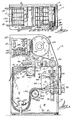
- the marker sleeve applicator machine of this invention is identified by the general reference numeral 1.
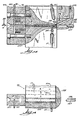
- the support structure or framework of the machine best illustrated in Figs. 1, 2 and 3, comprises a base 2 and a vertical wall 3 extending upwardly from the base.
- the surface of the wall 3 towards the viewer in Fig. 1 will be referred to as the front of the wall; all of the elements a person faces when operating the machine extend from the front of the wall 3.
- Some of the drive mechanisms for the operating elements are supported from the back of the wall 3, as will be explained below, but have been omitted from several of the drawings for the sake of clarity.
- a vertical stiffening web 4 is connected between the vertical wall 3 and base 2.
- a short end wall 5 extends rearwardly from the right side of the wall 3.
- the end wall 5 is also shown in dashed line in Fig. 1 and part of it is illustrated in Fig. 12.
- Fig. 4 illustrates a type of web of sleeve markers which can be applied with the machine 1.
- the web 10 comprises an assembly of sleeve markers formed of a base film 11 and four top films 12, 13, 14 and 15 joined together along spaced parallel transverse seams 16.
- This structure defines a plurality of individual flat tubular sleeve markers 17, each having opposed open ends and closed sides.
- a separable line means 18, such as a row of slits, score lines, perforations etc. extends longitudinally of the web between each of the top films 12-15, which are slightly spaced from one another; also, a similar separable line means 18 is formed in each marginal portion 19 of the base film 11 closely adjacent the outer top films 12 and 15 of the assembly.
- Individual sleeve markers 17 are detachable from the web along a transverse separable line means 16a (not shown in Fig. 4, but see Fig. 16) formed centrally along each transverse seam 16.
- An individual sleeve marker 17 is illustrated in Fig. 4, after having been detached from the web 10.
- the web 10 of sleeve markers is formed of flexible sheet material, most generally flexible thermoplastic films such as polyester films, acrylate films, vinyl films, nylon films and polyolefin films; one or more of the webs may be of paper, and the base and top films may be of the same or dissimilar materials.
- flexible thermoplastic films such as polyester films, acrylate films, vinyl films, nylon films and polyolefin films; one or more of the webs may be of paper, and the base and top films may be of the same or dissimilar materials.
- a web 10 of sleeve markers is led from a supply roll supported on the machine and slit along the separable line means 18 into four strips A, B, C and D, each strip consisting of a top film 12, 13, 14 or 15 and an underlying length of the bottom film 11 between an adjacent pair of separable line means 18.
- the marginal portions 19 of the bottom film are discarded as waste material.
- the four strips of sleeve markers are overlapped or stacked upon one another, and each strip is thereafter individually fed to an indexing station.
- Strip A is indexed to an application station and the endmost sleeve marker 17 thereof is separated from the strip along a transverse separable line means 16a and opened, after which a wire or similar article to be marked is inserted into the open sleeve.
- Fig. 5 illustrates a sleeve marker 17 applied to a wire 6.
- the strip B is indexed to the application station and its endmost sleeve marker 17 separated from the strip for application to a wire.
- Strips C and D will thereafter be indexed to an application station for the same operations, and the sequence will be repeated after removal of the endmost sleeve marker from strip D.
- a web 10 of marker sleeves is wound into a roll carried on a cardboard core and retained by end plate 20 which is supported on a shaft 21 extending from the vertical wall 3 and cantilevered from the front of the wall.
- a flexible strap 22 is secured at its one end to a pin 23 attached to the front of the wall 3 near one side of the roll of web 10.
- the strap 22 rests against and extends partly around the roll of web 10 and is weighted at its free end 24.
- the strap 22 thus acts as a brake to apply a slight restraining force against the roll of web 10 for better control of its unwinding from the roll.
- the web 10 is led about a rotatable guide roll 25 journaled in the wall 3 and then past a slitting station indicated by the general reference numeral 30.
- the guide roll 25 is journaled in bearing 26 about a shaft 27 extending from the wall 3, there being a similar bearing 26 not shown at the end of the shaft nearest the wall.
- the guide roll 25 is preferably axially adjustable for about 3 to 6mm (1/8 to 1/4 inch) by means of knob 28 threaded onto the shaft 27, the guide roll being spring-loaded by a spring not shown, for the reason explained below.
- the web 10 passes between a rod 31 extending from the front of wall 3 and a set of spaced cutting knives 32.
- the knives 32 are secured in a knife holder 33 mounted on a shaft 34 (Fig. 2) extending from the front of wall 3 which has a knob 35 at its outer end.
- the knob 35 By turning the knob 35, the knife holder 33 can be rotated between the cutting position shown in full line in Fig. 1 and the raised position shown in dashed line.
- the knife holder is in its raised position to allow the web to be passed through the cutting station, after which the knife holder 33 is rotated to its cutting position so that the knives can slit the web.
- each knife 32 for each longitudinal separable line means 18 of the web 10, with each knife positioned to slit the web along a line 18.
- the knives 32 are secured to the holder 33 by means of a rod 36 and are held in slots 37 defined in the holder.
- the slots 37 are slightly wider than the knives 32 so that the tips of the knives can float approximately lmm (1/32 inch), which allows the knives to better follow a separable line means 18.
- the holder may be constructed so that the knives can be placed at various positions along its length to accommodate webs 10 with various spacing between the lines 18.
- the guide roll 25 is preferably axially adjustable relative to the front of the wall 3. The purpose of this adjustment is to permit alignment of the web 10 relative to the cutting station 30 so that the longitudinal separable line means 18 of the web can be accurately positioned along the knives 32.
- the web 10 After leaving the slitting station 30, the web 10, now slit into a plurality of strips A, B, C, and D of sleeve markers, is led through a web feed station identified by the general reference numeral 40.
- a support plate 41 is spaced from the vertical wall 3 and secured thereto by means of a set of spacer bolts 42.
- a rubber covered drive roll 43 is journaled at its outer end in the support plate 41 and connected at its inner end to a drive motor 44 (Fig. 3).
- a pressure roller 45 is journaled between the plate 41 and the vertical wall 3 and may be cammed into and out of contact with the drive roller 43 by means of arm 46.
- the strips A, B, C, and D of sleeve markers from the web 10 are each individually led over guide rods 50, each rod 50 extending forwardly from the vertical wall 3 of the machine. As shown in Fig. 1, the marginal portions 19 of the web 10 are both led over the uppermost guide rod 50 and these portions are discarded as scrap.
- There may be a plurality of guide rods 50 so that the machine can handle webs 10 having more than four rows of sleeve markers.
- the guide rods are preferably arranged along an angled row as shown in Fig. 1 to facilitate proper guiding of the strips A-D.
- the strips A, B, C and D of sleeve markers are overlapped or stacked upon one another and formed into a loop 51 near the base 2 of the machine, and then led upwardly about a strip guide post 52.
- the guide post 52 is a hollow tube secured to the front of the wall 3 by means of bolt 53 extending through a closed end wall 54 of the guide post.
- a shaft collar 55 is attached near the outer end of the guide post 52 and is adjustable along the post 52 so that various widths of strips of sleeve markers can be accommodated.
- the strips A-D are stacked upon one another.
- a limit switch 56 is secured to the front of the wall 3 of the machine and includes an actuating arm : 7.
- the switch is located near the loop 51 of the strips A-D prior to the passage of the strips over the guide post 52.
- the actuating arm 57 is gradually raised; when the arm 57 reaches its uppermost position as illustrated in Fig. 1 with respect to the strip depicted in dashed line, the limit switch 56 is activated so as to supply power for a selected period of time to the drive motor 44.
- drive motor 44 is thus actuated, drive roller 43 rotates to feed more web 10 and reform the loop 51 in the overlapped strips.
- the loop 51 passes between a pair of spaced vertical guide rods 58 and 59, see especially Fig. 3, which extend upwardly from the base 2 of the machine.
- the rear guide rod 58 is fixed, but the forward guide rod 59 is movable so that the space between the two guide rods can be adjusted to accommodate strips of sleeve markers of various widths.
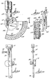
- the strips A-D are led to an indexing means indicated by the general reference numeral 60; as illustrated in dashed line in Fig. 1, the strips A-D are individually fed to feed rollers 61 carried in an indexing head 62, there being one pair of feed rollers 61 for each strip.
- the indexing means 60 of the machine 1 is illustrated as comprising an indexing head 62 formed of a rear plate 63 and a forward plate 64 which is spaced from the rear plate 63 a distance sufficient to accommodate strips of sleeve markers and secured to the plate 63 by means of spacers 65.
- the spacers are arranged in pairs as best shown in Fig. 7, and one spacer 65 of each pair is spaced apart from the other a distance sufficient to allow a strip A-D to pass therethrough.
- a drive shaft 66 extends from the rear plate of the indexing head 62 through the wall 3 of the machine to project from the rear of the wall.
- Pinion gear 67 is secured to a central section of the shaft 66 and ratchet gear 68 is secured to the shaft 66 near its rearmost end.
- a rack 69 engages the teeth of the pinion gear 67 and is driven by a double-acting pneumatic cylinder 70.
- the cylinder 70 is supplied with pressurized air through a line not shown and the cylinder is under constant pressure tending drive the rack upwards to rotate gear 67 clockwise as viewed in Fig. 7. This is the normal direction of movement of the rack, and it can also be driven in the reverse direction by the cylinder 70.
- a reciprocal pawl 71 that engages a notch between the teeth of the ratchet gear 68.
- the pawl 71 is caused to reciprocate by double-acting pneumatic cylinder 72 which also is supplied with pressurized air from a source not shown.
- the indexing head 62 is rotatably supported in the wall 3 along the shaft 66.
- a frame 73 is attached to the rear of the wall 3 and supports the pneumatic cylinders 70 and 72; the pawl 71 and rack 69 extend through the upper and lower horizontal elements of the frame 73.
- the cylinder 70 is constantly under pressure and thus constantly seeks to move the rack upwardly in its normal direction to drive the pinion 67 in a clockwise direction as viewed in Fig. 7, i.e. when viewed from the front of the machine.
- the pawl 71 engages a notch between the teeth of the ratchet gear 68 to prevent rotation of the indexing head 62.
- the rack is allowed to drive the pinion and rotate the indexing head 62 a selected amount.
- the pawl is lifted for a predetermined amount of time so as to permit such rotation of the indexing head.
- each strip A, B, C and D of marker sleeves is lead to a pair of feed rollers 61 supported in the indexing head 62.
- the indexing head is designed to sequentially position each strip alongside a sleeve application station 90.
- Strip B is shown in Fig. 1 indexed at the application station 90, ready to be fed to the application station for removal of the endmost marker sleeve from the strip and the application of the sleeve about an object.
- the indexing head 62 is actuated to position strip C at the application station 90 and then strip D, after which the indexing head is actuated to return strip A to the application station and repeat the cycle by sequentially indexing the four strips A-D to the application station.
- the feeding of the strips to the application station is described in the next part.
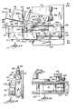
- the mechanism for feeding a strip of sleeve markers through the indexing head to the application station 90 includes a lever 75 pivoted along a pin 76 at its lower end, with its upper end supported in a guide channel 77.
- the pivot pin 76 and guide channel 77 are both attached to the vertical wall 3 of the machine, as explained in the next paragraph.
- the lever 75 is pivoted about the pin 76 by double-acting pneumatic cylinder 78.
- a motor 79 is attached to the lever 75 along a central section thereof and includes a drive roller 80 which is located alongside the application station 90.
- Fig. 1 shows the pivot pin 76 and guide channel 77 attached to the front of the wall 3 of the machine at either end of the lever 75.
- the motor 79 fits within an aperture 81 in the wall 3 and the cylinder 78 fits within an aperture 82 in the wall; the motor 79 extends beyond the rear of the wall.
- Fig. 1 illustrates the attachment to the front of the wall 3 of the end of pneumatic cylinder 78 that is opposite from the end secured to the lever 75.
- one feed roller 61 of each pair has a drive pinion 83 which extends rearwardly from the rear plate 63 of the indexing head 62.
- the feed roller 61 carrying the pinion 83 has a centrally located friction ring 84 which engages a strip of sleeve markers such as shown in connection with the strip D in Fig. 11.
- the lever 75 is pivotable between a drive position illustrated in full line in Fig. 1 and a neutral position shown in dashed line in Fig. 1 by means of the pneumatic cylinder 78.
- the drive motor 79 which may be an electric motor, is operated continuously so that the drive roller 80 is constantly rotating.
- the rotating drive roller 80 (referring now to Fig. 11) engages a drive pinion 83 as indicated by the dashed line to thereby rotate a feed roller 61; this action causes the friction ring 84 to engage a strip of marker sleeves and feed it to the application station 90.
- the lever 75 is in its drive position until a photocell indicates a marker sleeve is in position for application to a wire as explained in part (11) below.
- the feed condition is illustrated in Fig. 1 with respect to the strip B.
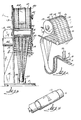
- the sleeve application station 90 isolated from most of the rest of the machine 1 for clarity of descrip.- tion, is illustrated in Figs. 12-19 and includes a pivots- upper jaw 91 and a stationary lower jaw 92 together with their respective associated operating elements.
- the upper jaw 91 includes a front portion 91a bolted to a rear portion 91b that is secured to the end wall 5 of the machine along a pivot pin 93.
- the upper jaw is caused to pivot between a raised or open position shown in in Fig. 12 and a lowered or closed position shown in Fig. 18 by means of a double-acting pneumatic cylinder 94 connected by yoke 95 to the rearmost end of the upper jaw.
- the upper nose piece 97 is attached to the front end of the upper jaw 91.
- the upper nose piece 97 includes a longitudinal semicircular groove 98 opening onto its lower surface which is shown in dashed line in Fig. 12 and in cross section in Fig. 14, the groove 98 having a flared section at its forward portion.
- the lower surface of the upper jaw 91 includes a longitudinal semi-circular groove 99 shown in dashed line in Fig. 12 and in cross section Fig. 15, the grooves 98 and 99 being aligned with one another so as to form a continuous groove, although the groove 98 may be smaller in diameter than the groove 99.
- a fiber optic element 100 extends through the upper nose piece 97 so as to terminate along the groove 98 as shown in Fig. 14.
- Fiber optic element 101 extends through the upper jaw 91 and terminates along the rear section of the groove 99 as best seen in Fig. 12.
- An air channel 102 is defined internally of the upper jaw 91 and communicates with an air channel 103 defined internally of the lower jaw 92 which is positioned to open onto the rearmost section of the groove 99.
- the air channel 102 is connected to a suitable source of pressurized air, not shown, by tube 104.
- a lower jaw nose piece 107 is attached to the front end of the lower jaw 92.
- a longitudinal groove 108 extends along the upper surface of the nose piece 107 that is complimentary to and opens onto the groove 98 of the upper nose piece 97.
- the lower jaw has a longitudinal groove 109 which is complimentary to and faces and opens onto the groove 99 of the upper jaw 92.
- the grooves 99 and 109 combine to define a longitudinal sleeve channel 113 extending across the upper and lower jaws 91 and 92, respectively.
- a fiber optic element 110 extends through the lower nose piece 107 so as to terminate along the groove 108 as shown in Fig. 14 and is arranged in alignment with the fiber optic element 100 of the upper nose piece 97.
- the fiber optic elements 100 and 110 are retained in position in the upper and lower nose pieces respectively by set screws, see Fig. 18, located internally of the nose pieces.
- a fiber optic element 111 is located near the rearmost section of the lower jaw 92 and terminates along the rear section of the groove 109.
- the fiber optic elements 101 and 111 are held in position by means of external set screws 114, from whence they lead inside the lower jaw nose piece and lower jaw respectively to terminate along the grooves 99 and 109.
- a mounting block 115 is secured to the end wall 5 by means of bolts, not shown.
- the lower jaw 92 is attached to the front end 115a of the mounting block so as to be fixed in position.
- the nose pieces 97 and 107 are bolted to the upper and lower jaws respectively, and the upper and lower jaws 91 and 92 are bolted to their respective supporting structure. This allows for interchangeability of the jaws and nose pieces to accommodate marker sleeves of different lengths and diameters and wires of different diameter simply by changing to jaws and nose pieces with appropriate sizes of channels 112 and 113.
- the mounting block 115 also supports a mechanism for severing the endmost marker sleeve from a strip of sleeves and a mechanism for opening a sleeve so as to enable insertion of a wire into the sleeve.
- a pneumatic double acting cylinder 116 is attached to the lower forward section of the mounting block 115 and is supplied with pressurized air from a source not shown through lines 117 and 118. Actuation of the cylinder 116 causes reciprocation of shaft 119 which extends rearwardly from the cylinder. The shaft 119 extends through a urethane bumper block 120 intermediate its ends. The rearmost end of the shaft 119 is attached to a sliding block 121 by means of a cap nut 122.
- a guide shaft 123 is supported at its ends in blocks 124 and 125 attached to the mounting block 115.
- the guide shaft 123 extends through a longitudinal bore formed through the central body portion of the sliding block 121 so that the block 121 can slide along the guide shaft 123 upon actuation of the pneumatic cylinder 116.
- the sliding block 121 includes an upper member 121a that carries two elements: a knife 126 and a rod 127, the knife 126 being nearest the end wall 5 behind rod guide 128 located near the front of the mounting block 115.
- the rod 127 is outboard of the knife and extends through the rod guide 128.
- the knife and rod will both extend or move forward upon operation of the cylinder 116 to drive the shaft 119 in the direction of arrow 129, and retract or move rearward to the position shown in Fig. 12 upon operation of the cylinder 116 to drive the shaft 119 in the direction of arrow 130.
- Air channel 103 extends through the rod guide 128 and exits the guide near the rear of the groove 109. The channel 103 communicates with air channel 102 at its entrance end.
- the rear view of the machine 1 of Fig. 6 shows the pneumatic circuit for operating the various elements described above and the control circuit for controlling the sequence of operations.
- the air pressure is controlled by regulator 145.
- Solenoid valve 142 supplies air through air lines 150 and 151 to cylinder 70 to activate the rack 69.
- Solenoid valve 143 supplies air through air lines 152 and 153 to cylinder 72 to operate pawl 71.
- Solenoid valve 144 supplies air through air lines 154 and 155 to cylinder 78 to pivot lever 75 for feeding of strips to the application station.
- a photoelectric sensor 160 is attached to the end wall 5 and connected to fiber optic elements 100 and 110.
- Photoelectric sensor 161 is attached to the rear of wall 3 and connected to fiber optic elements 101 and 111.
- Electricity through power line 162 is led to terminal strip 163 and utilized to power electric motors 44 and 79, photoelectric sensors 160 and 161, and a programmable control circuit that includes a power supply 170 and programmable controller 171; input/output expanders 172 and 173 also may be used, depending on the input/output capacity of the controller 171.
- the various electrical lines have been omitted from Fig. 6 for clarity, it being understood that suitable wires are connected as required between the various units.
- the programmable controller 171 of the illustrative embodiment is an Omron model Sysmac S6 programmable controller unit available commercially from Omron Electronics, Inc., Schaumburg, Illinois and the input and output cards 172 and 173 are also Omron units.
- Suitable programmable controllers and other units from other manufacturers may also be used for the control circuit of the machine 1, including programmable controllers such as those described in U. S. Patents 4,165,534 and 4,302,820 to which reference may be had for details of the structure and operation of suitable controllers.
- the switch panel 180 includes switches 181-186 identified as follows:
- Switches 182 and 183 are spring loaded switches normally in their AUTO positions, to which they return after being released from their ON positions.
- switch 185 is a spring loaded switch normally in its RUN position, to which it returns after being released from its RESET position.
- a rotary selector 189 for setting the machine for the number of strips of marker sleeves of a particular web 10; in the illustrative embodiment, the selector 189 is set at 4 inasmuch as the specific web 10 shown in the drawings has four strips A-D of marker sleeves after being slit at the cutting station 30.
- the initial step in the operation of the marker sleeve applicator machine 1 is to load the machine with a supply roll of web 10 of sleeve markers.
- the operator installs a roll of the web 10 onto the shaft 21 of the machine, rotates the knife holder 33 to its raised position by means of knob 35, and moves the pressure roller 45 out of contact with the drive roll 43 by rotating the arm 46.
- the web 10 is then threaded around the guide roll 25, over the rod 31 at the slitting station 30 and between the drive roll 43 and pressure roller 45 at the web feed station 40.
- the knob 35 is rotated to position the knife holder 33 and the knives 32 just above the surface of the web 10, and the guide roll 25 is adjusted axially relative to the wall 3 of the machine by rotating knob 28 until the longitudinal separable line means 18 line up with the knives 32 at the slitting station.
- the knob 35 is then rotated further until the knives 32 puncture the web along the separable line means 18 and lightly touch the rod 31, following which the knob 35 is tightened.
- the operator turns the main power switch 181 to its ON position and depresses loop switch 182 to its "ON" position to thereby activate the drive motor 44 so that web 10 will be fed through the web feed station 40.
- each individual strip is fed between a pair of feed rollers 61 of the indexing head 62; preferably, adjacent pairs of feed rollers are threaded in this fashion as shown in Fig. 1 with respect to the four strips therein illustrated, instead of threading alternate pairs of feed rollers.
- Fig. 20 is a generalized flow chart illustrating the manner in which the controller can be programmed to accomplish the requisite feed.
- the main power switch 181 is ON as shown by process block 200
- the position of loop switch 182 is analyzed as indicated by decision block 201. If the loop switch is in its ON position as described above in connection with manual threading of the web 10, the drive motor 44 is activated while the switch is held in the "ON" position to feed the desired length of web 10 as shown by process box 202.
- the loop switch is released from its ON position, it is spring loaded to return to its "AUTO" position.
- the position of the limit switch 56 is analyzed as indicated by decision box 203. If the arm 57 is in its raised position shown in full line in Fig. 1 to activate the limit switch, which occurs when the loop 51 becomes shortened, the drive motor 44 is activated for a selected time, such as 1.5 seconds, to feed further web 10 and reform the loop 51 as shown by process box 204. Conversely, if the limit switch 56 is not activated, the system loops as shown so that the drive motor 44 is not activated, which is its normal condition.
- main power switch 181 ON and pressurized air (at any suitable pressure, 6Kg/sq.cm. (85 psi) having been used in a prototype machine of this invention) being supplied to the manifold 138, the normal condition of the various elements of the machine is as follows: upper jaw 91 is in its raised or open position; the knife 126 and rod 127 are in their rearward or retracted position; the lever 75 is in its neutral position; air supply to the channels 102 and 103 is off; the pawl 71 is in its down position to engage a notch between teeth of the ratchet gear 68; and the cylinder 70 is supplied with air to actuate the rack 69 in position to rotate the gear 67 in a clockwise direction as seen in Fig.
- main power switch 181 ON, a beam of light is established between the fiber optics 100 and 110 at the forward end of entry channel 112 and a beam of light is established between fiber optics 101 and 111 located near the aft end of sleeve channel 113 along the outboard side of the channel (see Figs. 16 and 17).
- Figs. 21A, 21B and 21C are a generalized flow chart illustrating a manner in which the controller 171 can be programmed for the operating cycle.
- cycle reset switch 185 is checked to determine if it has been pressed to its RESET position as shown by decision block 211. If switch 185 has not been pressed to RESET, the cycle loops as illustrated. If switch 185 is in its RESET position after having been pressed to its RESET position, the position of end cycle switch 186 is analyzed as indicated by decision block 212.
- solenoid valve 144 is activated to supply pressurized air to cylinder 78 so as to pivot lever 75 to its drive position, which operation is depicted by process block 213.
- drive motor 79 operates continuously to rotate drive roller 80, feeding a strip of marker sleeve between the upper jaw 91 and lower jaw 92 begins when lever 75 is pivoted to its drive position. Feeding continues until the strip breaks the beam between fiber optics 101 and 111, which occurs after a marker sleeve is positioned across the groove 109 of the lower jaw 92.
- solenoid valve 144 is activated to supply air to reverse cylinder 78 so as to pivot lever 75 to its neutral position to thereby stop further feeding of the strip as depicted by process block 215.
- solenoid valve assembly 139 is activated to supply air to cylinder 94 to move upper jaw 91 to its lower or closed position in contact with lower jaw 92.
- the position of the strip of marker sleeves it this stage of the operating cycle is shown in Fig. 16 with respect to strip A.
- the endmost marker sleeve 17 of strip A is clamped along its closed side edge portions between the upper jaw 91 and lower jaw 92, with its flat tubular body portion across the sleeve channel 113 formed by the grooves 99 and 109 of the upper and lower jaws.
- the transverse separable line means 16a connecting the sleeve 17 to strip A is positioned within a rectangular channel 131 defined by a rectangular groove 132 formed in the upper jaw 91 and a complimentary rectangular groove 133 formed in the lower jaw 92.
- solenoid valve 140 is activated as illustrated by process block 218 to supply a blast of pressurized air through air channel 102 in the upper jaw.
- the air blast flows from air channel 102 through air channel 103 of the rod guide 128 and is directed towards an end of the sleeve 17 so as to partially open the sleeve.
- This condition is illustrated in Fig. 18.
- Air is supplied through channels air 102 and 103 for a preselected time for this purpose, such as the 0.20 seconds shown by process box 218.
- the knife 126 and rod 127 are extended as shown by process block 219.
- the controller activates solenoid valve 141 to supply pressurized air to cylinder 116 to drive the knife 126 and rod 127 forwardly in the direction of arrow 129 of Fig. 12.
- the knife 126 and rod 127 are both in their rearward or retracted position, which is illustrated in Figs. 12, 16, 18 and 19. Referring particularly to Fig. 16, the knife 126 in its rearward or retracted position is behind the strip A and the rectangular channel 131. The rod 127 also is positioned behind the strip A and the sleeve channel 113 formed by the complimentary grooves 99 and 109 of the upper and lower jaws respectively.
- the knife is driven to its extended position in which it enters channel 131 and the rod is driven to its extended position in which it enters the sleeve channel 113, which has two effects: (a) the knife 126 is driven forward so as to remove the endmost .marker sleeve 17 from the strip A along the transverse separable line means 16a, and (b) the rod 127 is driven forward so as to fully enter the open sleeve 17, i.e. the sleeve that has been opened by the air blast through channel 103 as noted above.
- This condition is illustrated in the cross-sectional view of Fig. 17.
- a single marker sleeve 17 is now disposed between the upper and lower jaws at the application station 90 and in an open condition ready for the insertion of a wire to be identified with the sleeve.
- the controller 171 analyzes the condition of the beam between the optics 100 and 110. If the beam is broken (upon insertion of the wire into the entry channel 112) the cycle proceeds to process box 221; if the beam is not broken, the cycle loops as illustrated.
- process block 221 (Fig. 21B)
- the knife 126 and rod 127 are moved to their retracted or rearward position to be withdrawn from the open sleeve so that the wire 6 can be fully inserted into the sleeve channel 113 between the upper jaw 91 and lower jaw 22 and entirely through the sleeve 17 held between the two jaws.
- the controller 171 activates the circuitry to raise the upper jaw 91 as shown by process block 223. This is accomplished by activating solenoid valve assembly 139 to supply pressurized air to cylinder 94 in a direction which will raise the upper jaw 91.
- the operator can remove the wire bearing the marker sleeve from between the jaws 91 and 92; this is done by moving the marker sideways out from between the jaws.
- a short 0.02 second air blast is delivered through the air channel 103 for the purpose of clearing debris from sleeve channel 113 and entry channel 112.
- process block 225 and decision block 226 The next step in the cycle is shown by process block 225 and decision block 226.
- the operator had previously rotated selector switch 189 (Fig. 1) and set it to the number of strips of marker sleeves on the specific web 10 loaded onto the machine 1. This is indicated by the process block 225.
- the controller ascertains the value of "N", the number of strips to which selector switch 189 is set, as indicated by decision block 226. If the selector switch is set at one strip, i.e. the web 10 on the machine has only a single strip of marker sleeves, the system loops as shown by branch 226a to rerun the cycle commencing with decision box 212. On the other hand, if the selector switch 189 is set to a strip number greater than 1, the cycle proceeds through process blocks 227 and 228.
- Process block 227 represents a counter in the programmable controller 171 which acts to count the number of marker sleeves removed and applied to a wire as described above.
- the controller 171 adds "1" to the value of X.
- the controller analyzes and compares the value of X and N and either condition (I) or condition (II) may be present.
- the subsequent strip of marker sleeves has been positioned at the application station, and the cycle loops back upstream of decision box 212 as shown and the endmost marker sleeve 17 of the subsequent strip is fed to the'sleeve channel 113 and removed for application to a wire as described above.
- the operating cycle described above continues to automatically feed strips of marker sleeves sequentially to the application station 90 and remove the endmost , sleeves for application to a wire or other object to be identified with a sleeve.
- the operator has the ability to halt the cycle at any time for whatever reason by pressing the cycle hold switch 184 to its HOLD position; when sleeve application is to be resumed, the hold switch 184 is pressed to its RUN position to resume the cycle at whatever stage it had been stopped.
- the end cycle switch 186 is pressed to its END position before inserting the wire, after which the wire is inserted into the entry channel 112. This operation takes the machine out of its-normal running cycle, and the upper jaw 91 will remain in its raised position after the last sleeve is removed from between the jaws, but the operating cycle will not repeat.
- FIG. 22 A generalized flow chart illustrating this functionality is illustrated in Fig. 22. Many of the process boxes and decision boxes of the flow chart of Fig. 22 are the same as corresponding steps of the flow chart of Fig. 21; they are therefore labeled and numbered the same as in Fig. 21, and their operation will not be repeated at ⁇ this point.
- the sole difference between the flow chart of Fig. 22 and that of Fig. 21 resides in decision box 250.
- the programmable controller 171 analyzes the position of the index switch 183. If the switch is in the ON position, the cycle proceeds in the same manner as the operating cycle of Fig. 21 except that there is no feeding of a strip to the applicator station or severance of the endmost sleeve from the strip.
- This indexing functionality of the equipment enables the operator to cycle the indexing head 62 through its various positions, and may be used, for example, to ensure that the machine is operating properly.
- the index switch 183 is a spring loaded switch which is normally in its AUTO position.
- the indexing head moves one position; thus, if the operator wants to check several positions of the indexing head, the switch must be pushed once for each position to be so checked. Further, the index switch 183 operates only after the end cycle switch 186 has been pressed to its END position, so as to prevent the index switch from affecting the machine during the operating cycle.
- Our new marker sleeve application machine as described hereinabove provides for feeding one or more strips of marker sleeves to an application station, severing the endmost sleeve from each strip at the application station, and then opening the sleeve so that an operator can insert a wire into the sleeve for identification.
- our new machine further includes a control means, which can include a programmable controller, for cycling the machine through the foregoing functions, thereby allowing the operator to rapidly apply marker sleeves to a wire or other suitable article to be marked therewith.
- An indexing means is included in the machine when it is desired that it be capable of handling more than one strip of marker sleeves.
Landscapes
- Engineering & Computer Science (AREA)
- Manufacturing & Machinery (AREA)
- Replacement Of Web Rolls (AREA)
- Labeling Devices (AREA)
- Advancing Webs (AREA)
- Coating Apparatus (AREA)
Applications Claiming Priority (2)
| Application Number | Priority Date | Filing Date | Title |
|---|---|---|---|
| US06/635,340 US4574440A (en) | 1984-07-27 | 1984-07-27 | Marker sleeve applicator machine |
| US635340 | 1984-07-27 |
Publications (2)
| Publication Number | Publication Date |
|---|---|
| EP0169314A2 true EP0169314A2 (fr) | 1986-01-29 |
| EP0169314A3 EP0169314A3 (fr) | 1988-06-22 |
Family
ID=24547392
Family Applications (1)
| Application Number | Title | Priority Date | Filing Date |
|---|---|---|---|
| EP85104749A Withdrawn EP0169314A3 (fr) | 1984-07-27 | 1985-04-19 | Machine d'application de manchons d'identification |
Country Status (4)
| Country | Link |
|---|---|
| US (1) | US4574440A (fr) |
| EP (1) | EP0169314A3 (fr) |
| JP (1) | JPS6147332A (fr) |
| CA (1) | CA1235934A (fr) |
Cited By (3)
| Publication number | Priority date | Publication date | Assignee | Title |
|---|---|---|---|---|
| GB2197292A (en) * | 1986-11-14 | 1988-05-18 | Plessey Co Plc | Marker sleeve applicator tool |
| DE102014211818A1 (de) | 2014-06-20 | 2015-12-24 | Wolfgang Hermann | Verfahren zum Herstellen eines Kabels mit einer flexiblen Hülse, insbesondere einer Markierungshülse, und Kabelmarkiervorrichtung |
| WO2021165307A1 (fr) * | 2020-02-17 | 2021-08-26 | Phoenix Contact Gmbh & Co. Kg | Dispositif d'étiquetage de conducteurs |
Families Citing this family (14)
| Publication number | Priority date | Publication date | Assignee | Title |
|---|---|---|---|---|
| US4655129A (en) * | 1985-10-11 | 1987-04-07 | W. H. Brady Co. | Marker sleeve processing machine |
| JPH071646B2 (ja) * | 1989-12-29 | 1995-01-11 | 株式会社ニチフ端子工業 | 電線端部識別子の装着方法及び装置 |
| JP3119421B2 (ja) * | 1995-02-09 | 2000-12-18 | 矢崎総業株式会社 | 端子圧着機用アプリケータ |
| CA2184462A1 (fr) * | 1995-09-01 | 1997-03-02 | George C. Triantopoulos | Procede et dispositif de marquage de conducteurs |
| US5766705A (en) * | 1995-10-10 | 1998-06-16 | Raychem Corporation | Marker sleeve assembly |
| US5634252A (en) * | 1996-03-26 | 1997-06-03 | Honeywell Inc. | Apparatus for attaching protective tubing to a component |
| US7691462B2 (en) * | 2004-08-17 | 2010-04-06 | Hellermanntyton Corporation | Wire label with carrier |
| US20060040083A1 (en) * | 2004-08-17 | 2006-02-23 | Hellermann Tyton Corporation | Wire label with carrier |
| US10220535B2 (en) | 2011-09-08 | 2019-03-05 | The Boeing Company | Systems and methods of separating tubing sleeves from a tubing holder |
| US10226877B1 (en) * | 2011-09-08 | 2019-03-12 | The Boeing Company | Systems and methods of separating tubing sleeves from a tubing holder |
| US9944422B2 (en) | 2014-04-04 | 2018-04-17 | Brady Worldwide, Inc. | Sleeve applicator machine and related method of operation |
| US9984594B2 (en) | 2014-05-01 | 2018-05-29 | Hellermanntyton Corporation | Wire label with carrier |
| CN107520590B (zh) * | 2017-09-28 | 2023-10-20 | 深圳市捷牛智能装备有限公司 | 智能装管设备及其装管工艺 |
| US10569399B1 (en) | 2017-11-03 | 2020-02-25 | Brady Worldwide, Inc. | Wire sleeve hand application tool |
Family Cites Families (6)
| Publication number | Priority date | Publication date | Assignee | Title |
|---|---|---|---|---|
| US4034450A (en) * | 1975-05-15 | 1977-07-12 | Raychem Corporation | Marker sleeve installation |
| US4144639A (en) * | 1976-12-22 | 1979-03-20 | Hitachi, Ltd. | Apparatus for fitting flexible annular part around an article |
| US4365400A (en) * | 1980-01-23 | 1982-12-28 | Raychem Corporation | Apparatus for installing sleeves on substrates |
| US4488642A (en) * | 1980-07-28 | 1984-12-18 | Raychem Limited | Polymeric articles |
| US4363401A (en) * | 1981-09-28 | 1982-12-14 | W. H. Brady Co. | Sleeve marker assembly |
| US4442939A (en) * | 1982-06-07 | 1984-04-17 | W. H. Brady Co. | Longitudinally-seamed assembly of sleeve markers |
-
1984
- 1984-07-27 US US06/635,340 patent/US4574440A/en not_active Expired - Fee Related
-
1985
- 1985-04-19 EP EP85104749A patent/EP0169314A3/fr not_active Withdrawn
- 1985-05-13 JP JP60101172A patent/JPS6147332A/ja active Pending
- 1985-06-03 CA CA000483008A patent/CA1235934A/fr not_active Expired
Cited By (9)
| Publication number | Priority date | Publication date | Assignee | Title |
|---|---|---|---|---|
| GB2197292A (en) * | 1986-11-14 | 1988-05-18 | Plessey Co Plc | Marker sleeve applicator tool |
| GB2197292B (en) * | 1986-11-14 | 1990-10-03 | Plessey Co Plc | Marker sleeve applicator tool |
| DE102014211818A1 (de) | 2014-06-20 | 2015-12-24 | Wolfgang Hermann | Verfahren zum Herstellen eines Kabels mit einer flexiblen Hülse, insbesondere einer Markierungshülse, und Kabelmarkiervorrichtung |
| DE102014211818B4 (de) | 2014-06-20 | 2018-04-05 | Wolfgang Hermann | Verfahren zum Herstellen eines Kabels mit einer flexiblen Hülse, insbesondere einer Markierungshülse, und Kabelmarkiervorrichtung |
| WO2021165307A1 (fr) * | 2020-02-17 | 2021-08-26 | Phoenix Contact Gmbh & Co. Kg | Dispositif d'étiquetage de conducteurs |
| BE1028061B1 (de) * | 2020-02-17 | 2021-09-14 | Phoenix Contact Gmbh & Co | Vorrichtung zur Leiterkennzeichnung |
| CN115135500A (zh) * | 2020-02-17 | 2022-09-30 | 菲尼克斯电气公司 | 用于标记导体的装置 |
| US11887755B2 (en) | 2020-02-17 | 2024-01-30 | Phoenix Contact Gmbh & Co. Kg | Device for conductor marking |
| CN115135500B (zh) * | 2020-02-17 | 2024-10-18 | 菲尼克斯电气公司 | 用于标记导体的装置 |
Also Published As
| Publication number | Publication date |
|---|---|
| US4574440A (en) | 1986-03-11 |
| JPS6147332A (ja) | 1986-03-07 |
| EP0169314A3 (fr) | 1988-06-22 |
| CA1235934A (fr) | 1988-05-03 |
Similar Documents
| Publication | Publication Date | Title |
|---|---|---|
| US4574440A (en) | Marker sleeve applicator machine | |
| DE2427324C2 (de) | Maschine zum wahlweisen Verarbeiten von Artikelkarten | |
| US4695005A (en) | Coreless winder for strips of pliable material | |
| DE69206181T2 (de) | Kabelführungs- und Vorbereitungsvorrichtung. | |
| EP1359903B1 (fr) | Procede et dispositif pour la production de plaquettes minces a partir d'un film de principes actifs | |
| DE2209435B2 (de) | Vorrichtung zum automatischen Aufrollen von Gewebebahnen bestimmter Länge | |
| CH647401A5 (de) | Verfahren und vorrichtung zur herstellung von reissverschluessen. | |
| DE2809360C3 (de) | Verfahren und Vorrichtung zum Wickeln und Kassettieren eines Filmbandes | |
| US2929136A (en) | Wire length measuring, marking and severing equipment | |
| GB2127445A (en) | Method and apparatus for making screen panels | |
| DE4211858C2 (de) | Einrichtung zum kernlosen Aufwickeln von Flachmaterial | |
| US3446690A (en) | Apparatus for applying pressure-sensitive labels to cylindrical articles | |
| US6547502B1 (en) | Combination plastic spiral forming machine and semi-automatic plastic spiral binding machine | |
| DE2462304A1 (de) | Vorrichtung zum halbautomatischen aufwickeln von bahnfoermigem gut | |
| DE60300670T2 (de) | Methode zum Starten und Anhalten einer Verpackungsmaschine während eines Produktionswechsels | |
| US4766661A (en) | Apparatus for applying a fabric material to a frame | |
| EP0052486B1 (fr) | Appareil pour la fabrication de câbles d'alimentation | |
| EP0263724B1 (fr) | Procédé et appareil pour transférer et empaqueter des sacs en matière thermoplastique | |
| JPS598004B2 (ja) | 配線用ハ−ネス製造装置 | |
| DE60118190T2 (de) | Etikettiervorrichtung zum spenden von auf einem trägerband haftenden etiketten | |
| EP0379344A2 (fr) | Distributeur de feuilles | |
| US3996720A (en) | Yarn cutting and packaging machine | |
| US4856171A (en) | Method for applying a fabric material to a frame | |
| KR20020024489A (ko) | 상품화를 위한 자동 밴드스트링 묶음장치 및 그 방법 | |
| JPH0640446A (ja) | メッシュ袋等の形をした容器のための自動ラベル貼り機 |
Legal Events
| Date | Code | Title | Description |
|---|---|---|---|
| PUAI | Public reference made under article 153(3) epc to a published international application that has entered the european phase |
Free format text: ORIGINAL CODE: 0009012 |
|
| AK | Designated contracting states |
Designated state(s): AT BE CH DE FR GB IT LI LU NL SE |
|
| 17P | Request for examination filed |
Effective date: 19860301 |
|
| PUAL | Search report despatched |
Free format text: ORIGINAL CODE: 0009013 |
|
| AK | Designated contracting states |
Kind code of ref document: A3 Designated state(s): AT BE CH DE FR GB IT LI LU NL SE |
|
| 17Q | First examination report despatched |
Effective date: 19901001 |
|
| STAA | Information on the status of an ep patent application or granted ep patent |
Free format text: STATUS: THE APPLICATION IS DEEMED TO BE WITHDRAWN |
|
| 18D | Application deemed to be withdrawn |
Effective date: 19910212 |
|
| RIN1 | Information on inventor provided before grant (corrected) |
Inventor name: BEHLMER, ROBERT F. Inventor name: WIRTH, GARY J. |