EP0169322A2 - Verfahren und Formwerkzeug zum Herstellen von Formteilen mit grill-, gitter- oder rostartigen Bereichen, wie KFZ-Soft-faces, Spoiler, Bumper, aus einer fliessfähigen Masse - Google Patents
Verfahren und Formwerkzeug zum Herstellen von Formteilen mit grill-, gitter- oder rostartigen Bereichen, wie KFZ-Soft-faces, Spoiler, Bumper, aus einer fliessfähigen Masse Download PDFInfo
- Publication number
- EP0169322A2 EP0169322A2 EP85105891A EP85105891A EP0169322A2 EP 0169322 A2 EP0169322 A2 EP 0169322A2 EP 85105891 A EP85105891 A EP 85105891A EP 85105891 A EP85105891 A EP 85105891A EP 0169322 A2 EP0169322 A2 EP 0169322A2
- Authority
- EP
- European Patent Office
- Prior art keywords
- mold
- contact surfaces
- grill
- areas
- mass
- Prior art date
- Legal status (The legal status is an assumption and is not a legal conclusion. Google has not performed a legal analysis and makes no representation as to the accuracy of the status listed.)
- Granted
Links
Images

Classifications
-
- B—PERFORMING OPERATIONS; TRANSPORTING
- B29—WORKING OF PLASTICS; WORKING OF SUBSTANCES IN A PLASTIC STATE IN GENERAL
- B29C—SHAPING OR JOINING OF PLASTICS; SHAPING OF MATERIAL IN A PLASTIC STATE, NOT OTHERWISE PROVIDED FOR; AFTER-TREATMENT OF THE SHAPED PRODUCTS, e.g. REPAIRING
- B29C33/00—Moulds or cores; Details thereof or accessories therefor
- B29C33/0033—Moulds or cores; Details thereof or accessories therefor constructed for making articles provided with holes
-
- B—PERFORMING OPERATIONS; TRANSPORTING
- B29—WORKING OF PLASTICS; WORKING OF SUBSTANCES IN A PLASTIC STATE IN GENERAL
- B29C—SHAPING OR JOINING OF PLASTICS; SHAPING OF MATERIAL IN A PLASTIC STATE, NOT OTHERWISE PROVIDED FOR; AFTER-TREATMENT OF THE SHAPED PRODUCTS, e.g. REPAIRING
- B29C43/00—Compression moulding, i.e. applying external pressure to flow the moulding material; Apparatus therefor
- B29C43/32—Component parts, details or accessories; Auxiliary operations
- B29C43/36—Moulds for making articles of definite length, i.e. discrete articles
- B29C43/361—Moulds for making articles of definite length, i.e. discrete articles with pressing members independently movable of the parts for opening or closing the mould, e.g. movable pistons
-
- B—PERFORMING OPERATIONS; TRANSPORTING
- B29—WORKING OF PLASTICS; WORKING OF SUBSTANCES IN A PLASTIC STATE IN GENERAL
- B29C—SHAPING OR JOINING OF PLASTICS; SHAPING OF MATERIAL IN A PLASTIC STATE, NOT OTHERWISE PROVIDED FOR; AFTER-TREATMENT OF THE SHAPED PRODUCTS, e.g. REPAIRING
- B29C44/00—Shaping by internal pressure generated in the material, e.g. swelling or foaming ; Producing porous or cellular expanded plastics articles
- B29C44/34—Auxiliary operations
- B29C44/36—Feeding the material to be shaped
- B29C44/38—Feeding the material to be shaped into a closed space, i.e. to make articles of definite length
- B29C44/385—Feeding the material to be shaped into a closed space, i.e. to make articles of definite length using manifolds or channels directing the flow in the mould
-
- B—PERFORMING OPERATIONS; TRANSPORTING
- B29—WORKING OF PLASTICS; WORKING OF SUBSTANCES IN A PLASTIC STATE IN GENERAL
- B29C—SHAPING OR JOINING OF PLASTICS; SHAPING OF MATERIAL IN A PLASTIC STATE, NOT OTHERWISE PROVIDED FOR; AFTER-TREATMENT OF THE SHAPED PRODUCTS, e.g. REPAIRING
- B29C45/00—Injection moulding, i.e. forcing the required volume of moulding material through a nozzle into a closed mould; Apparatus therefor
- B29C45/17—Component parts, details or accessories; Auxiliary operations
- B29C45/46—Means for plasticising or homogenising the moulding material or forcing it into the mould
- B29C45/56—Means for plasticising or homogenising the moulding material or forcing it into the mould using mould parts movable during or after injection, e.g. injection-compression moulding
-
- B—PERFORMING OPERATIONS; TRANSPORTING
- B29—WORKING OF PLASTICS; WORKING OF SUBSTANCES IN A PLASTIC STATE IN GENERAL
- B29C—SHAPING OR JOINING OF PLASTICS; SHAPING OF MATERIAL IN A PLASTIC STATE, NOT OTHERWISE PROVIDED FOR; AFTER-TREATMENT OF THE SHAPED PRODUCTS, e.g. REPAIRING
- B29C43/00—Compression moulding, i.e. applying external pressure to flow the moulding material; Apparatus therefor
- B29C43/02—Compression moulding, i.e. applying external pressure to flow the moulding material; Apparatus therefor of articles of definite length, i.e. discrete articles
- B29C43/021—Compression moulding, i.e. applying external pressure to flow the moulding material; Apparatus therefor of articles of definite length, i.e. discrete articles characterised by the shape of the surface
- B29C2043/023—Compression moulding, i.e. applying external pressure to flow the moulding material; Apparatus therefor of articles of definite length, i.e. discrete articles characterised by the shape of the surface having a plurality of grooves
-
- B—PERFORMING OPERATIONS; TRANSPORTING
- B29—WORKING OF PLASTICS; WORKING OF SUBSTANCES IN A PLASTIC STATE IN GENERAL
- B29C—SHAPING OR JOINING OF PLASTICS; SHAPING OF MATERIAL IN A PLASTIC STATE, NOT OTHERWISE PROVIDED FOR; AFTER-TREATMENT OF THE SHAPED PRODUCTS, e.g. REPAIRING
- B29C43/00—Compression moulding, i.e. applying external pressure to flow the moulding material; Apparatus therefor
- B29C43/32—Component parts, details or accessories; Auxiliary operations
- B29C2043/3272—Component parts, details or accessories; Auxiliary operations driving means
- B29C2043/3283—Component parts, details or accessories; Auxiliary operations driving means for moving moulds or mould parts
-
- B—PERFORMING OPERATIONS; TRANSPORTING
- B29—WORKING OF PLASTICS; WORKING OF SUBSTANCES IN A PLASTIC STATE IN GENERAL
- B29C—SHAPING OR JOINING OF PLASTICS; SHAPING OF MATERIAL IN A PLASTIC STATE, NOT OTHERWISE PROVIDED FOR; AFTER-TREATMENT OF THE SHAPED PRODUCTS, e.g. REPAIRING
- B29C43/00—Compression moulding, i.e. applying external pressure to flow the moulding material; Apparatus therefor
- B29C43/32—Component parts, details or accessories; Auxiliary operations
- B29C43/34—Feeding the material to the mould or the compression means
- B29C2043/3444—Feeding the material to the mould or the compression means using pressurising feeding means located in the mould, e.g. plungers or pistons
-
- B—PERFORMING OPERATIONS; TRANSPORTING
- B29—WORKING OF PLASTICS; WORKING OF SUBSTANCES IN A PLASTIC STATE IN GENERAL
- B29C—SHAPING OR JOINING OF PLASTICS; SHAPING OF MATERIAL IN A PLASTIC STATE, NOT OTHERWISE PROVIDED FOR; AFTER-TREATMENT OF THE SHAPED PRODUCTS, e.g. REPAIRING
- B29C43/00—Compression moulding, i.e. applying external pressure to flow the moulding material; Apparatus therefor
- B29C43/32—Component parts, details or accessories; Auxiliary operations
- B29C43/36—Moulds for making articles of definite length, i.e. discrete articles
- B29C43/361—Moulds for making articles of definite length, i.e. discrete articles with pressing members independently movable of the parts for opening or closing the mould, e.g. movable pistons
- B29C2043/3615—Forming elements, e.g. mandrels or rams or stampers or pistons or plungers or punching devices
-
- B—PERFORMING OPERATIONS; TRANSPORTING
- B29—WORKING OF PLASTICS; WORKING OF SUBSTANCES IN A PLASTIC STATE IN GENERAL
- B29C—SHAPING OR JOINING OF PLASTICS; SHAPING OF MATERIAL IN A PLASTIC STATE, NOT OTHERWISE PROVIDED FOR; AFTER-TREATMENT OF THE SHAPED PRODUCTS, e.g. REPAIRING
- B29C37/00—Component parts, details, accessories or auxiliary operations, not covered by group B29C33/00 or B29C35/00
- B29C37/006—Degassing moulding material or draining off gas during moulding
-
- B—PERFORMING OPERATIONS; TRANSPORTING
- B29—WORKING OF PLASTICS; WORKING OF SUBSTANCES IN A PLASTIC STATE IN GENERAL
- B29L—INDEXING SCHEME ASSOCIATED WITH SUBCLASS B29C, RELATING TO PARTICULAR ARTICLES
- B29L2031/00—Other particular articles
- B29L2031/30—Vehicles, e.g. ships or aircraft, or body parts thereof
- B29L2031/3055—Cars
-
- B—PERFORMING OPERATIONS; TRANSPORTING
- B29—WORKING OF PLASTICS; WORKING OF SUBSTANCES IN A PLASTIC STATE IN GENERAL
- B29L—INDEXING SCHEME ASSOCIATED WITH SUBCLASS B29C, RELATING TO PARTICULAR ARTICLES
- B29L2031/00—Other particular articles
- B29L2031/737—Articles provided with holes, e.g. grids, sieves
-
- Y—GENERAL TAGGING OF NEW TECHNOLOGICAL DEVELOPMENTS; GENERAL TAGGING OF CROSS-SECTIONAL TECHNOLOGIES SPANNING OVER SEVERAL SECTIONS OF THE IPC; TECHNICAL SUBJECTS COVERED BY FORMER USPC CROSS-REFERENCE ART COLLECTIONS [XRACs] AND DIGESTS
- Y10—TECHNICAL SUBJECTS COVERED BY FORMER USPC
- Y10S—TECHNICAL SUBJECTS COVERED BY FORMER USPC CROSS-REFERENCE ART COLLECTIONS [XRACs] AND DIGESTS
- Y10S264/00—Plastic and nonmetallic article shaping or treating: processes
- Y10S264/83—Injection molding of polyolefin-type foam
-
- Y—GENERAL TAGGING OF NEW TECHNOLOGICAL DEVELOPMENTS; GENERAL TAGGING OF CROSS-SECTIONAL TECHNOLOGIES SPANNING OVER SEVERAL SECTIONS OF THE IPC; TECHNICAL SUBJECTS COVERED BY FORMER USPC CROSS-REFERENCE ART COLLECTIONS [XRACs] AND DIGESTS
- Y10—TECHNICAL SUBJECTS COVERED BY FORMER USPC
- Y10S—TECHNICAL SUBJECTS COVERED BY FORMER USPC CROSS-REFERENCE ART COLLECTIONS [XRACs] AND DIGESTS
- Y10S425/00—Plastic article or earthenware shaping or treating: apparatus
- Y10S425/014—Expansible and collapsible
Definitions
- the invention relates to a method and a mold for producing molded parts with grill, grid or rust-like areas, such as automotive soft faces, spoilers, bumpers, wherein a flowable mass, in particular a reaction mixture of reactive flowable components in one Molding corresponding mold cavity of a mold is introduced and this is filled.
- the object is therefore to find a method and a molding tool of the type mentioned at the outset, air pockets being avoided in the production of the said molded parts.
- the flow of the mass in the mold cavity is preferably directed through guide elements into the recesses corresponding to the deepest points of the ribs. In this way the flow path is controlled.
- the guide elements in the form of lips or beads also serve to determine the wall thickness of the ribs.
- the new mold for the production of moldings with grill, grid or rust-like areas, such as automotive soft faces, spoilers, bumpers, is based on a mold cavity corresponding to the mold part to be produced, the two mold halves in those zones of said areas, where the molding should have openings, contact surfaces are provided.
- the plunger can preferably be operated hydraulically by means of a piston which can be acted on from both sides. But it can also be operated pneumatically or mechanically. If necessary, its lifting height can be adjusted by an adjustable stop.
- the feed rate of the stamp can preferably be controlled, if necessary according to a predetermined program, so that when the mass is displaced from the zones between the contact surfaces into the remaining mold cavity, the flow rates are not too high.
- guide elements are provided between the contact surfaces of the stamp, which protrude into the recesses corresponding to the ribs of the molded part and arranged in the other mold half.
- Such guide elements in the form of lips or beads influence the direction of flow, these guide elements simultaneously determining the shape and wall thickness of the ribs of the molded part.
- the mold 1 consists of an upper mold half 2 and a lower mold half 3.
- the two mold halves 2, 3 enclose between them a mold cavity 4, which as a negative corresponds to a soft face 5 for a motor vehicle.
- This soft face 5 has a grill area 6, in which 7 openings 8 are arranged between ribs.
- a sprue 9 widens into a film sprue 10 opening into the mold cavity 4.
- This piston 12 is guided in a hydraulic chamber 13.
- An adjustable stop screw 14 is used to set the desired lifting height.
- the end face of the stamp 11 has contact surfaces 15, which correspond to contact surfaces 16 of the mold half 3.
- Guide elements 17 in the form of lips are arranged between the individual contact surfaces 15 (indicated by dash-dotted lines in FIG. 3). Between The contact surfaces 16 have recesses 18 which correspond to the ribs 7 as a negative. The guide elements 17 point into the recesses 18 and determine the wall thickness of the ribs 7 when the stamp 11 is in its end position.
- the mass flows through between the contact surfaces 15 and 16 (FIG. 1) and fills the recesses 18.
- the plunger 11 is moved down, displacing the mass between them, so that the contact surfaces 15, 16 are pressed against each other, whereby the openings 8 arise.
- the flow front lines indicated in FIGS. 1 and 3 are intended to illustrate the distribution of the reaction mixture, starting from the film gate 10.
- the mold 1 according to FIGS. 1 to 3 is used.
- a reaction mixture which forms semi-hard polyurethane foam is introduced into the mold cavity 4, which has a volume of 4000 cm 3 .
- the filling time is 2.5 seconds.
- the stamp 11 is retracted and the reaction mixture flows over the contact surface 16 and flows around the guide elements 17.
- the mixture supply is interrupted and the stamp 11 presses against the lower mold half 3.
- the displaced reaction mixture now fills the remaining part of the mold cavity 4 that was previously free.
- the molding tool 1 can be opened and the molding 5 can be removed.
- the mold 1 is then closed again, the punch 11 is retracted and a new mold filling process can be initiated. Alternatively, the punch 11 is pressed against the lower mold half 3 after 2.3 seconds while the mixture is being fed.
Landscapes
- Engineering & Computer Science (AREA)
- Mechanical Engineering (AREA)
- Manufacturing & Machinery (AREA)
- Moulds For Moulding Plastics Or The Like (AREA)
- Injection Moulding Of Plastics Or The Like (AREA)
Abstract
Description
- Die Erfindung richtet sich auf ein Verfahren und ein Formwerkzeug zum Herstellen von Formteilen mit grill-, gitter- oder rostartigen Bereichen, wie KFZ-Soft-faces, Spoiler, Bumper, wobei eine fließfähige Masse, insbesondere ein Reaktionsgemisch aus reaktiven fließfähigen Komponenten in einen dem Formteil entsprechenden Formhohlraum eines Formwerkzeuges eingebracht wird und dieser davon ausgefüllt wird.
- Um den Formzeitzyklus zu verringern, geht man heute zu immer schneller aushärtenden Systemen über, wie sie insbesondere mit Polyurethanreaktionsgemischen möglich sind. So müssen beispielsweise bei der Herstellung von Außenteilen für KFZ-Fahrzeuge, wie Front- oder Heckspoiler, die Formwerkzeughohlräume in weniger als 2 Sekunden gefüllt sein. Diese Tatsache führte zu der Regel, einen Grillbereich stets längs der Rippen durchströmen zu lassen. Hierbei werden jedoch die Fließwege aufgrund des asymmetrisch angeordneten Angusses unzumutbar lang und die Dichteverteilung im Formteil unterschiedlich. Bei einer symmetrischen Anordnung des Angusses sind Lufteinschlüsse wegen der dabei auftretenden Zusammenflüsse unvermeidbar. Aber auch bei Spritzgießverfahren mit üblichen Thermoplasten treten beim Füllen der Formwerkzeughohlräume wegen der immer komplizierter geformten Formteile Schwierigkeiten in Form von Lufteinschlüssen als Folge von Zusammenflüssen auf.
- Es besteht also die Aufgabe, ein Verfahren und ein Formwerkzeug der eingangs genannten Art zu finden, wobei bei der Herstellung der besagten Formteile Lufteinschlüsse vermieden werden.
- Gemäß dem neuen Verfahren geschieht dies dadurch, daß im Formhohlraum in den dem Formteil entsprechenden besagten grill-, gitter- oder rostartigen Bereichen die Zonen vorgesehener Durchbrüche zunächst von der Masse überströmt werden und die Masse erst im weiteren Verlauf bzw. nach Ende des Füllvorganges aus diesen Zonen verdrängt wird.
- Auf diese Weise wird eine mit relativ langsamer Geschwindigkeit vorrückende Fließfront erzielt, welche in sich geschlossen ist, so daß keine Lufteinschlüsse möglich sind. Erst gegen Ende des Füllvorganges wird die Masse aus den Zonen vorgesehener Durchbrüche verdrängt. Es versteht sich, daß dabei die Verdrängungsgeschwindigkeit derart zu wählen ist, daß beim Verdrängen der Masse deren Fließfront so langsam fortschreitet, daß ein vollständiges Ausfüllen des Formhohlraumes ohne Lufteinschlüsse möglich ist.
- Vorzugsweise wird der Strom der Masse im Formhohlraum durch Leitelemente in die den tiefsten Stellen der Rippen entsprechenden Ausnehmungen gerichtet. Auf diese Weise wird der Fließweg gesteuert. Die Leitelemente in Form von Lippen oder Wülsten dienen dabei gleichzeitig der Bestimmung der Wandstärke der Rippen.
- Das neue Formwerkzeug zum Herstellen von Formteilen mit grill-, gitter- oder rostartigen Bereichen, wie KFZ-Soft-faces, Spoiler, Bumper, geht aus von einem dem herzustellenden Formteil entsprechenden Formhohlraum, wobei die beiden Formwerkzeughälften in jenen Zonen der besagten Bereiche, wo das Formteil Durchbrüche besitzen soll, Kontaktflächen vorgesehen sind.
- Das Neue ist darin zu sehen, daß in einer der Formwerkzeughälften mindestens ein Teil dieser Kontaktflächen auf einem in Richtung auf die korrespondierenden Kontaktflächen der anderen Formwerkzeughälfte bewegbaren Stempel angeordnet sind, wobei dieser Stempel zu Beginn des Formfüllvorganges eine zurückgezogene Stellung einnimmt, in welcher die Kontaktflächen Abstand voneinander besitzen, und später eine Stellung einnimmt, in welcher die Kontaktflächen aufeinanderliegen.
- Diese Ausgestaltung erlaubt, daß die Materialströme nicht durch die engen Ausnehmungen der Querverbindungen mit hoher Geschwindigkeit hindurchschießen müssen, sondern daß die Kontaktflächen zwischen den Ausnehmungen überflutet werden können, wodurch eine weitaus niedrigere Fließgeschwindigkeit erzielt wird und Zusammenflüsse vermieden werden. Die im Formhohlraum enthaltene Luft kann problemlos entweichen. Der Stempel läßt sich vorzugsweise durch einen doppelseitig beaufschlagbaren Kolben hydraulisch betätigen. Er kann aber auch pneumatisch oder mechanisch betätigbar sein. Gegebenenfalls ist seine Hubhöhe durch einen verstellbaren Anschlag einstellbar. Vorzugsweise ist die Vorschubgeschwindigkeit des Stempels steuerbar, gegebenenfalls nach einem vorgegebenen Programm, damit beim Verdrängen der Masse aus den Zonen zwischen den Kontaktflächen in den restlichen Formhohlraum nicht zu hohe Fließgeschwindigkeiten entstehen.
- Nach einer besonderen Ausführungsform sind zwischen den Kontaktflächen des Stempels Leitelemente vorgesehen, welche in die den Rippen des Formteils entsprechenden, in der anderen Formwerkzeughälfte angeordneten Ausnehmungen hineinragen.
- Durch derartige Leitelemente in Form von Lippen oder Wülsten wird auf die Strömungsrichtung Einfluß genommen, wobei diese Leitelemente gleichzeitig die Form und Wandstärke der besagten Rippen des Formteils festlegen.
- Ein neues Formwerkzeug für die Herstellung eines Soft-face mit Grillbereich ist in der Zeichnung als Beispiel rein schematisch dargestellt und nachstehend näher erläutert. Es zeigen:
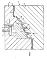
- Fig. 1 den Abriß eines Querschnittes durch das geschlossene Formwerkzeug mit dem Stempel in Füllstellung,
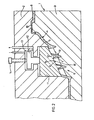
- Fig. 2 den Abriß des Formwerkzeugs gemäß Fig. 1, jedoch mit dem Stempel in Endstellung gegen Ende des Formfüllvorganges und
- Fig. 3 eine Draufsicht auf die untere Formwerkzeughälfte.
- Das Formwerkzeug 1 besteht aus einer oberen Formwerkzeughälfte 2 und einer unteren Formwerkzeughälfte 3. Die beiden Formwerkzeughälften 2, 3 schließen zwischen sich einen Formhohlraum 4 ein, welcher als Negativ einem Soft-face 5 für ein Kraftfahrzeug entspricht. Dieses Soft-face 5 besitzt einen Grillbereich 6, in welchem zwischen Rippen 7 Durchbrüche 8 angeordnet sind. Ein Angußkanal 9 erweitert sich zu einem in den Formhohlraum 4 mündenden Filmanguß 10. In der oberen Formwerkzeughälfte 2 ist ein zur unteren Formwerkzeughälfte 3 hin bewegbarer Stempel 11 angeordnet (in Fig. 3 ist seine Kontur als strichpunktierte Linie angedeutet), welche mittels eines doppelseitig hydraulisch beaufschlagbaren Kolbens 12 betätigbar ist. Dieser Kolben 12 ist in einer Hydraulikkammer 13 geführt. Eine einstellbare Anschlagschraube 14 dient der Einstellung der gewünschten Hubhöhe. Die Stirnfläche des Stempels 11 weist Kontaktflächen 15 auf, welche mit Kontaktflächen 16 der Formwerkzeughälfte 3 korrespondieren. Zwischen den einzelnen Kontaktflächen 15 sind Leitelemente 17 in Form von Lippen angeordnet (in Fig. 3 durch strichpunktierte Linien angedeutet). Zwischen den Kontaktflächen 16 sind Ausnehmungen 18 vorhanden, welche den Rippen 7 als Negativ entsprechen. Die Leitelemente 17 weisen in die Ausnehmungen 18 hinein und bestimmen die Wandstärke der Rippen 7, wenn sich der Stempel 11 in seiner Endstellung befindet. Im zurückgezogenen Zustand des Stempels 11 strömt die Masse zwischen den Kontaktflächen 15 und 16 hindurch (Fig. 1) und füllt dabei die Ausnehmungen 18. Bei fortgeschrittenem Füllvorgang wird der Stempel 11 unter Verdrängung der dazwischen befindlichen Masse herabgefahren, so daß die Kontaktflächen 15, 16 gegeneinander gepreßt werden, wodurch die Durchbrüche 8 entstehen. Die in den Fig. 1 und 3 angedeuteten Fließfrontlinien sollen die Verteilung des Reaktionsgemisches, ausgehend vom Filmanguß 10, verdeutlichen.
- Verwendet wird das Formwerkzeug 1 gemäß Fig. 1 bis 3. Ein halbharten Polyurethanschaumstoff bildendes Reaktionsgemisch wird in den Formhohlraum 4, welcher ein Volumen von 4000 cm3 besitzt, eingebracht. Die Füllzeit beträgt 2,5 Sekunden. Zu Beginn des Formfüllvorganges ist der Stempel 11 zurückgefahren und das Reaktionsgemisch überströmt die Kontaktfläche 16 und umströmt dabei die Leitelemente 17. Nach 2,5 Sekunden, d.h., nachdem das insgesamt benötigte Reaktionsgemisch eingetragen worden ist, wird die Gemischzufuhr unterbrochen und der Stempel 11 preßt sich gegen die untere Formwerkzeughälfte 3. Das verdrängte Reaktionsgemisch füllt nun den restlichen, bisher frei gebliebenen Teil des Formhohlraumes 4 aus. Nach einer Aushärtungszeit von 60 Sekunden kann das Formwerkzeug 1 geöffnet und das Formteil 5 entnommen werden. Das Formwerkzeug 1 wird dann wieder geschlossen, der Stempel 11 zurückgefahren und ein neuer Formfüllvorgang kann eingeleitet werden. Alternativ wird der Stempel 11 noch während der Gemischzufuhr nach 2,3 Sekunden gegen die untere Formwerkzeughälfte 3 gepreßt.
Claims (4)
Applications Claiming Priority (2)
| Application Number | Priority Date | Filing Date | Title |
|---|---|---|---|
| DE19843419824 DE3419824A1 (de) | 1984-05-26 | 1984-05-26 | Verfahren und formwerkzeug zum herstellen von formteilen mit grill-, gitter- oder rostartigen bereichen, wie kfz-soft-faces, spoiler, bumper, aus einer fliessfaehigen masse |
| DE3419824 | 1984-05-26 |
Publications (3)
| Publication Number | Publication Date |
|---|---|
| EP0169322A2 true EP0169322A2 (de) | 1986-01-29 |
| EP0169322A3 EP0169322A3 (en) | 1988-01-07 |
| EP0169322B1 EP0169322B1 (de) | 1990-06-27 |
Family
ID=6237016
Family Applications (1)
| Application Number | Title | Priority Date | Filing Date |
|---|---|---|---|
| EP85105891A Expired - Lifetime EP0169322B1 (de) | 1984-05-26 | 1985-05-14 | Verfahren und Formwerkzeug zum Herstellen von Formteilen mit grill-, gitter- oder rostartigen Bereichen, wie KFZ-Soft-faces, Spoiler, Bumper, aus einer fliessfähigen Masse |
Country Status (3)
| Country | Link |
|---|---|
| US (1) | US4729863A (de) |
| EP (1) | EP0169322B1 (de) |
| DE (2) | DE3419824A1 (de) |
Cited By (1)
| Publication number | Priority date | Publication date | Assignee | Title |
|---|---|---|---|---|
| US7598222B2 (en) * | 2000-01-27 | 2009-10-06 | Eli Lilly And Company | Process for solubilizing glucagon-like peptide 1 compounds |
Families Citing this family (17)
| Publication number | Priority date | Publication date | Assignee | Title |
|---|---|---|---|---|
| CA1291614C (en) * | 1985-12-09 | 1991-11-05 | Sadao Ikeda | Method for the manufacture of molded wooden products |
| US4806094A (en) * | 1986-07-24 | 1989-02-21 | Ex-Cell-O Corporation | Injection molding apparatus for forming film covered inserts for instrument panels |
| EP0295587A3 (de) * | 1987-06-16 | 1989-03-29 | André Klein | Strukturen mit longitudinal nebeneinandergelegten Rippen |
| US5368467A (en) * | 1992-10-06 | 1994-11-29 | Kleyn Die Engravers, Inc. | Molding apparatus for articles having internal undercuts |
| US5456593A (en) * | 1992-10-06 | 1995-10-10 | Kleyn Die Engravers, Inc. | Molding apparatus for articles having internal undercuts |
| WO1994021440A1 (en) * | 1993-03-16 | 1994-09-29 | Signet Industries | Method of molding plastic structural parts |
| US5401355A (en) * | 1993-05-11 | 1995-03-28 | Stiller; Larry B. | Apparatus for manufacturing multiple colored pliable soft trim components using movable dies |
| US5437823A (en) * | 1993-06-23 | 1995-08-01 | Hettinga; Siebolt | Method for molding a plastic article of varied density |
| US5512399A (en) * | 1993-09-21 | 1996-04-30 | Fuji Electric Co., Ltd. | Organic photo sensitive member for electrophotography |
| US5538413A (en) * | 1994-04-29 | 1996-07-23 | University Of Massachusetts Lowell | Apparatus for strengthening weld lines in molded parts |
| US6261662B1 (en) * | 1994-05-02 | 2001-07-17 | Carrier Corporation | Molded element containing a horizontally disposed bore |
| EP0765722A1 (de) * | 1995-09-28 | 1997-04-02 | Siebolt Hettinga | Verfahren zum Kontrollieren der Dicke der Haut eines Kunststoffgegenstandes mit regelter Dichte |
| GB2326373B (en) * | 1998-08-20 | 2000-01-19 | Kurt Mueller | Speaker cone |
| US7426806B2 (en) | 2000-04-20 | 2008-09-23 | Masonite Corporation | Reverse molded panel, method of manufacture, and door manufactured therefrom |
| US7021015B2 (en) | 2000-04-20 | 2006-04-04 | Masonite Corporation | Reverse molded plant-on panel component, method of manufacture, and method of decorating a door therewith |
| WO2001081055A1 (en) | 2000-04-20 | 2001-11-01 | Masonite Corporation | Reverse molded panel |
| US6893599B2 (en) * | 2002-09-09 | 2005-05-17 | Patent Holding Company | Method for making a reinforced, polymeric article in a reaction injection molding system and mold for use therein |
Family Cites Families (14)
| Publication number | Priority date | Publication date | Assignee | Title |
|---|---|---|---|---|
| US2890487A (en) * | 1956-04-03 | 1959-06-16 | Coats & Clark | Spool casting die and core structure |
| US3509603A (en) * | 1967-01-09 | 1970-05-05 | Globe Union Inc | Apparatus for fabricating battery cases |
| US3767742A (en) * | 1967-07-26 | 1973-10-23 | Ici Ltd | Process of injection moulding a hinged article having foam cored members joined by an unfoamed hinge |
| DE1809317B2 (de) * | 1968-11-16 | 1971-02-25 | Verfahren und spritzgiessvorrichtung zum herstellen von kunststoffkoerpern mit hinterschneidungen | |
| US3564660A (en) * | 1968-12-09 | 1971-02-23 | George Darnell | Injection molding machine |
| BE756664A (fr) * | 1969-09-27 | 1971-03-01 | Bayer Ag | Dispositif pour la production de pieces moulees a partir de composants chimiques reagissant rapidement l'un avec l'autre |
| GB1429311A (en) * | 1972-05-03 | 1976-03-24 | Emi Ltd | Moulding of apertured articles |
| GB1358017A (en) * | 1972-08-17 | 1974-06-26 | Richardson Co | Mould assembly and containers produced therefrom |
| US3930780A (en) * | 1973-07-20 | 1976-01-06 | Beatrice Foods Co. | Injection molding apparatus for partitioned containers |
| US3970732A (en) * | 1973-09-26 | 1976-07-20 | Kimball International, Inc. | Method of molding rigid foamed polyurethane articles |
| US4129636A (en) * | 1974-03-20 | 1978-12-12 | Bayer Aktiengesellschaft | Process for providing mixed foamable reactants to a mold |
| CA1072285A (en) * | 1977-01-14 | 1980-02-26 | Edward A. Ruhl | Unitary plastic hinged article and method of making |
| DE3208610A1 (de) * | 1982-03-10 | 1983-09-22 | Raku Kunststoff-Verpackungswerke Gmbh, 7550 Rastatt | Verfahren und vorrichtung zum herstellen eines streusiebes aus kunststoff |
| US4514356A (en) * | 1982-09-15 | 1985-04-30 | Harrison David E | Method of molding a plastic toilet seat hinge connectable bed plate |
-
1984
- 1984-05-26 DE DE19843419824 patent/DE3419824A1/de not_active Withdrawn
-
1985
- 1985-05-14 EP EP85105891A patent/EP0169322B1/de not_active Expired - Lifetime
- 1985-05-14 DE DE8585105891T patent/DE3578398D1/de not_active Expired - Lifetime
- 1985-05-16 US US06/734,711 patent/US4729863A/en not_active Expired - Fee Related
Cited By (1)
| Publication number | Priority date | Publication date | Assignee | Title |
|---|---|---|---|---|
| US7598222B2 (en) * | 2000-01-27 | 2009-10-06 | Eli Lilly And Company | Process for solubilizing glucagon-like peptide 1 compounds |
Also Published As
| Publication number | Publication date |
|---|---|
| US4729863A (en) | 1988-03-08 |
| DE3419824A1 (de) | 1985-11-28 |
| EP0169322B1 (de) | 1990-06-27 |
| EP0169322A3 (en) | 1988-01-07 |
| DE3578398D1 (de) | 1990-08-02 |
Similar Documents
| Publication | Publication Date | Title |
|---|---|---|
| EP0169322B1 (de) | Verfahren und Formwerkzeug zum Herstellen von Formteilen mit grill-, gitter- oder rostartigen Bereichen, wie KFZ-Soft-faces, Spoiler, Bumper, aus einer fliessfähigen Masse | |
| EP0024610B1 (de) | Verfahren zum Füllen von Formwerkzeughohlräumen mit einem Reaktionsgemisch aus mindestens zwei fliessfähigen, einen massiven Kunststoff bildenden Reaktionskomponenten | |
| EP0440020B2 (de) | Verfahren zum Herstellen von hohlgespritzten Formkörpern aus Kunststoff | |
| DE2106546A1 (de) | Verfahren und Vorrichtung zum Spritz gießen von Gegenstanden aus Kunststoff | |
| DE2461580A1 (de) | Verfahren zur herstellung geformter gegenstaende aus synthetischen harzen | |
| EP0206100A2 (de) | Verfahren und Vorrichtung zum Herstellen von Formteilen aus einem massiven oder mikrozellularen Kunststoff, insbesondere Polyurethan bildenden, fliessfähigen Reaktionsgemisch aus mindestens zwei fliessfähigen Reaktionskomponenten | |
| EP0744266A2 (de) | Verfahren und Vorrichtung zum Spritzgiessen hohlgeblasener Kunststoffkörper | |
| DE3439285C2 (de) | Verfahren zum Herstellen eines Hohlkörpers aus thermoplastischem Kunststoff und Vorrichtung zum Durchführen des Verfahrens | |
| DE102009039116A1 (de) | Vorrichtung zur Herstellung von Faserverbundwerkstoffen | |
| DE19613134A1 (de) | Verfahren und Vorrichtung zum Herstellen von Kunststoffgegenständen | |
| EP0240753B1 (de) | Verfahren und Vorrichtung zur Herstellung von Kunststoff-Formteilen | |
| EP0152037B1 (de) | Verfahren und Vorrichtung zum Herstellen von Pressteilen aus duroplastischen Kunststoffen | |
| DE3711079A1 (de) | Verfahren und vorrichtung zum spritzgiessen von formteilen aus mindestens zwei verschiedenen kunststoffkomponenten | |
| DE68901902T2 (de) | Verfahren zur formenherstellung von gegenstaenden, mittel im hinblick auf die durchfuehrung dieses verfahrens und beabsichtigte einrichtungen fuer diese mittel. | |
| DE69605252T2 (de) | Verfahren und form zum spritzgiessen eines gegenstandes und durch dieses verfahren hergestelltes produkt | |
| DE3315746A1 (de) | Verfahren und form zur herstellung von formteilen aus faserverstaerktem kunststoff | |
| DE1685383B2 (de) | Verfahren und Vorrichtung zum Herstellen einer Sohle aus Gummi mit Porenstruktur | |
| DE10355300A1 (de) | Verfahren zum Spritzgießen von Kunststoffmaterialien unter Verwendung von Gashaltedruck in der Form | |
| DE4236262A1 (de) | Spritzgußvorrichtung | |
| DE3931597C2 (de) | ||
| DE4336243C2 (de) | Verfahren zum Spritzgießen von Kunststoffhohlkörpern und Vorrichtung zur Durchführung des Verfahrens | |
| DE19722612C1 (de) | Vorrichtung zum Spritzgießen eines Werkstückes aus mindestens zwei unterschiedlichen Materialkomponenten | |
| EP1440782B1 (de) | Vorrichtung und Verfahren zur Herstellung von aus Kunststoff bestehenden Gegenständen (Kunststoffbauteilen) mittels Fliessbremsen in Spritzgusswerkzeugen und deren Verwendung | |
| DE4307797C2 (de) | Anlage zum Befüllen einer oder mehrerer geschlossener Gießformen durch dosierte Intrusion plastifizierten Kunststoffes | |
| DE102014005842A1 (de) | Verfahren zur Herstellung eines Dekorformteils |
Legal Events
| Date | Code | Title | Description |
|---|---|---|---|
| PUAI | Public reference made under article 153(3) epc to a published international application that has entered the european phase |
Free format text: ORIGINAL CODE: 0009012 |
|
| 17P | Request for examination filed |
Effective date: 19850514 |
|
| AK | Designated contracting states |
Designated state(s): DE FR GB IT |
|
| PUAL | Search report despatched |
Free format text: ORIGINAL CODE: 0009013 |
|
| AK | Designated contracting states |
Kind code of ref document: A3 Designated state(s): DE FR GB IT |
|
| RHK1 | Main classification (correction) |
Ipc: B29C 45/26 |
|
| 17Q | First examination report despatched |
Effective date: 19880622 |
|
| GRAA | (expected) grant |
Free format text: ORIGINAL CODE: 0009210 |
|
| AK | Designated contracting states |
Kind code of ref document: B1 Designated state(s): DE FR GB IT |
|
| ITF | It: translation for a ep patent filed | ||
| ET | Fr: translation filed | ||
| REF | Corresponds to: |
Ref document number: 3578398 Country of ref document: DE Date of ref document: 19900802 |
|
| GBT | Gb: translation of ep patent filed (gb section 77(6)(a)/1977) | ||
| PLBE | No opposition filed within time limit |
Free format text: ORIGINAL CODE: 0009261 |
|
| STAA | Information on the status of an ep patent application or granted ep patent |
Free format text: STATUS: NO OPPOSITION FILED WITHIN TIME LIMIT |
|
| ITTA | It: last paid annual fee | ||
| 26N | No opposition filed | ||
| PGFP | Annual fee paid to national office [announced via postgrant information from national office to epo] |
Ref country code: DE Payment date: 19940414 Year of fee payment: 10 |
|
| PGFP | Annual fee paid to national office [announced via postgrant information from national office to epo] |
Ref country code: FR Payment date: 19940428 Year of fee payment: 10 |
|
| PGFP | Annual fee paid to national office [announced via postgrant information from national office to epo] |
Ref country code: GB Payment date: 19940504 Year of fee payment: 10 |
|
| PG25 | Lapsed in a contracting state [announced via postgrant information from national office to epo] |
Ref country code: GB Effective date: 19950514 |
|
| GBPC | Gb: european patent ceased through non-payment of renewal fee |
Effective date: 19950514 |
|
| PG25 | Lapsed in a contracting state [announced via postgrant information from national office to epo] |
Ref country code: DE Effective date: 19960201 |
|
| PG25 | Lapsed in a contracting state [announced via postgrant information from national office to epo] |
Ref country code: FR Effective date: 19960229 |
|
| REG | Reference to a national code |
Ref country code: FR Ref legal event code: ST |
|
| REG | Reference to a national code |
Ref country code: FR Ref legal event code: ST |