EP0169507A2 - Öffentlicher Fernsprecher und Mikroprozessor zur integralen Handhabung - Google Patents
Öffentlicher Fernsprecher und Mikroprozessor zur integralen Handhabung Download PDFInfo
- Publication number
- EP0169507A2 EP0169507A2 EP85109018A EP85109018A EP0169507A2 EP 0169507 A2 EP0169507 A2 EP 0169507A2 EP 85109018 A EP85109018 A EP 85109018A EP 85109018 A EP85109018 A EP 85109018A EP 0169507 A2 EP0169507 A2 EP 0169507A2
- Authority
- EP
- European Patent Office
- Prior art keywords
- microprocessor
- telephone set
- coin
- set according
- telephone
- Prior art date
- Legal status (The legal status is an assumption and is not a legal conclusion. Google has not performed a legal analysis and makes no representation as to the accuracy of the status listed.)
- Withdrawn
Links
Images


Classifications
-
- H—ELECTRICITY
- H04—ELECTRIC COMMUNICATION TECHNIQUE
- H04M—TELEPHONIC COMMUNICATION
- H04M17/00—Prepayment of wireline communication systems, wireless communication systems or telephone systems
- H04M17/02—Coin-freed or check-freed systems, e.g. mobile- or card-operated phones, public telephones or booths
- H04M17/023—Circuit arrangements
Definitions
- This invention relates to a telephone set for public use which can be enabled by means of tokens and different value coins and has a single slot to receive said different value coins as well as conventional telephone tokens, it being adapted to cash or return them on a cash optimization basis, as described in the European Patent Application N 0 84115605.2 of December 17, 1984 by the same Applicant.
- the aim of this invention is that of simplifying the structure of the public telephone set, changing it from an aggregate of discrete self- contained devices into an "intelligent" terminal, i.e. one provided with an own control logic unit which can process all the signals to and from the set in order to optimize and simplify its control.
- this invention has for its subject a telephone set for public use, characterized in that it comprises a microprocessor-type local logic unit operatively linked to, and directly controlling the following peripheral units:
- a telephone set comprises: a case 10 housing electronic and electromechanical members to be described hereinafter; a handset 12 linked via a small flexible cable 14 with the set's internal circuits and normally hanging from a hook 16 operative to activate the internal members, as described hereinafter; a single coin or telephone token introduction slot 18; a liquid crystal alphanumeric display 20 and a numerical keyboard 22, both mounted on the case front; and a line recovery key RL located beside the keyboard or incorporated to it.
- the set is connected to a conventional telephone loop as schematically indicated at 28.
- a microprocessor 30 preferably of the CMOS, 8-bit word type, with a timer, and a RAM integrated with the CPU, such as the Model 6805 manufactured by Motorola.
- the timer supplies by "interrupt" all the time periods required for the set to operate, as explained hereinafter.
- the microprocessor 30 is provided with I/0 lines addressable from the CPU.
- a preferably externally located ROM 32, containing the operative program, is connected to the microprocessor via a data bus 31 and an address bus 33.
- the case 10 further houses a main power supply 34 which supplies the operating voltage to the mioro- prooessor and the various members through appropriate conventional connections not shown for clarity, and is in turn powered from the loop 28 through a rectifying diode bridge 35, a line opening relay RAL, which is normally closed, a bistable switch SG for on-hook simulation, a conventional speech circuit 39, and a normally open hook contact G1, the state of which is sensed by microprocessor 30 through line 49.
- the RAL is driven by the microprocessor through a wire lead 36. In its working position, the on-hook simulator SG causes the hook contact G1 to be bypassed from the circuit for reasons which will be explained hereinafter.
- the bridge 35 has the purpose of supplying at all times the appropriate polarity to the power supply 34, even if the two wires of the loop are exchanged, thus rendering the set linking independent of any manipulations performed at the central exchange.
- auxiliary power supply 38 which powers the display 20 through circuits not shown for clarity.
- the auxiliary power supply 38 is arranged to be coupled in parallel relationship to the main power supply 34, via a second hook contact G2 to be described hereinafter with reference to Figure 3, with the handset 12 removed from the hook, thereby contributing toward stepping up the power supplied to meet the high, short duration, power requirements of some electromechanical members.
- acoustic signal generator 44 driven by the microprocessor 30.
- a billing pulse detector 40 in the form of a reverse polarity sensor, as obvious for those skilled in the art, is connected directly to the loop 28 and supplies the microprocessor 30, through a wire lead 42, with a signal, when the loop changes its polarity.
- a separate known detector 40 would be provided, which is interchangeable without any further alterations of the circuits.
- the microprocessor has an octal output connected to the input of a scaling integrated circuit 52, which parallely drives the display 20 in a manner known per se.
- Another input/output group of eight wires is connected to the keyboard 22 with a matrix link with a wire lead reserved for the line recovery key RL.
- a coin sorting device 56 of a type known per se, is coordinated with the slot 18 to receive the coins and tokens introduced, acknowledging their validity and value.
- the sorter is connected to the interrupt line INT of the microprocessor 30, to actuate it on acknowledging a valid coin, and is also connected to a multiple I/O line of the microprocessor to provide a coded indication of the coin value.
- a coin accepting mechanism 58 comprising a solenoid driven by the microprocessor 30 and normally not supplied to allow the coin to drop into the return box 26 through a passageway not shown for clarity, it being adapted to be energized to lift a door 59 and guide the coin to a coin storage or collecting channel 60,
- the latter is constructed such that coins being introduced arrange themselves in a row therealong, while remaining tangential to each other.
- the channel 60 is provided with an upper or head sensor 62 and a lower or end sensor 64, adapted to detect the presence of a coin respectively at the head or upper extremity and end or lower extremity of the channel 60.
- the sensors 62 and 64 are preferably cooperating pairs of LED's and phototransistors whose light beam crosses the coin path in the channel.
- the outlet of the channel 60 is normally closed by a bidirectional cash unit 68 adapted to be controlled by the microprocessor to open the outlet of the channel 60, to direct the leading coin to a cash channel 70 or a return channel 72, according to the command, for discharging the coin respectively into a collecting box 74 or the return box 26, as already mentioned with reference to Figure 1.
- the passage of the coin through the collecting channel 70 is detected by a cash check sensor 76 (e.g. of the same type as the sensors 62 and 64) t close to the channel bottom, for fraud-preventing purposes.
- a cash check sensor 76 e.g. of the same type as the sensors 62 and 64
- Another sensor 78 such as a strain gage, senses the weight of the collecting box 74 for determining whether it is full.
- Each of the power supplies 34,38 comprises on its output a respective voltage stabilizing zener Z1, Z2 (or functionally equivalent circuit) and a respective smoothing capacitor C1,C2, so as to be able on the one hand to supply the operating voltage to the microprocessor 30 over short periods even while removed from the loop, and on the other hand to supply momentary current peaks for actuating the electromechanical members without excessively loading the telephone lirie.
- the hook contacts G1,G2 supply line voltage to the auxiliary power supply 38, while the connection is opened with the main power supply 34 inoperative.
- the diode 50 uncouples from the auxiliary power supply that portion of the circuit (including inter alia the microprocessor 30) which is unrelated to the display 20.
- diode 50 In parallel with diode 50 is a second normally open contact of the relay RAL, for the purpose of keeping the microprocessor fed during the periods (lasting about 1 second) when the RAL is opened to disconnect the set from the central exchange.
- the auxiliary power supply 38 is also connected to the line through a resistor 88 designed to admit a very low current, e.g. up to 60 fA, adequate to keep the capacitor 02 charged to supply the reduced current required to operate the display.
- the resistor 88 could comprise a dipole constructed according to conventional techniques to have an increasing resistance as the potential difference across it decreases, thereby providing a stronger current when the capacitor 02 is discharged, and reducing the current down to neglibile values when the capacitor C2 is charged and the auxiliary power supply is no longer subjected to a high current absorption from the load.
- capacitor C2 having a higher capacitance than the capacitor C1, is discharged to the latter to quickly bring the main power supply voltage to a sufficient value to operate the microprocessor.
- the switching of the hook on and off is detected by the microprocessor as a change of voltage across a resistor 86.
- the actuator 82 of the bistable bn-hook simulator SG is controlled by the microprocessor through a pair of complementary transistors 84, through a dedicated line.
- the microprocessor 30 When the telephone set is inoperative, i.e. with the handset hung up, the hook contact G1 is open and the main power supply 34 off. Therefore, the microprocessor 30 will be inactive, as will all of the members controlled by it, except for the display 20 and associated IC 52, which are powered by the auxiliary power supply 38 (which is permanently connected to the telephone loop), to display the date loaded by the microprocessor into the circuit 52 before going off at the end of the last previous operation.
- the hook contact G1 will establish the connection of the main power supply 34 to the microprocessor 30 and other telephone members, while resetting the CPU to start the program stored in the ROM 32, the main flow diagram whereof is shown in Figure 4.
- the microprocessor 30 will first carry out an initializing routine INIT, shown in the diagram of Figure 5. It comprises a diagnostic step, for checking that the collecting box is not full (via sensor 78), that there are no coins in the channel (via sensor 62), and that the cash checking sensor 76 is de-actuated. If one of these conditions is detected, the microprocessor 30 selects a predetermined central exchange number, sets an "Out-of-order" flag FS and indicates that state to the user on the display 20.
- the routine INIT comprises further an initialization step proper whereby the memories are cleared, the loop rest polarity is stored, and the ready condition is displayed on the display 20.
- the microprocessor may receive an "interrupt" from the sorter 56 to receive coins and keep a count of the coins introduced.
- the microprocessor additionally to storing a map of the coins introduced, in the form of a FIFO stack, and the total C of the running credit, also calculates each time the physical length of the row of coins in the channel, summing the coin diameters for which the program contains the values according to any face values accepted by the set.
- the number of the coins that may be contained into the channel may vary according to the face value.
- the microprocessor On receiving the "interrupt", the microprocessor will carry out a coin accepting routine SEL, shown in Figure 6. It compares the length LC of the channel to the actual length L of the row of coins (calculated as the sum of the diameters of the previously accepted coins), as increased by the value D max the largest receivable coin diameter. If the resulting length of the row of coins exceeds the space available in the channel, the microprocessor will return to"interrupt" and remain inactive, while the coin not guided to the channel will fall down and be returned to the box 26.
- SEL coin accepting routine
- the microprocessor would energize the accepting solenoid for a sufficient time to allow the passage of a single coin, check that the end sensor 64 of the channel is obscured and disabled just for the timo required for a ooin to move past, and then update its accounting, loading into the FIFO map the value of the accepted coin, increasing the credit total C by the same amount, and increasing the actual length L of the row of coins in the channel by the value D of the diameter of the accepted coin.
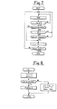
- routine DIGIT of acquisition and selection of the digits of the telephone number dialled by the user, the flow diagram wherefor is shown in Figure 7.
- This consists of a keyboard read routine TAST, which is anti-bouncing and anti-repetition in conformity with known techniques in the art which will be omitted from this description.
- the routine TAST is repeated until a key is sensed. For each digit acknowledged, a check is made on its belonging to at least one in a table of free-of-charge numbers, by activating a routine 1S to send to the line dialling pulses corresponding to the digit sensed.
- Such pulses are generated by opening and closing the relay RAL for_predetermined time.periods (shorter than the opening time required to disconnect the set from the central exchange).
- This routine will not be described in detail, it being obvious to those skilled in the art. If the number is not free-of-charge, and if the flag FS is set, the routine goes back to the block TAST, because no other operations are admitted in the "Out-of-order" state. Otherwise, the routine DIGIT lastly will check if at least one ooin is present in the ohannel, prior to giving its consent for the output of the dialling pulses. After dialling each digit, return is made to the routine DIGIT until a Datum Ready is sensed.
- the program now reads the billing pulse detector 40, and if a pulse has been received, it carries out the credit checking routine CC (Figure 8), increasing the billing total T and calculating the new leftover credit R as the difference between the total available credit C (determined in a manner to be explained) and the billing total T.
- the routine CC After checking that the ooin has not been deceiptively withdrawn from the channel, the routine CC will display the actual running credit R. If no coin is present in the channel, the routine CC sets the "Out-of-order" flag, displays this state, and opens the relay RAL for approximately 1 second in order to disconnect the set from the central exchange.
- the program checks now whether the channel is full, by comparing the actual length L of the row of coins to the rated or nominal length LC of the channel, and in that case, should the value M1 of the leading coin be smaller than the leftover credit, it will collect that coin, by driving the cash magnet 68, removing M1 from the FIFO stack in RAM, decreasing both T and C by the value M1, and decreasing the actual length L of the row of coins by the value D1 of the diameter of the collected coin.Thus, in this way the microprocessor will be able to accept the next coin introduced through the slot 18, to permit calls to arbitrary amounts independent of the maximum credit materially containable in the channel.
- the program checks now whether the leftover credit R is nil, opening in that case the RAL; otherwise it checks whether the leftover credit is less than 2 billing units, activating in that case the leftover credit blinking on the display and momentarily energizing the acoustic signal generator 44 to warn the user. Otherwise, the program checks if the line recovery key RL has been pressed. In that case it will open the RAL for about 1 second (to disconnect the set from the central exchange) and revert to the routine DIGIT to receive another number for a new talk.
- the program checks whether the handset has been hung up. In the negative case, it returns to the block IT; otherwise, since the use of the set has been terminated, the microprocessor energizes, if the call made was not addressed to a free-of-charge number, the bn-hook simulator SG, reconnecting to the loop to carry out the cash routine INC.
- the cash routine is optimized to collect the lowest credit value which is greater than or equal to the billing total.
- the cash criteria are described in the European Patent Application NO 84115605.2 of December T7, 1984 by this same Applicant and reference is made to it for a better understanding of the invention, while omitting here a detailed description thereof.
- the microprocessor 30 will open the RAL for the time required to disconnect the set from the central exchange (aboat 1. second), and then let the RAL fall back to the closed position, and will finally energize the reset relay RR which shorts out the capacitor C1 of the main power supply ( Figure 3) to cause the supply voltage to quickly drop below the uncertainty threshold and to drive the microprocessor to rest, thus avoiding unforeseeable behaviors of the microprocessor.
- the invention achieves its objects, avoiding in particular the need for a local battery, thanks to the use of a low absorption auxiliary power supply for operating the display only; avoiding the need for an operating loop, thanks to the elimination of interferences between the set and the central exchange, obtained by employing the on-hook simulator which allows the connection with the central exchnge to be continued after the utilization has terminated.
- the ROM 32 containing the program could be integrated to the microprocessor instead of being external, as could be integrated other functional blocks, such as the acoustic indicator 44 or the pulse detector 40.
- the display 20, together with its drive circuit 52 could be embodied differently, e.g. as an electrochromic display. Some of the parts described could be omitted: for instance, in some situations, the auxiliary power supply could be dispensed with,f6r example, in the instance where the display is in fact of the electrochromic type.
- the acoustic generator 44 could be omitted, or one or more of the sensors 62,64,76,78 if one or more of them is not required for anti-fraud purposes, such as where the sorter 56 or some other coin handling member is provided to perform that function.
Landscapes
- Engineering & Computer Science (AREA)
- Computer Networks & Wireless Communication (AREA)
- Computer Security & Cryptography (AREA)
- Signal Processing (AREA)
- Prepayment Telephone Systems (AREA)
Applications Claiming Priority (2)
| Application Number | Priority Date | Filing Date | Title |
|---|---|---|---|
| IT67754/84A IT1179742B (it) | 1984-07-27 | 1984-07-27 | Apparecchio telefonico per uso pubblico con microprocessore di gestione integrale |
| IT6775484 | 1984-07-27 |
Publications (2)
| Publication Number | Publication Date |
|---|---|
| EP0169507A2 true EP0169507A2 (de) | 1986-01-29 |
| EP0169507A3 EP0169507A3 (de) | 1988-06-01 |
Family
ID=11305027
Family Applications (1)
| Application Number | Title | Priority Date | Filing Date |
|---|---|---|---|
| EP85109018A Withdrawn EP0169507A3 (de) | 1984-07-27 | 1985-07-19 | Öffentlicher Fernsprecher und Mikroprozessor zur integralen Handhabung |
Country Status (3)
| Country | Link |
|---|---|
| EP (1) | EP0169507A3 (de) |
| ES (1) | ES8608761A1 (de) |
| IT (1) | IT1179742B (de) |
Cited By (5)
| Publication number | Priority date | Publication date | Assignee | Title |
|---|---|---|---|---|
| US4759054A (en) * | 1986-12-22 | 1988-07-19 | Protel, Inc. | Toll telephone system and method for maintaining or initiating loop current after resuming on-hook condition |
| US4860346A (en) * | 1986-12-22 | 1989-08-22 | Protel, Inc. | Telephone system and method operated from central office loop current |
| EP0343966A3 (de) * | 1988-05-26 | 1991-04-10 | Mars Incorporated | Steuergerät mit niedriger Leistung für einen Münzfernsprecher |
| WO1998047278A1 (en) * | 1997-04-17 | 1998-10-22 | Quadrum Telecommunications Inc. | Pay telephone with large capacity coin path |
| US6301344B1 (en) | 1997-11-05 | 2001-10-09 | Protel, Inc. | Intelligent public telephone system and method |
Family Cites Families (5)
| Publication number | Priority date | Publication date | Assignee | Title |
|---|---|---|---|---|
| NL6812919A (de) * | 1967-09-27 | 1969-03-31 | ||
| JPS5571351A (en) * | 1978-11-25 | 1980-05-29 | Tamura Electric Works Ltd | Faulty position display-type public telephone set |
| DE2938590A1 (de) * | 1979-09-24 | 1981-04-09 | Siemens AG, 1000 Berlin und 8000 München | Schaltungsanordnung fuer einen teilnehmer-muenzfernsprechapparat |
| DE3037689C2 (de) * | 1980-10-06 | 1982-09-09 | Telefonbau Und Normalzeit Gmbh, 6000 Frankfurt | Schaltungsanordnung zur Überwachung der Funktionsfähigkeit von Münzfernsprechern |
| CH654705A5 (de) * | 1982-04-27 | 1986-02-28 | Autelca Ag | Schaltungsanordnung fuer einen muenzfernsprecher. |
-
1984
- 1984-07-27 IT IT67754/84A patent/IT1179742B/it active
-
1985
- 1985-06-26 ES ES544591A patent/ES8608761A1/es not_active Expired
- 1985-07-19 EP EP85109018A patent/EP0169507A3/de not_active Withdrawn
Cited By (6)
| Publication number | Priority date | Publication date | Assignee | Title |
|---|---|---|---|---|
| US4759054A (en) * | 1986-12-22 | 1988-07-19 | Protel, Inc. | Toll telephone system and method for maintaining or initiating loop current after resuming on-hook condition |
| US4860346A (en) * | 1986-12-22 | 1989-08-22 | Protel, Inc. | Telephone system and method operated from central office loop current |
| EP0343966A3 (de) * | 1988-05-26 | 1991-04-10 | Mars Incorporated | Steuergerät mit niedriger Leistung für einen Münzfernsprecher |
| WO1998047278A1 (en) * | 1997-04-17 | 1998-10-22 | Quadrum Telecommunications Inc. | Pay telephone with large capacity coin path |
| US6301344B1 (en) | 1997-11-05 | 2001-10-09 | Protel, Inc. | Intelligent public telephone system and method |
| US6850607B2 (en) | 1997-11-05 | 2005-02-01 | Protel, Inc. | Intelligent vending system and method |
Also Published As
| Publication number | Publication date |
|---|---|
| ES8608761A1 (es) | 1986-07-16 |
| IT1179742B (it) | 1987-09-16 |
| IT8467754A0 (it) | 1984-07-27 |
| ES544591A0 (es) | 1986-07-16 |
| IT8467754A1 (it) | 1986-01-27 |
| EP0169507A3 (de) | 1988-06-01 |
Similar Documents
| Publication | Publication Date | Title |
|---|---|---|
| EP0296179B1 (de) | Überwachungs- und rapportierungssystem mit fernverbindung | |
| US5424940A (en) | Computer controlled system providing functions within a laundromat facility | |
| EP0433343A1 (de) | Verbesserungen an einem beweglichen bezahlfernsprechersystem | |
| US4999763A (en) | Self service access controller | |
| US4192972A (en) | Pay-telephone station with deferred collection | |
| US5896446A (en) | Coin operated telephone auditor | |
| JP2911933B2 (ja) | コイン作動電話器用低電力制御装置 | |
| EP0169507A2 (de) | Öffentlicher Fernsprecher und Mikroprozessor zur integralen Handhabung | |
| KR0156175B1 (ko) | 전화기의 통화요금 디스플레이장치 및 방법 | |
| EP0166745B1 (de) | Betrugschutz für eine elektronische münzfernsprechanlage | |
| GB1565445A (en) | Prepayment telephone apparatus | |
| US4599492A (en) | Coin-telephone auditor | |
| US5809124A (en) | Coin charging system for mobile telephony | |
| JP3133456B2 (ja) | 自動販売機の硬貨処理装置 | |
| AU674676B2 (en) | Coin cashing system for mobile telefony | |
| EP0134693A2 (de) | Münzfernsprecher | |
| JPS6217277B2 (de) | ||
| KR900007712B1 (ko) | 공중전화기의 관리장치 | |
| JPH0332947B2 (de) | ||
| JPH0137903B2 (de) | ||
| JPS63254850A (ja) | カ−ド式電話機 | |
| JPS58173955A (ja) | 公衆電話機 | |
| JPH0137901B2 (de) | ||
| JP2003047515A (ja) | 財布装置及び貯金箱装置 | |
| JPH0325114B2 (de) |
Legal Events
| Date | Code | Title | Description |
|---|---|---|---|
| PUAI | Public reference made under article 153(3) epc to a published international application that has entered the european phase |
Free format text: ORIGINAL CODE: 0009012 |
|
| AK | Designated contracting states |
Designated state(s): BE CH DE FR GB LI |
|
| PUAL | Search report despatched |
Free format text: ORIGINAL CODE: 0009013 |
|
| AK | Designated contracting states |
Kind code of ref document: A3 Designated state(s): BE CH DE FR GB LI |
|
| 17P | Request for examination filed |
Effective date: 19881121 |
|
| 17Q | First examination report despatched |
Effective date: 19901217 |
|
| STAA | Information on the status of an ep patent application or granted ep patent |
Free format text: STATUS: THE APPLICATION IS DEEMED TO BE WITHDRAWN |
|
| 18D | Application deemed to be withdrawn |
Effective date: 19910430 |
|
| RIN1 | Information on inventor provided before grant (corrected) |
Inventor name: MONDARDINI, MASSIMO |