EP0169701A1 - Entfernungsmesser - Google Patents
Entfernungsmesser Download PDFInfo
- Publication number
- EP0169701A1 EP0169701A1 EP85305057A EP85305057A EP0169701A1 EP 0169701 A1 EP0169701 A1 EP 0169701A1 EP 85305057 A EP85305057 A EP 85305057A EP 85305057 A EP85305057 A EP 85305057A EP 0169701 A1 EP0169701 A1 EP 0169701A1
- Authority
- EP
- European Patent Office
- Prior art keywords
- echo
- chosen
- return
- time
- echoes
- Prior art date
- Legal status (The legal status is an assumption and is not a legal conclusion. Google has not performed a legal analysis and makes no representation as to the accuracy of the status listed.)
- Granted
Links
- 238000002592 echocardiography Methods 0.000 claims description 42
- 230000005540 biological transmission Effects 0.000 claims description 26
- 238000005259 measurement Methods 0.000 claims description 24
- 239000013078 crystal Substances 0.000 description 10
- 230000003321 amplification Effects 0.000 description 8
- 238000003199 nucleic acid amplification method Methods 0.000 description 8
- 101100443251 Saccharomyces cerevisiae (strain ATCC 204508 / S288c) DIG2 gene Proteins 0.000 description 6
- 101100041128 Schizosaccharomyces pombe (strain 972 / ATCC 24843) rst2 gene Proteins 0.000 description 6
- 230000000694 effects Effects 0.000 description 5
- 101100041125 Arabidopsis thaliana RST1 gene Proteins 0.000 description 3
- 101100443250 Saccharomyces cerevisiae (strain ATCC 204508 / S288c) DIG1 gene Proteins 0.000 description 3
- 230000006870 function Effects 0.000 description 3
- 238000002604 ultrasonography Methods 0.000 description 3
- 238000010586 diagram Methods 0.000 description 2
- 238000000034 method Methods 0.000 description 2
- 230000000630 rising effect Effects 0.000 description 2
- 240000007320 Pinus strobus Species 0.000 description 1
- 239000003990 capacitor Substances 0.000 description 1
- 230000001934 delay Effects 0.000 description 1
- 238000005538 encapsulation Methods 0.000 description 1
- 230000005764 inhibitory process Effects 0.000 description 1
- 238000007689 inspection Methods 0.000 description 1
- 238000012986 modification Methods 0.000 description 1
- 230000004048 modification Effects 0.000 description 1
- 230000003313 weakening effect Effects 0.000 description 1
Images


Classifications
-
- G—PHYSICS
- G01—MEASURING; TESTING
- G01S—RADIO DIRECTION-FINDING; RADIO NAVIGATION; DETERMINING DISTANCE OR VELOCITY BY USE OF RADIO WAVES; LOCATING OR PRESENCE-DETECTING BY USE OF THE REFLECTION OR RERADIATION OF RADIO WAVES; ANALOGOUS ARRANGEMENTS USING OTHER WAVES
- G01S15/00—Systems using the reflection or reradiation of acoustic waves, e.g. sonar systems
- G01S15/02—Systems using the reflection or reradiation of acoustic waves, e.g. sonar systems using reflection of acoustic waves
- G01S15/06—Systems determining the position data of a target
- G01S15/08—Systems for measuring distance only
- G01S15/10—Systems for measuring distance only using transmission of interrupted, pulse-modulated waves
- G01S15/101—Particularities of the measurement of distance
Definitions
- This invention relates to the sensing of distances in air, by means of ultrasound (or possibly audible sound) which is transmitted as a pulse from a distance sensing device and reflected back to it by an object such as a wall, serving as a target at a distance from the device.
- the time from transmission of the pulse to receipt of its echo is measured, and provides an indication of the distance.
- Equipment for this purpose is already known, for example, the Sonarange device made by Freedom Engineering Limited, the apparatus described in U.K. patent specification No. 2 082 325A of Sonic Tape PLC, and that described in German OLS 2 755 556A of Dieter Haffer.
- the device will be used to measure distances.
- One particular application of such devices is for building surveyors and estate agents, measuring the rooms within a building.
- At least some known apparatus is constructed so that it largely does not respond to echoes from off the centre line of the transmitted pulse. Nevertheless circumstances arise where a user cannot be sure which of possible target surfaces is giving the echo to which the apparatus responds. For example it may be difficult to be sure that the apparatus is measuring the distance to a wall, rather than to a table standing in front of the wall.
- W e have realised that it would be desirable to provide a facility enabling the apparatus to respond to one, or possibly any of several, echoes received after the first echo to which it is capable of responding, and enabling the user to select among the plurality of echoes.
- Such a facility could for example enable a user to ignore an unwanted echo, and make use of a desired echo returning from further away.
- the facility could for example be employed to measure the distance to an object (say a wall) followed by measurement of a greater distance, such asthrough a doorway in the wall to another wall beybnd.
- While the invention is principally conceived for use where distances are measured, it could conceivably be applied in circumstances where there is no measurement read out.
- One example would be devices which sense whether the distance to a reflecting object is between a pair of prescribed limits, or is above or below a prescribed limit value.
- Another example would be devices which are directly coupled to give automatic actuation of something else, such as a camera rangefinder automatically coupled to the focus adjustment.
- apparatus for sensing distances in air comprising means to transmit at least one ultrasonic or sonic signal, means to detect receipt of an echo and means to measure or otherwise sense the time elapsed from transmission to return of the echo characterised in that the apparatus possesses ability to detect a subsequent echo and measure or otherwise sense the time from transmission to return thereof, as well as possessing ability to detect a first echo and measure or otherwise sense the time from transmission to return of the first echo.
- the apparatus detects the first echo and at least one subsequent echo, measures or senses the respective times from transmission to return of each one of the detected echoes, and then offers a plurality of measured or sensed values for inspection by a user. For instance, a plurality of measured times could be converted to respective measurements of distance and then the apparatus might display to a user the distance of the target returning the first echo, the distance of the target returning any second echo and perhaps the distances of any targets returning subsequent echoes, up to a maximum range. These might be displayed simultaneously on an appropriate display or they might be displayed in succession on a display suitable for displaying only one such distance at a time. In either case the user could then pick out whichever value(s) appeared to be the distance(s) he was attempting to measure.
- apparatus includes selectively operable control means to choose between successive echoes returning from different distances, or to choose between respective values associated with such successive echoes.
- apparatus for sensing distances in air comprising means to transmit at least one ultrasonic or sonic signal, means to detect receipt of at least one echo and time sensing means to measure or otherwise sense the time elapsed from transmission to return of the echo, characterised by selectively operable control means to choose between echoes from different distances and cause the apparatus to measure or otherwise sense the time elapsed from transmission to return of the chosen echo, or to choose between measured or sensed values respectively associated with echoes from different distances.
- the transmitted signal preferably consists of one, or possibly a succession of pulses of sound or ultrasound, each pulse containing a number of cycles of the transmitted frequency or frequencies.
- a pulse might also be termed a "burst".
- the apparatus should be able to detect more than one echo from the same transmitted pulse.
- a transmitted pulse or a succession of transmitted pulses might be employed for detecting one echo, and thereafter a further transmitted pulse or succession of pulses employed to detect a different echo from further away while the detecting means is inhibited from detecting echoes until time-for return of the first echo has passed.
- This further transmission should of course take place while the apparatus and the target(s) remain in the same positions.
- the means to sense the elapsed time produces a numerical measured value, and means are provided to display a digital distance measurement derived from the measured value. If the apparatus includes the selectively operable control means mentioned above, these can cause the apparatus to display a distance measurement derived from the time from transmission to return of the chosen echo.
- the means to sense the elapsed time functions to sense only whether the time is above or below a certain limit value, or is between a pair of limit values, without creating a numerical measurement of the time.
- apparatus embodying this invention may only be able to respond to first and second echoes. However, it is preferably able to respond to a greater plurality of echoes.
- Selectively operable control means may have multiple settings, for selecting between echoes from more than two different distances.
- control means may have a single action and be operable repeatedly to increment through echoes from different distances. For example it might be operated once to choose the second echo, operated again to choose the third echo and so on.
- control means may take the form of a push button .
- the apparatus will generally only respond to echoes of at least a qualifying amplitude. That amplitude or the amount of prior amplification of electrical signals derived from returning echoes may vary to compensate for the weakening of an echo with distance travelled.
- the apparatus When the apparatus includes selectively operable control means, the apparatus is preferably arranged to default by treating the first echo which is above a qualifying amplitude and from beyond a minimum range as the chosen one, unless the selectively operable control means has been operated.
- the apparatus may detect all echoes of a single transmitted signal, provided these have at least a qualifying amplitude, and return from sufficiently different distances between maximum and minimum limits. Selectively operable control means can then act to choose between the electrical signals derived from each of these echoes.
- the apparatus may include means to count a variable number (n) of echoes which are above a qualifying amplitude, while continuing time measurement. Conveniently the last of these echoes will bring about an enabling of the time sensing means to respond to the subsequent said signal, which will be that associated with the chosen echo.
- the selectively operable control means may take the form of a push button, each press on which acts to increment the variable number (n) of echo signals which are counted and passed over before the chosen echo is received.
- the apparatus might be arranged to store the time from transmission to return of the last "unwanted” echo, and then for a subsequent transmission ignore any and all echoes until the stored time had elapsed.
- the next following echo having more than a qualifying amplitude would be detected as the chosen echo.
- the selectively operable means could take the form of a push button. Pressing it would step on to the next echo, by treating the most recently measured time to a chosen echo for an average from several repeated measurements) as the time during which all echoes are ignored. Of course it would need to be ensured that the later part of the last "unwanted” echo was ignored, as well as its beginning.
- the apparatus may be arranged to transmit repeated pulses automatically, to detect receipt of an echo corresponding to each pulse transmitted, and to maintain a display of a distance measurement which might be derived from an echo of the most recent pulse transmitted, or might be an average of values from echoes of several pulses. In either event, it is suitable for the selectively operable control means to cause the apparatus to pass over a selected number of echoes from each transmitted pulse before the chosen echo is received, as mentioned above.
- a particularly preferred form of the apparatus includes a number of the above features. It has selectively operable control means to choose between successive echoes from different distances, and cause the apparatus to measure or otherwise sense the time elapsed from transmission to return of the chosen echo: if the control means is not operated, the first echo of qualifying amplitude is chosen; if the means is operated once both the first echo and any second echo of qualifying amplitude are detected, but the apparatus measures or otherwise senses the time elapsed from transmission to return of the second echo; if the means is operated again the first, and second and any third echoes of qualifying amplitude are detected but the apparatus measures or otherwise senses the time elapsed from transmission to return of the third echo; and so on.
- Fig. 1 the output of a crystal oscillator running at somewhat over 100 KHz is fed to a decades counter 12, and to a dividing and logic circuit 14. This divides the oscillator signal and at intervals of about 200 m sec. produces three short output pulses in succession, hereinafter designated RST1, RST2 and TREN. They appear in that order on respective outputs, at intervals of, say, 1 m sec.
- the TREN pulse triggers a monostable 17 to produce a pulse which enables a 40 KHz oscillator 18 for approximately 0.6 m sec, so that it generates a 40 KHz pulse of that length, approximately twenty four cycles.
- the 40 KHz pulse is amplified at 20 and supplied to an output transducer 22 which transmits it as an ultrasonic pulse.
- transducer 30 Any echo is received by transducer 30.
- the echo signal passes through a circut 32 functioning as an analog switch.
- This circuit is inhibited by TREN, and it contains an RC network which extends the period of inhibition so that no echo can pass during a period from the start of transmission to slightly after the end of transmission. This eliminates spurious echoes by suppressing all echoes from within a minimum range of approximately 45 cm.
- the echo signal (s) pass onto a variable amplifying circuit 34.
- a ramp generator 36 is initiated by the TREN pulse to produce a progressively rising output. This controls the amount of amplication given by the circuit 34, so that this also rises progressively with time elapsed since the ultrasonic pulse was transmitted. This rising amplification approximately compensates for the attenuation of the ultrasonic pulse with travel through air. By virtue of this, all true echoes returning from along the centre axis of the transmitted beam are amplified to an approximately similar signal amplitude, and can be distinguished from weaker, spurious echoes, e.g. reflected by objects which lie off the central axis of the transmitted beam. This expedient is known per se and described in U.K. 2082325A mentioned above.
- variable amplification stage 34 could be less than unity, and it would also be feasible to,employ a variable attenuator here with attenuation reducing progressively with time following transmission of an ultrasonic pulse.
- the echo signals are fed to further stages of amplification 38, a tuned circuit 40 to filter out any spurious received signals of the wrong frequency, and then a detector stage 42.
- This delivers an output signal if an echo signal which has passed through the preceding stages is above a predetermined minimum amplitude, and accordingly is recognised as a genuine echo from a target object along the centre axis of the transmitted pulse.
- the leading edge of the TREN pulse starts the counter 12 for the crystal oscillator clock signals.
- Each transmitted pulse may give rise to several echoes from different target surfaces approximately along the centre axis of the transmitted beam. These echoes will lead to echo signals of sufficient amplitude to pass the detector stage 42.
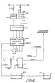
- one of these echo signals is chosen and converted to a signal (designated STOP) which stops the counter 12. This function is performed by the logic circuitry shown in F ig. 2 .
- the echo signals from the detector stage 42 are fed to trigger a monostable 44.
- the monostable 44 gives one and only one voltage pulse which is fed to the clock input of a D-type flip-flop 46 and to the clock input of a presettable down counter 48.
- the four outputs of the counter 48 are connected to a 4-input NOR gate 49 whose output is the input to the flip-flop 46. In the default state, the output of counter 48 is zero so the input to the flip-flop 46 is high.
- the leading edge of the first echo pulse from the monostable 44 clocks the flip-flop 46 to give a logic high signal on the Q output of the flip-flop 46.
- This 'output (designated STOP) is connected to stop the counter 12. Thus its count when stopped represents the time from transmission of the ultrasonic pulse to receipt of the first echo above the qualifying minimum amplitude set by the detector stage 42.
- the device has a push button 50 (the "NEXT” button) connected through a debouncing circuit 51 to the clock input of an up counter 52.
- the device also has a push button 54 for clearing the effect of the next button. This is connected, via a Schmitt trigger 56, to the reset input of the counter 52.
- the outputs of the up counter 52 are connected to parallel load inputs of the presettable counter 48.
- the "load” input of the counter 48 is connected to RST2 from the divide and logic circuit 14. So, every RST2 pulse presets the counter 48 to the output of up counter 52.
- each RST2 pulse will set counter 48 to one.
- the input to flip-flop 46 will then be low so that when the leading edge of the first echo pulse clocks the flip-flop 46, its Q output stays low and the counter 12 continues to count. However, the leading edge of the first echo pulse will decrement the counter 48 to zero. Then the second echo pulse from the same transmitted pulse will give a high Q output, as STOP to the counter 12.
- each push will increment the counter 48 to a higher output (n) provided the counter does not go past its maximum count. Then the first (n) echo pulses from each transmitted pulse will progressively decrement the counter 52 to zero, whereafter the following echo pulse (the n + 1 th) will give a STOP output from flip-flop 46 to stop the counter 12.
- the effects of pressing the NEXT button 50 once, or more times, are annulled by pressing the button 54 which resets the counter 48 to zero.
- the counter 48 is also set to zero when the device is turned on, by virtue of the resistor and capacitor network 57 connected to the Schmitt trigger 56 to take the reset input of up counter 52 high initially. (The button 54 could be dispensed with and the effect of the NEXT button 50 cleared simply by turning off the device at the end of a measurement).
- the count recorded in it is directly proportional to the distance from the device to the target object which returned the chosen echo.
- the next RST1 pulse strobes this count into a buffer and display driver 60 which displays it on a seven segment display 62.
- the next RST2 pulse resets the counter 12.
- the display 62 shows the latest distance measurement made.
- the frequency of the oscillator 10 may be chosen so that the count from counter 12 which is displayed on the display 62 is a direct measurement in metres, or alternatively in feet, from the device to the target which returned the chosen echo.
- the frequency of oscillator 10 may be adjusted automatically to compensate for variations in temperature and hence variations of the speed of sound in air.
- a microprocessor 70 has parallel input and output ports, and is provided with read-only and random access memory 71, 73. It is connected to a key pad 72, and to drivers 74 for a seven-segment display 76. This is all conventional, and the microrpocessor repeatedly scans the key board 72, as is also conventional.
- One key on the board 72 is dedicated as a "NEXT" button.
- the operating program of the microprocessor 70 causes it to generate a short pulse (TREN) on one line 77 of an output port.
- TREN pulse enables a 40 KHz oscillator 18 whose output signal is amplified at 20 and supplied to an output transducer 22.
- the 40 KHz signal is also fed to a counter 26 which counts the transmitted cycles until twenty four cycles have been generated, whereupon the counter 26 inhibits the 40 KHz oscillator, terminating the transmitted ultrasonic pulse and holding the oscillator 18 inhibited until the next TREN pulse.
- the counter 26 should of course be reset between TREN pulses.
- the transducer 22 is also used for reception of echoes.
- the received echo signals are supplied to an analog switch circuit 32 just as in Fig. 1.
- the input to this analog switch circuit is connected across a pair of diodes in parallel opposition, which are in series with the transducer 22.
- a counter 26 to fix the length of a transmitted pulse and/or the feature of a single transducer 22 could be employed in the embodiment of Fig. 1.
- a monostable 17 could be used to fix the transmitted pulse length in this embodiment and/or a separate receiving transducer 30 could be employed here as in Fig. 1.
- the received echo signals are amplified and detected as in the embodiment of Fig. 1. Again any echo signals passed by the detector stage 42 trigger a monostable 44 so as again to give a single voltage pulse (designated INT) for each echo.
- INT single voltage pulse
- the INT pulses from the monostable 44 are used in two ways. Each one is fed to an interrupt request input 79 of the microprocessor. Secondly they are fed to one input of a NAND gate 80. The output from this passes along line 81 to one input of a flip-flop consisting of a pair of NAND Schmitt triggers 82. The other input to this flip-flop receives an inversion of the TREN pulses (TR ⁇ ).
- One output of the Schmitt trigger 82 is connected via line 83 to a NAND gate 84.
- a crystal oscillator 86 supplies clock pulses via the gate 84 and line 85 to a binary counter 88. The output of this is connected to a parallel input port of the microprocessor 7 0 .
- the microprocessor In use the microprocessor generates an active low signal (designated CONT) on one line of a parallel output port. This is connected to the other input of the gate 80.
- CONT active low signal
- TR E N causes transmission of an ultrasonic pulse as described in connection with Fig. 1 . When it does this there will necessarily be no INT signal and so the line 81 is necessarily high. As TREN goes high, TREN goes low driving line 83 high, and hence allowing the crystal oscillator pulses to pass through the gate 84 to the counter 88. In this way TREN starts the count. When the TREN pulse finishes, TREK reverts to a high state but this does not change the state of the flip-flop formed by the Schmitt triggers 82.
- the microprocessor keeps CONT high and when the first echo signal is passed by the detector stage 42 the INT pulse from the monostable 44 interruptsthe microprocessor and also sends line 81 and hence line 83 low. Consequently the crystal oscillator pulses can no longer pass through the gate 84 to the counter. In this way the pulse from the monostable 44 stops the count virtually immediately. Moreover, the short delay arising from the propagation delays of the gates 80, 82 and 84 is always the same.
- the microprocessor 70 reads the (stopped) count in the course of servicing the interrupt from monostable 44. However, it will be appreciated that the interrupt servicing routine is not itself being relied upon to stop the count.
- CONT may go low before, during or after the TREN pulse: this does not matter provided CONT is low before the earliest possible receipt of an echo.
- the operating program of the microprocessor can allow the NEXT button to be pressed a plurality of times (n times) to pass over the first n echo signals which pass the detector stage 42.
- the microprocessor then counts the interrupts received from the monostable 44 and in servicing the n'th interrupt it sends CONT high.
- the first n echoes do not stop the count of crystal oscillator pulses but the following (i.e. the n + 1'th) echo does stop the count.
- the microprocessor When the microprocessor services the interrupt from the chosen echo it reads the (stopped) count from the counter 12 and from it calculates the distance from the measuring device to the target object which reflected the chosen echo. The distance may be displayed on the seven segment display, or may be used by the microprocessor for further calculation.
- the device preferably includes means enabling the microprocessor to read in a digital measurement of temperature, so that it can allow for the ambient temperature in calculating the distance to the target object.
- the microprocessor must reset the counter 88 before the next TREN pulse. This is done by a pulse on line 93 which is another line of an output port.
- the counter in the absence of the chosen echo, the counter will reach its maximum count, and overflow, before the next TREN pulse.
- the resulting carry signal from the counter on line 91 is used as an interrupt of higher priority.
- the microprocessor In servicing either this interrupt or an interrupt by the chosen echo, the microprocessor resets the counter.
- the TREN pulses may be generated at regularly spaced intervals, or may follow the chosen echo, or counter overflow, whichever happens first.
- the microprocessor takes CONT low during the appropriate number of interrupts after every TREN pulse, until either the effect of the NEXT button is cleared, or until the NEXT button is pressed again to increase the number of echoes which are passed over before the chosen echo.
- the effect of the NEXT button can be cancelled by switching the device off and on again, or by means of a CLEAR button on the keypad 72.
- the crystal oscillator 86 preferably runs at lMHz. However, a lower frequency might be employed, for example if it proved impractical to count such a high frequency.
- the pulses from crystal oscillator 86 could provide the clock signal for the microprocessor.
- the counter 88, and/or the display drivers 74 could possibly be incorporated on the same chip (or at any rate within the same integrated circuit encapsulation) as the microprocessor and its memory. If a microprocessor was employed which did not have parallel input and output ports, a separate parallel input/output chip would be used to provide these, as is conventional.
- variable amplification is achieved with a ramp generator 36 governing a variable amplifier 34.
- An alternative, improved technique for variable amplification is disclosed in our UK Patent Application 84.18216, from which a second UK application 85. now claims priority. A copy of that second UK application is being placed on file with the present application.
- a user would normally put the device in position to take a measurement. He would operate it for long enough to transmit several ultrasonic pulses, and thereby make sure that the distance measurement appearing on the display was steady. Then if the user wished to measure the distance to a more remote target he would press the NEXT button once, and again operate the device for long enough to be sure that a steady figure was appearing on the display. This same procedure of measuring with several transmitted pulses might be repeated several times in appropriate circumstances, pressing the NEXT button once between each measurement so as to go on to the next echo. Finally the device would be switched off, and carried away.
- the counter 12 or 88 could be preset each time an ultrasonic pulse was transmitted.
- the preset count would correspond to a predetermined distance.
- the clock signals from the crystal oscillator 10 or 86 would then decrement the counter, and the device would be arranged to indicate whether the chosen echo was or was not received before the counter had decremented to zero. In such an arrangement the exact time for return of the chosen echo is not recorded, but it is sensed as being above or below a prescribed value.
- Another possibility within this invention would be for the apparatus to retain and display the highest distance previously measured if, on pressing the NEXT button, no further echo were detected from within a maximum range. In this event a letter F could also. appear on the display to indicate that it was the measurement for the final echo. With this arrangement a user would take a measurement and press the NEXT button repeatedly until the "F" appeared (and the displayed measurement remained constant). He would then know that this was the measurement from "the farthest target.
Landscapes
- Physics & Mathematics (AREA)
- Engineering & Computer Science (AREA)
- Radar, Positioning & Navigation (AREA)
- Remote Sensing (AREA)
- Acoustics & Sound (AREA)
- Computer Networks & Wireless Communication (AREA)
- General Physics & Mathematics (AREA)
- Measurement Of Velocity Or Position Using Acoustic Or Ultrasonic Waves (AREA)
Applications Claiming Priority (2)
| Application Number | Priority Date | Filing Date | Title |
|---|---|---|---|
| GB848418213A GB8418213D0 (en) | 1984-07-17 | 1984-07-17 | Distance sensing |
| GB8418213 | 1984-07-17 |
Publications (2)
| Publication Number | Publication Date |
|---|---|
| EP0169701A1 true EP0169701A1 (de) | 1986-01-29 |
| EP0169701B1 EP0169701B1 (de) | 1990-12-12 |
Family
ID=10564016
Family Applications (1)
| Application Number | Title | Priority Date | Filing Date |
|---|---|---|---|
| EP85305057A Expired EP0169701B1 (de) | 1984-07-17 | 1985-07-16 | Entfernungsmesser |
Country Status (4)
| Country | Link |
|---|---|
| US (1) | US4731762A (de) |
| EP (1) | EP0169701B1 (de) |
| DE (1) | DE3580874D1 (de) |
| GB (1) | GB8418213D0 (de) |
Cited By (2)
| Publication number | Priority date | Publication date | Assignee | Title |
|---|---|---|---|---|
| AU626921B2 (en) * | 1984-03-22 | 1992-08-13 | Salubre Investments Limited | The processing of reflected signals |
| GB2266369A (en) * | 1992-04-16 | 1993-10-27 | Meditronics Limited | Vehicle manoeuvring aid |
Families Citing this family (37)
| Publication number | Priority date | Publication date | Assignee | Title |
|---|---|---|---|---|
| US4953141A (en) * | 1987-08-28 | 1990-08-28 | Recurrent Solutions Limited Partnership | Sonic distance-measuring device |
| US5235511A (en) * | 1988-06-09 | 1993-08-10 | Spectra-Physics, Inc. | Method for automatic depth control for earth moving and grading |
| US4918608B1 (en) * | 1988-06-09 | 1996-07-02 | Christopher O Middleton | Method for automatic depth control for earth moving and grading |
| US4914593B1 (en) * | 1988-06-09 | 1995-01-17 | Spectra Physics | Method for automatic depth control for earth moving and grading |
| US4975889A (en) * | 1988-06-16 | 1990-12-04 | Petrucelli Steven P | Acoustic ranging apparatus and method |
| US5062088A (en) * | 1990-10-09 | 1991-10-29 | Lundahl Instruments, Inc. | Acoustic measuring system |
| US5199299A (en) * | 1991-03-11 | 1993-04-06 | Iowa State University Research Foundation, Inc. | Ultrasonic unipolar pulse/echo instrument |
| US5453932A (en) * | 1994-01-12 | 1995-09-26 | Advanced Grade Technology, Inc. | Device and method for detecting and elimination of spurious ultrasonic ranging echoes |
| DE19514307A1 (de) * | 1994-05-19 | 1995-11-23 | Siemens Ag | Duplexer für ein Ultraschallabbildungssystem |
| US5796682A (en) * | 1995-10-30 | 1998-08-18 | Motorola, Inc. | Method for measuring time and structure therefor |
| US20020059177A1 (en) * | 2000-07-11 | 2002-05-16 | Paul Hansen | Method of forming a template and associated computer device and computer software program product |
| AU2003294296A1 (en) * | 2002-11-12 | 2004-09-06 | General Dynamics Advanced Information Systems | A method and system for in-air ultrasonic acoustical detection and characterization |
| KR20050014051A (ko) * | 2003-07-29 | 2005-02-07 | 안희태 | 초음파 신호에서 주파수 분리를 이용한 거리측정 방법 및장치 |
| US7554653B2 (en) * | 2006-12-01 | 2009-06-30 | Trimble Ab | Multitarget |
| US9259179B2 (en) | 2012-02-27 | 2016-02-16 | Orthosensor Inc. | Prosthetic knee joint measurement system including energy harvesting and method therefor |
| US8421479B2 (en) * | 2009-06-30 | 2013-04-16 | Navisense | Pulsed echo propagation device and method for measuring a parameter |
| US8714009B2 (en) | 2010-06-29 | 2014-05-06 | Orthosensor Inc. | Shielded capacitor sensor system for medical applications and method |
| US8826733B2 (en) | 2009-06-30 | 2014-09-09 | Orthosensor Inc | Sensored prosthetic component and method |
| US9839390B2 (en) | 2009-06-30 | 2017-12-12 | Orthosensor Inc. | Prosthetic component having a compliant surface |
| US8679186B2 (en) | 2010-06-29 | 2014-03-25 | Ortho Sensor Inc. | Hermetically sealed prosthetic component and method therefor |
| US8701484B2 (en) | 2010-06-29 | 2014-04-22 | Orthosensor Inc. | Small form factor medical sensor structure and method therefor |
| US9462964B2 (en) | 2011-09-23 | 2016-10-11 | Orthosensor Inc | Small form factor muscular-skeletal parameter measurement system |
| US8707782B2 (en) | 2009-06-30 | 2014-04-29 | Orthosensor Inc | Prosthetic component for monitoring synovial fluid and method |
| US8720270B2 (en) | 2010-06-29 | 2014-05-13 | Ortho Sensor Inc. | Prosthetic component for monitoring joint health |
| US9161717B2 (en) | 2011-09-23 | 2015-10-20 | Orthosensor Inc. | Orthopedic insert measuring system having a sealed cavity |
| US9414940B2 (en) | 2011-09-23 | 2016-08-16 | Orthosensor Inc. | Sensored head for a measurement tool for the muscular-skeletal system |
| US8911448B2 (en) | 2011-09-23 | 2014-12-16 | Orthosensor, Inc | Device and method for enabling an orthopedic tool for parameter measurement |
| US9839374B2 (en) | 2011-09-23 | 2017-12-12 | Orthosensor Inc. | System and method for vertebral load and location sensing |
| US9271675B2 (en) | 2012-02-27 | 2016-03-01 | Orthosensor Inc. | Muscular-skeletal joint stability detection and method therefor |
| US9844335B2 (en) | 2012-02-27 | 2017-12-19 | Orthosensor Inc | Measurement device for the muscular-skeletal system having load distribution plates |
| US9622701B2 (en) | 2012-02-27 | 2017-04-18 | Orthosensor Inc | Muscular-skeletal joint stability detection and method therefor |
| US20140135744A1 (en) | 2012-11-09 | 2014-05-15 | Orthosensor Inc | Motion and orientation sensing module or device for positioning of implants |
| US9408557B2 (en) | 2013-03-18 | 2016-08-09 | Orthosensor Inc. | System and method to change a contact point of the muscular-skeletal system |
| US11793424B2 (en) | 2013-03-18 | 2023-10-24 | Orthosensor, Inc. | Kinetic assessment and alignment of the muscular-skeletal system and method therefor |
| US11534316B2 (en) | 2017-09-14 | 2022-12-27 | Orthosensor Inc. | Insert sensing system with medial-lateral shims and method therefor |
| US11812978B2 (en) | 2019-10-15 | 2023-11-14 | Orthosensor Inc. | Knee balancing system using patient specific instruments |
| CN113917397A (zh) * | 2021-09-17 | 2022-01-11 | 深圳市睿联技术股份有限公司 | 测距方法、装置、系统及计算机可读存储介质 |
Citations (4)
| Publication number | Priority date | Publication date | Assignee | Title |
|---|---|---|---|---|
| US3545861A (en) * | 1966-04-08 | 1970-12-08 | Hughes Aircraft Co | Selective target ranging system |
| US3743419A (en) * | 1969-07-09 | 1973-07-03 | Bofors Ab | Ranging system |
| DE2755556A1 (de) * | 1977-12-13 | 1979-06-21 | Dieter Dipl Ing Dr Ing Haffer | Digitales abstands-messgeraet |
| WO1981002472A1 (en) * | 1980-02-22 | 1981-09-03 | Sonic Tape Ltd | A sonar distance sensing apparatus |
Family Cites Families (9)
| Publication number | Priority date | Publication date | Assignee | Title |
|---|---|---|---|---|
| FR1514156A (fr) * | 1966-11-08 | 1968-02-23 | Realisations Ultrasoniques Sa | Appareil de mesure de niveaux par réflexion d'impulsions ultrasonores |
| NO125292B (de) * | 1968-07-12 | 1972-08-14 | Bofors Ab | |
| US3942149A (en) * | 1974-08-19 | 1976-03-02 | Texas Instruments Incorporated | Solid state depth sounder |
| US4122428A (en) * | 1976-11-22 | 1978-10-24 | Morrow Jr Ray E | Marine detection apparatus |
| US4386409A (en) * | 1980-09-23 | 1983-05-31 | Petroff Alan M | Sewage flow monitoring system |
| US4439846A (en) * | 1981-11-18 | 1984-03-27 | Polaroid Corporation | Sonar rangefinder system |
| US4459689A (en) * | 1981-12-28 | 1984-07-10 | Polaroid Corporation | Multiple zone object detection system |
| US4578997A (en) * | 1982-01-04 | 1986-04-01 | Fischer & Porter | Time-shaped AGC for ultrasonic liquid level meter of the echo-ranging type |
| US4574368A (en) * | 1983-02-23 | 1986-03-04 | Record Industrial Company | Distance measuring system using ultrasonic ranging |
-
1984
- 1984-07-17 GB GB848418213A patent/GB8418213D0/en active Pending
-
1985
- 1985-07-12 US US06/754,641 patent/US4731762A/en not_active Expired - Fee Related
- 1985-07-16 EP EP85305057A patent/EP0169701B1/de not_active Expired
- 1985-07-16 DE DE8585305057T patent/DE3580874D1/de not_active Expired - Fee Related
Patent Citations (4)
| Publication number | Priority date | Publication date | Assignee | Title |
|---|---|---|---|---|
| US3545861A (en) * | 1966-04-08 | 1970-12-08 | Hughes Aircraft Co | Selective target ranging system |
| US3743419A (en) * | 1969-07-09 | 1973-07-03 | Bofors Ab | Ranging system |
| DE2755556A1 (de) * | 1977-12-13 | 1979-06-21 | Dieter Dipl Ing Dr Ing Haffer | Digitales abstands-messgeraet |
| WO1981002472A1 (en) * | 1980-02-22 | 1981-09-03 | Sonic Tape Ltd | A sonar distance sensing apparatus |
Cited By (3)
| Publication number | Priority date | Publication date | Assignee | Title |
|---|---|---|---|---|
| AU626921B2 (en) * | 1984-03-22 | 1992-08-13 | Salubre Investments Limited | The processing of reflected signals |
| GB2266369A (en) * | 1992-04-16 | 1993-10-27 | Meditronics Limited | Vehicle manoeuvring aid |
| GB2266369B (en) * | 1992-04-16 | 1996-08-07 | Meditronics Limited | Manoeuvring aid |
Also Published As
| Publication number | Publication date |
|---|---|
| EP0169701B1 (de) | 1990-12-12 |
| US4731762A (en) | 1988-03-15 |
| GB8418213D0 (en) | 1984-08-22 |
| DE3580874D1 (de) | 1991-01-24 |
Similar Documents
| Publication | Publication Date | Title |
|---|---|---|
| EP0169701B1 (de) | Entfernungsmesser | |
| US4801880A (en) | Device for measuring the speed of a moving object | |
| US3757285A (en) | Acoustic range measuring device | |
| US5335545A (en) | Ultrasonic detector with frequency matching | |
| NO145739B (no) | Fremgangsmaate og anordning for maaling av fyllnivaaet i en beholder, henholdsvis massegodshoeyden paa en lagerplass | |
| US4439846A (en) | Sonar rangefinder system | |
| US4975889A (en) | Acoustic ranging apparatus and method | |
| JPH02141420U (de) | ||
| US4719605A (en) | Self-calibrating ultrasonic range finder | |
| US6012001A (en) | Method and apparatus for determining aircraft-to-ground distances and descent rates during landing | |
| US4679175A (en) | Ultrasonic distance sensor with dual burst noise rejection | |
| WO1987004527A1 (en) | A method and a device for measuring a distance by means of ultrasonic pulses | |
| US6046960A (en) | Apparatus and method for discriminating true and false ultrasonic echoes | |
| ATE215219T1 (de) | Verfahren und vorrichtung zur bestimmung einer flüssigkeitshöhe mit hilfe von ultraschallimpulsen | |
| US3787803A (en) | High performance meter depth sounder for automatically indicating depth without manual adjustment | |
| JPS5856085B2 (ja) | 超音波パルスによる厚みまたは異常個所の深さを測定する方法および装置 | |
| GB1284027A (en) | Improvements in or relating to guiding devices | |
| EP0272942B1 (de) | Geschwindigkeitsmessvorrichtung | |
| US4644513A (en) | Electrical circuits for timing signals | |
| GB2161932A (en) | Acoustic distance sensing system | |
| JP2854692B2 (ja) | 超音波物体検知器 | |
| GB2195181A (en) | Ultrasonic distance measuring device | |
| US5008862A (en) | Object detecting switch device | |
| GB2038132A (en) | Distance indicating system | |
| RU2032154C1 (ru) | Ультразвуковой уровнемер |
Legal Events
| Date | Code | Title | Description |
|---|---|---|---|
| PUAI | Public reference made under article 153(3) epc to a published international application that has entered the european phase |
Free format text: ORIGINAL CODE: 0009012 |
|
| AK | Designated contracting states |
Designated state(s): AT BE CH DE FR GB IT LI LU NL SE |
|
| RBV | Designated contracting states (corrected) |
Designated state(s): DE FR GB IT |
|
| 17P | Request for examination filed |
Effective date: 19860722 |
|
| 17Q | First examination report despatched |
Effective date: 19880718 |
|
| GRAA | (expected) grant |
Free format text: ORIGINAL CODE: 0009210 |
|
| AK | Designated contracting states |
Kind code of ref document: B1 Designated state(s): DE FR GB IT |
|
| REF | Corresponds to: |
Ref document number: 3580874 Country of ref document: DE Date of ref document: 19910124 |
|
| ITF | It: translation for a ep patent filed | ||
| ET | Fr: translation filed | ||
| ITTA | It: last paid annual fee | ||
| PLBE | No opposition filed within time limit |
Free format text: ORIGINAL CODE: 0009261 |
|
| STAA | Information on the status of an ep patent application or granted ep patent |
Free format text: STATUS: NO OPPOSITION FILED WITHIN TIME LIMIT |
|
| 26N | No opposition filed | ||
| PGFP | Annual fee paid to national office [announced via postgrant information from national office to epo] |
Ref country code: FR Payment date: 19920722 Year of fee payment: 8 |
|
| PG25 | Lapsed in a contracting state [announced via postgrant information from national office to epo] |
Ref country code: FR Effective date: 19940331 |
|
| REG | Reference to a national code |
Ref country code: FR Ref legal event code: ST |
|
| PGFP | Annual fee paid to national office [announced via postgrant information from national office to epo] |
Ref country code: DE Payment date: 19940721 Year of fee payment: 10 |
|
| PG25 | Lapsed in a contracting state [announced via postgrant information from national office to epo] |
Ref country code: DE Effective date: 19960402 |
|
| PGFP | Annual fee paid to national office [announced via postgrant information from national office to epo] |
Ref country code: GB Payment date: 20000706 Year of fee payment: 16 |
|
| PG25 | Lapsed in a contracting state [announced via postgrant information from national office to epo] |
Ref country code: GB Free format text: LAPSE BECAUSE OF NON-PAYMENT OF DUE FEES Effective date: 20010716 |
|
| GBPC | Gb: european patent ceased through non-payment of renewal fee |
Effective date: 20010716 |