EP0169759A1 - Ladegerät für Siloentnahme- und -verteilergeräte - Google Patents
Ladegerät für Siloentnahme- und -verteilergeräte Download PDFInfo
- Publication number
- EP0169759A1 EP0169759A1 EP85401250A EP85401250A EP0169759A1 EP 0169759 A1 EP0169759 A1 EP 0169759A1 EP 85401250 A EP85401250 A EP 85401250A EP 85401250 A EP85401250 A EP 85401250A EP 0169759 A1 EP0169759 A1 EP 0169759A1
- Authority
- EP
- European Patent Office
- Prior art keywords
- cutting
- blades
- claw
- teeth
- disc
- Prior art date
- Legal status (The legal status is an assumption and is not a legal conclusion. Google has not performed a legal analysis and makes no representation as to the accuracy of the status listed.)
- Granted
Links
- 210000000078 claw Anatomy 0.000 claims description 58
- 239000004460 silage Substances 0.000 claims description 21
- 238000004804 winding Methods 0.000 claims description 7
- 238000010008 shearing Methods 0.000 claims description 5
- 230000001154 acute effect Effects 0.000 claims description 3
- 238000005452 bending Methods 0.000 claims description 3
- XEEYBQQBJWHFJM-UHFFFAOYSA-N iron Substances [Fe] XEEYBQQBJWHFJM-UHFFFAOYSA-N 0.000 claims description 3
- 229910052742 iron Inorganic materials 0.000 claims description 3
- 210000001061 forehead Anatomy 0.000 claims description 2
- 230000015556 catabolic process Effects 0.000 description 4
- 230000035515 penetration Effects 0.000 description 4
- 230000005540 biological transmission Effects 0.000 description 3
- 244000025254 Cannabis sativa Species 0.000 description 2
- 241000209149 Zea Species 0.000 description 2
- 235000005824 Zea mays ssp. parviglumis Nutrition 0.000 description 2
- 235000002017 Zea mays subsp mays Nutrition 0.000 description 2
- 235000005822 corn Nutrition 0.000 description 2
- 238000006731 degradation reaction Methods 0.000 description 2
- 230000010354 integration Effects 0.000 description 2
- 241000283690 Bos taurus Species 0.000 description 1
- 230000006978 adaptation Effects 0.000 description 1
- 230000000694 effects Effects 0.000 description 1
- 244000144972 livestock Species 0.000 description 1
- 238000003801 milling Methods 0.000 description 1
- 230000001681 protective effect Effects 0.000 description 1
- 238000009877 rendering Methods 0.000 description 1
- 238000005070 sampling Methods 0.000 description 1
Images




Classifications
-
- A—HUMAN NECESSITIES
- A01—AGRICULTURE; FORESTRY; ANIMAL HUSBANDRY; HUNTING; TRAPPING; FISHING
- A01F—PROCESSING OF HARVESTED PRODUCE; HAY OR STRAW PRESSES; DEVICES FOR STORING AGRICULTURAL OR HORTICULTURAL PRODUCE
- A01F25/00—Storing agricultural or horticultural produce; Hanging-up harvested fruit
- A01F25/16—Arrangements in forage silos
- A01F25/20—Unloading arrangements
- A01F25/2027—Unloading arrangements for trench silos
-
- A—HUMAN NECESSITIES
- A01—AGRICULTURE; FORESTRY; ANIMAL HUSBANDRY; HUNTING; TRAPPING; FISHING
- A01F—PROCESSING OF HARVESTED PRODUCE; HAY OR STRAW PRESSES; DEVICES FOR STORING AGRICULTURAL OR HORTICULTURAL PRODUCE
- A01F25/00—Storing agricultural or horticultural produce; Hanging-up harvested fruit
- A01F25/16—Arrangements in forage silos
- A01F25/20—Unloading arrangements
- A01F25/2027—Unloading arrangements for trench silos
- A01F2025/2054—Machinery for cutting successive parallel layers of material in a trench silo
Definitions
- the present invention relates to an improvement to the silo unloaders and more particularly to an improvement to the device for loading these silo unloaders.
- the invention relates to devices of the kind consisting of an arm articulated on a bucket, at the end of which pivots a gripping claw; this claw also acting as a door for closing the front loading section of the bucket.
- the present invention proposes, for a silage cutter of the type comprising a claw mounted on an operating arm, the adaptation of knives at the end of the claw to cut the product in silo, and thereby leave a well-cut front. net on the silo.
- the invention also aims to achieve a more efficient loading device without, however constitute a complex cutting system; in fact, the device according to the invention is such that it allows conventional use of the silage cutter in the event of an incident or breakdown on the cutting system.
- the claw of the loading device comprises at its end, two horizontal knife blades extending over the entire width of the claw and driven by an opposite reciprocating movement.
- the blades are sandwiched between two guides which are, on the one hand, integral with the end part of the box forming the claw and, on the other hand, kept apart by wedges tightened by means of screws to constitute a assembly resistant to bending during the introduction of the products into the bucket.
- the knife blades are moved respectively by two eccentrics integral with the same shaft, which shaft is arranged in the end part of the box above the blades and this shaft is driven by means of a transmission chain by a hydraulic motor located in the upper part of the box so that it can be housed inside said box.
- each blade comprises a U-shaped drive guide, cooperating with an eccentric; the two eccentrics being in opposition, and each secured to a drive pinion; they are also arranged on either side of the median plane, passing through the axis of rotation of the hydraulic drive motor; this control system also comprises a plate grouping the two eccentric pinions and a pinion for winding the control chain on said pinions.
- the invention also proposes a loading device which makes it possible, in addition to the front, to make a clean lateral cut also, thus avoiding rapid degradation of the product.
- This device also makes it possible to facilitate the withdrawal of limited quantities of product from the silo, by preparing product packages which are otherwise easier to insert into the bucket.
- the device for loading products ensiled in the bucket of the silo unloader comprises on at least one side of the claw, a rotary disc for lateral cutting, rotating in a vertical plane perpendicular to the plane of the cutting blades of the knife, against the side of the claw.
- the disc extends as close as possible, above the blades or at the level of the cutting edge, its diameter being substantially equal to one third of the length of the blades.
- the disc is driven by a hydraulic motor inserted in the thickness of the claw, and more particularly in the lateral upright.
- the periphery of the disc is sharp, smooth or with teeth, and a counter-iron is placed on the amount of the claw.
- the invention also aims to increase the unit withdrawals of product in the silo.
- the claw of the loading device is articulated on an elongated arm secured to the bucket, and it comprises, arranged laterally, V-shaped cheeks pointing downwards, intended to fill the space between the entrance of the bucket and said claw when the latter is in the door position to close off said inlet of the bucket.
- Another object of the invention is to produce blades with particularly suitable teeth, in particular for ensiled products of the corn and grass type and which provide good penetration into the 7th product, with reduced effort.
- the cutting device consists of blades arranged in pairs, back to back, and driven in a contrary reciprocating movement, one with respect to the other; these blades have teeth cut at a point and with a double edge; a first cutting edge of the product forming, with the surface of the product to be cut, an acute angle of attack and a second cutting edge shearing of the product, forming with the surface to be cut, an obtuse angle of attack.
- the sharp edge makes an angle of attack between 30 and 45 °
- the obtuse edge makes an angle of attack, between 95 and 120 °.
- the actual stroke of the blades is preferably of the order of twice the space between two teeth.
- the invention also aims to reduce by half, the cutting forces which result from the large length of the blades, when in particular, they equip the front loading claw of the silo unloader.
- the blades are provided, over one half of their length, with teeth inclined in one direction and, on the other half of the length, with teeth inclined in the other direction; one of the two blades has divergent teeth on either side of the median axis of the blade, the median axes of these teeth being intersecting above the cutting front; the other blade has converging teeth on either side of the median axis of the blade, the median axes of these teeth being intersecting below the cutting front.
- the blade with divergent teeth comprises, at mid-length and centered on the median axis, a central tooth in the shape of Y.
- the blade with converging teeth comprises, at mid-length and centered on the median axis, an empty space, in the form of a dovetail between the two teeth situated on either side. of said median axis.
- the knife blades can be of different thicknesses; the thinner blade being disposed on the side of the cutting front while the thicker blade is on the side of the blade to better resist the forces during the introduction of the products into said bucket.
- two relatively thick blades can be placed, but thinned by bevel cutting to facilitate their penetration into the silo.
- the loading device consists of the claw 1 articulated on the operating arm 2 via the axis 3.
- the movement of the claw relative to the arm is conventionally provided by a cylinder not shown articulated at 4 at the upper end of the claw, above the axis 3.
- the arm 2 is itself articulated on the tipper of the silage cutter, not shown.
- the claw 1 comprises a box 5 made up mechanically welded elements; this box, under the axis 3, has a very tapered Vi-shaped section and it acts as a door for closing the front loading section of the silo unloader bucket, during the operations of transporting products drawn from the silo and during distribution of these same products to livestock.
- the end of the box has two blades 6 and 7 attached to one another; these blades are sandwiched between two bevelled guides 8 and 9 which extend the end part of the box.
- the blades 6 and 7 are driven in an opposite reciprocating movement by means of a control system housed in the box 1.
- This control system consists of a hydraulic motor 10 disposed in the upper, wider part of the box. , and a transmission chain 11 between the hydraulic motor 10 and the blade control member 6 and 7; the control member of said blades is centered on the axis 12, at the bottom of the box 1, above said blades.
- the hydraulic motor 10 is arranged at the upper part of the box so that it can be housed totally, or almost, inside said box.
- the box also constitutes a protective casing for the chain 11 between the hydraulic motor and the pinion 13 secured to the shaft 14; this shaft 14 constituting, with the two eccentrics 15 and 16 the blade control member, centered on the axis 12.
- the shaft 14 journals in a socket 17 integral with the end portion 18 of the box 5 and which, on the Figure 2, slightly exceeds the inner face of the housing 5.
- the end portion 18 of the housing is reinforced to support the sleeve 17 on the one hand, and the guides 8 and 9, on the other hand.
- the guide 8 is fixed on the outer wall of the box 5 and it is refined and beveled so as not to damage the cutting front of the blades 6 and 7.
- the guide 9 is fixed under the end part 18 and it is tapered and beveled like the guide 8.
- the two guides are held apart by shims 19 which at the same time guide the blades 6 and 7, and they are tightened on said shims by means of screws 20.
- the assembly of guides 8 and 9 must be sufficiently resistant for provide good bending resistance when introducing the products into the silage body.
- the blades appear in the front view, fig. 3. These blades each have, in the central part, a projection 21 provided with a U-shaped opening, in which are housed, respectively, the eccentrics 15 and 16 integral with the shaft 14. During their reciprocating movement , the blades 6 and 7 are guided by the shims 19 which are located in slots 22 formed in the body. The number of shims 19 varies according to the width of the claw. The blades 6 and 7 can also be supported under the edge 23 of the end part of the box 5.
- the blades 6 and 7 have the same width as the claw and are therefore active over the entire width of the claw; their teeth are adapted to the product to be desiled.
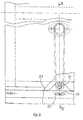
- FIG. 4 shows the drive system for the blades 6 and 7 which is housed in the thickness of the claw 1.
- This drive system consists of a motor pinion 250 driven by hydraulic device, a transmission chain 251, two pinions 252 and 253 integral with eccentrics 254 and 255 and a pinion 256 for winding the chain 251 on the two pinions 252 and 253.
- the two pinions 252 and 253 are arranged on either side of the plane 257 passing through the axis of the driving pinion 250 and the winding pinion 256.
- the blades 6 and 7 have guides 258 and 259, U-shaped, open upwards, which receive the eccentrics 254 and 255.
- the pinions 252 and 253 are arranged in the lower part of the plate 260; the winding pinion 256 is disposed substantially in the center of the plate.
- the space between the two pinions 252 and 253 is of the same order as the outside diameter of the winding pinion 256.
- the thickness of the pinions 252, 253 with their eccentrics 254, 255, is reduced to the maximum to allow their integration into the tapered lower part of the claw housing.
- the travel of each blade 6 and 7 is substantially greater than the pitch of their teeth; at the end of travel, the ends of the blades 6 and 7 are offset by a dimension substantially equal to twice the pitch P, which in fact allows, for cutting, a relative overlap of two teeth, relative to each other .
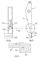
- the claw 1, shown in FIG. 5, comprises a rotary disc 101 disposed laterally in the lower part and against the box 5.
- the disc extends beyond each side of the box 5, thus achieving a vertical lateral cutout, on either side of the plane front cutting which is made by means of the knife 100.
- the disc 101 comprises, depending on the ensiled products, a smooth or serrated periphery: the periphery can cooperate with a counter-iron which permanently cleans the disc whose speed of rotation is around 200 rpm.
- the disc 101 is driven, directly, by a hydraulic motor I02, FIG. 6, housed in the thickness of the box 5 of the claw 1.
- This hydraulic motor 102 is more particularly housed in the lateral upright 103 of the claw 1.
- the axis of rotation 104 of the hydraulic motor 102 and of the disc 101 is arranged clearly above the upper edge 105 of the blades 6 and 7, at a distance slightly greater than the radius of the disc 101, to avoid interference between the ends of the blades 6 and 7 and the disc 101.
- the periphery of the disc 101 can however be placed at the edge of the knife 100; in this case, the blades 6 and 7 must not protrude from the box 5.
- FIG. 7 shows the cutting fronts obtained by the knife 100, on the one hand, and the disc 101 on the other hand, on a silo 106 of product of the corn or grass type.
- the knife 100 produces a vertical cutting front 107 whose dimension is at best equal to the length of said knife 100.
- the disc 101 produces a lateral cutting front 108, vertical and perpendicular to the cutting front 107 of the knife 100.
- This cutting front lateral section 108 is divided into two parts: a part which constitutes a waiting cutout in the silo; it only appears in the form of a line 109, and a portion 110 which constitutes the visible lateral cutting front.
- the cutting front 108 has a dimension of the order of the diameter of the disc 101.
- the cutting line 110 visible on the silo 106 corresponds to the trace of the projecting part of the disc 101, in front of the box 5 of the claw 1.
- the combination of the knife 100 and the disc 101 allows the cutting of product packages. It is however possible to take, depending on the stroke of the claw 1, several successive packages, without moving the bucket.
- the stroke of the claw 1 can be improved by an elongation of the operating arm 2; in this case the space between the claw and the entrance of the bucket is filled by side cheeks in the shape of a vee pointing downwards, and arranged on the claw, when said claw is placed in the door position to close the clamshell .
- the teeth of the blade 6, shown in Figure 8, consists of teeth 201, double-edged 202 and 203, and they are sharpened.
- the sharpening zone 204 between two teeth is continuous and the slope of this zone 204 is of the order of 45 °.
- the angle of attack 205 of the cutting edge 202, with the cutting front 206 of the product is an acute angle between 30 and 45 °; it is in the example of Figure 8, of the order of 40 °.
- the angle of attack 207 of the shearing edge 203, with the cutting edge 206 is an obtuse angle, between 95 and 120 °; it is, in the example of Figure 1, of the order of 105 °. Given the angle of attack obtained, the blade tends to advance automatically into the product to be cut.
- the pitch P, between two consecutive teeth, is substantially equal to the stroke C of the blade.
- the teeth of the blade 7 disposed on the back of the blade 6 is identical to that of said blade 6.
- the two blades 6 and 7 are movable, one with respect to the other and both move alternately, in opposite directions .
- the teeth 201 of the blade 6 and 208 of the blade 7 are in the opposite direction; they thus allow shearing of the products between the cutting edges 203 and 209 of the teeth 201 and 208, respectively.
- the teeth 201 and 208 tend to penetrate into the product.
- the cutting edges 202 and 210 of the teeth 201 and 208, respectively, ensure a simple cutting of the product.
- FIG 9 shows one of the blades used.
- This blade 6 has, on one half of its length, teeth 201 inclined in one direction and, on the other half of its length, teeth 211 identical to the teeth 201, except that they are inclined in the other direction.
- the teeth 201 and 211 of the blade 6 are divergent; the median axes 212 of the teeth 201 and the median axes 213 of the teeth 211 intersect above the cutting front 206 of the product. These teeth 201 and 211 are arranged symmetrically with respect to the median axis 214 of the blade 6.
- This tooth 215 comprises, on the one hand, two cutting edges 218 and 219, symmetrical, with respect to the median axis 214 of the blade 6 corresponding to the cutting edge 203 and, on the other hand, two cutting portions 220 and 221 corresponding to cutting edge 202.
- Figure 10 shows the other blade 7, used in cooperation with the blade 6, Figure 9; the two blades 6 and 7 being arranged back to back.
- the blade 7 has, on one half of its length, teeth 208 inclined in one direction and, on the other half, teeth 222 inclined in the other direction.
- the teeth 208 and 222 of the blade 7 are convergent; the median axes 223 of the teeth 208 and the median axes 224 of the teeth 222, intersect below the cutting front 206 of the product.
- the teeth 208 and 222 are arranged symmetrically with respect to the median axis 225 of the blade 7.
- An empty space 226 separates, in the center, the teeth 208 and 222, arranged at mid-length.
- the distance between the points 227 and 228 of the teeth 208 and 222 arranged in the center is substantially equal to one and a half times the pitch P.
- the empty space 226 is in the form of a dovetail and the upper edge 229 is also sharp.
- the blade 6 can be 4 mm thick while the blade 7 is 6 mm thick for example.
- each blade 6 or 7 being the following, starting from the point: first a slope on the area 204, which results from the cutting of the teeth at 45 ° then, when the thickness is about a third, that is to say of the '' order of 2 mm, a gentler slope at an angle of the order of 10 to 15 ° relative to the vertical face and preferably 12 ° as shown in Figure 11.
Landscapes
- Life Sciences & Earth Sciences (AREA)
- Environmental Sciences (AREA)
- Filling Or Emptying Of Bunkers, Hoppers, And Tanks (AREA)
- Crushing And Pulverization Processes (AREA)
- Massaging Devices (AREA)
- Ship Loading And Unloading (AREA)
Priority Applications (2)
| Application Number | Priority Date | Filing Date | Title |
|---|---|---|---|
| AT85401250T ATE52155T1 (de) | 1984-06-25 | 1985-06-21 | Ladegeraet fuer siloentnahme- und -verteilergeraete. |
| EP89201807A EP0338653B1 (de) | 1984-06-25 | 1985-06-21 | Ladegerät mit einer seitlich schneidenden Vorrichtung für Siloentnahme- und Verteilergeräte |
Applications Claiming Priority (6)
| Application Number | Priority Date | Filing Date | Title |
|---|---|---|---|
| FR8410181A FR2566229B1 (fr) | 1984-06-25 | 1984-06-25 | Perfectionnement aux desileuses distributrices et plus particulierement au dispositif de chargement |
| FR8410181 | 1984-06-25 | ||
| FR8418000A FR2573280B2 (fr) | 1984-11-21 | 1984-11-21 | Perfectionnement au dispositif de decoupage de produits ensiles monte sur une desileuse distributrice |
| FR8418001A FR2573281B2 (fr) | 1984-11-21 | 1984-11-21 | Perfectionnement au dispositif de chargement de produits ensiles monte sur une desileuse distributrice |
| FR8418001 | 1984-11-21 | ||
| FR8418000 | 1984-11-21 |
Related Child Applications (2)
| Application Number | Title | Priority Date | Filing Date |
|---|---|---|---|
| EP89201807A Division EP0338653B1 (de) | 1984-06-25 | 1985-06-21 | Ladegerät mit einer seitlich schneidenden Vorrichtung für Siloentnahme- und Verteilergeräte |
| EP89201807.8 Division-Into | 1985-06-21 |
Publications (2)
| Publication Number | Publication Date |
|---|---|
| EP0169759A1 true EP0169759A1 (de) | 1986-01-29 |
| EP0169759B1 EP0169759B1 (de) | 1990-04-25 |
Family
ID=27251226
Family Applications (1)
| Application Number | Title | Priority Date | Filing Date |
|---|---|---|---|
| EP85401250A Expired - Lifetime EP0169759B1 (de) | 1984-06-25 | 1985-06-21 | Ladegerät für Siloentnahme- und -verteilergeräte |
Country Status (4)
| Country | Link |
|---|---|
| EP (1) | EP0169759B1 (de) |
| AT (2) | ATE52155T1 (de) |
| DE (4) | DE338653T1 (de) |
| ES (1) | ES8608786A1 (de) |
Cited By (2)
| Publication number | Priority date | Publication date | Assignee | Title |
|---|---|---|---|---|
| FR2634347A1 (fr) * | 1988-07-22 | 1990-01-26 | Lidel Josef | Dispositif de prelevement pour separer et ramasser du fourrage |
| FR2644668A1 (fr) * | 1989-03-23 | 1990-09-28 | Lucas Georges Ets | Dispositif de coupe pour desileuse, et dispositif de coupe rotatif pour vegetaux, notamment ensiles |
Families Citing this family (1)
| Publication number | Priority date | Publication date | Assignee | Title |
|---|---|---|---|---|
| CN110383990B (zh) * | 2019-08-26 | 2021-04-06 | 新疆农业大学 | 一种畜牧养殖用牧草加工细化装置 |
Citations (8)
| Publication number | Priority date | Publication date | Assignee | Title |
|---|---|---|---|---|
| US2733565A (en) * | 1956-02-07 | Lawn mower | ||
| FR1430701A (fr) * | 1964-04-23 | 1966-03-04 | Harder Georg Maschinenfabrik | Fraise mobile pour la reprise par voie entièrement mécanique de produits ensilés |
| FR2148060A1 (de) * | 1971-07-30 | 1973-03-16 | Schaffer Heinrich | |
| FR2174338A5 (de) * | 1972-02-29 | 1973-10-12 | Teebken Wilhelm | |
| US4133236A (en) * | 1977-11-29 | 1979-01-09 | Gerber Garment Technology, Inc. | Sharpenable cutting blade with skew-cut notches for use in sheet material cutting apparatus |
| EP0013058A1 (de) * | 1978-12-27 | 1980-07-09 | Joris Jan Thomas | Hebezeug und Schneideinrichtung dafür |
| DE2935870A1 (de) * | 1979-09-05 | 1981-04-02 | Walter 8311 Pauluszell Föckersperger | Vorrichtung zur entnahme von silage |
| FR2501130A1 (fr) * | 1981-03-06 | 1982-09-10 | Cacquevel Bernard | Remorque distributrice et melangeuse |
Family Cites Families (6)
| Publication number | Priority date | Publication date | Assignee | Title |
|---|---|---|---|---|
| DE2032215A1 (de) * | 1970-06-30 | 1972-01-05 | Teebken, Wilhelm, 2900 Oldenburg | Silageschneidvorrichtung |
| DE2142163A1 (de) * | 1971-08-23 | 1973-03-08 | Wilhelm Teebken | Silageschneidvorrichtung |
| US3830438A (en) * | 1972-01-20 | 1974-08-20 | Hesston Corp | Machine for feeding materials from a stack |
| DE2810366C2 (de) * | 1978-03-10 | 1979-09-06 | Josef Brunnhuber Ohg, 8900 Augsburg | Selbstladendes und -entladendes Futtertransportgerät |
| EP0090906B1 (de) * | 1982-04-01 | 1986-07-30 | Mullos B.V. Trioliet | Schneidorgan zum Schneiden von Silagegut |
| DE3279384D1 (en) * | 1982-09-03 | 1989-03-02 | Trioliet Mullos | Silage cutter and an agricultural machine having a loader implement including a similar silage cutter |
-
1985
- 1985-06-21 DE DE198989201807T patent/DE338653T1/de active Pending
- 1985-06-21 DE DE198585401250T patent/DE169759T1/de active Pending
- 1985-06-21 DE DE8585401250T patent/DE3577263D1/de not_active Expired - Fee Related
- 1985-06-21 AT AT85401250T patent/ATE52155T1/de not_active IP Right Cessation
- 1985-06-21 DE DE3587803T patent/DE3587803T2/de not_active Expired - Fee Related
- 1985-06-21 EP EP85401250A patent/EP0169759B1/de not_active Expired - Lifetime
- 1985-06-24 ES ES544490A patent/ES8608786A1/es not_active Expired
-
1989
- 1989-07-07 AT AT8989201807T patent/ATE104505T1/de not_active IP Right Cessation
Patent Citations (8)
| Publication number | Priority date | Publication date | Assignee | Title |
|---|---|---|---|---|
| US2733565A (en) * | 1956-02-07 | Lawn mower | ||
| FR1430701A (fr) * | 1964-04-23 | 1966-03-04 | Harder Georg Maschinenfabrik | Fraise mobile pour la reprise par voie entièrement mécanique de produits ensilés |
| FR2148060A1 (de) * | 1971-07-30 | 1973-03-16 | Schaffer Heinrich | |
| FR2174338A5 (de) * | 1972-02-29 | 1973-10-12 | Teebken Wilhelm | |
| US4133236A (en) * | 1977-11-29 | 1979-01-09 | Gerber Garment Technology, Inc. | Sharpenable cutting blade with skew-cut notches for use in sheet material cutting apparatus |
| EP0013058A1 (de) * | 1978-12-27 | 1980-07-09 | Joris Jan Thomas | Hebezeug und Schneideinrichtung dafür |
| DE2935870A1 (de) * | 1979-09-05 | 1981-04-02 | Walter 8311 Pauluszell Föckersperger | Vorrichtung zur entnahme von silage |
| FR2501130A1 (fr) * | 1981-03-06 | 1982-09-10 | Cacquevel Bernard | Remorque distributrice et melangeuse |
Cited By (3)
| Publication number | Priority date | Publication date | Assignee | Title |
|---|---|---|---|---|
| FR2634347A1 (fr) * | 1988-07-22 | 1990-01-26 | Lidel Josef | Dispositif de prelevement pour separer et ramasser du fourrage |
| FR2644668A1 (fr) * | 1989-03-23 | 1990-09-28 | Lucas Georges Ets | Dispositif de coupe pour desileuse, et dispositif de coupe rotatif pour vegetaux, notamment ensiles |
| EP0392890A1 (de) * | 1989-03-23 | 1990-10-17 | Etablissements Lucas G. | Silofutterschneider und Schneidvorrichtung für Futter, insbesondere Silofutter |
Also Published As
| Publication number | Publication date |
|---|---|
| DE169759T1 (de) | 1986-10-16 |
| DE338653T1 (de) | 1990-03-22 |
| ES8608786A1 (es) | 1986-07-16 |
| ES544490A0 (es) | 1986-07-16 |
| DE3577263D1 (de) | 1990-05-31 |
| DE3587803T2 (de) | 1994-10-13 |
| EP0169759B1 (de) | 1990-04-25 |
| ATE104505T1 (de) | 1994-05-15 |
| DE3587803D1 (de) | 1994-05-26 |
| ATE52155T1 (de) | 1990-05-15 |
Similar Documents
| Publication | Publication Date | Title |
|---|---|---|
| EP1361786B1 (de) | Viehfuttermisch- und verteilanlage | |
| FR2726966A1 (fr) | Dispositif de coupe et de transport pour des produits agricoles a tiges | |
| EP0384791B1 (de) | Verteileinrichtung für pflanzliches Material wie Futter oder Stroh | |
| EP0169759B1 (de) | Ladegerät für Siloentnahme- und -verteilergeräte | |
| FR2492218A1 (fr) | Machine pour hacher les plantes fourrageres | |
| EP0493229B1 (de) | Abfalltrennvorrichtung für Kartonbögen und ähnliche Materialien | |
| FR2581916A1 (fr) | Dispositif de decoupe, notamment entre deux zones de durete differente | |
| EP0338653B1 (de) | Ladegerät mit einer seitlich schneidenden Vorrichtung für Siloentnahme- und Verteilergeräte | |
| EP1903855B1 (de) | Vorrichtung zum beschneiden und zerkleinern von pflanzen | |
| EP3909430A1 (de) | Vorrichtung zum portionieren von würsten | |
| FR2509570A1 (fr) | Dispositif destine a debiter des balles et des bottes de paille ou de fourrage | |
| EP0392890B1 (de) | Silofutterschneider und Schneidvorrichtung für Futter, insbesondere Silofutter | |
| FR2596945A1 (fr) | Dispositif pour le prelevement d'une matiere compactee, et vehicule equipe dudit dispositif | |
| EP2260984B1 (de) | Methode und Vorrichtung zum Schneiden von Brot | |
| EP0315521A1 (de) | Schneid- und Sammelvorrichtung für Weinreben | |
| EP0570253B1 (de) | Vorrichtung zum Halten, Verschliessen und eventuell Trennen von Wursthüllen | |
| FR2573281A2 (fr) | Perfectionnement au dispositif de chargement de produits ensiles monte sur une desileuse distributrice | |
| EP0543688B1 (de) | Silofutterschneider | |
| EP0660997B1 (de) | Futter- oder Silageverteilmaschine | |
| FR2546207A1 (fr) | Dispositif pour le prelevement et le chargement de matiere compactee | |
| EP2732695A1 (de) | Landwirtschaftliche Maschine zum Auftrennen von Stroh- oder Heuballen | |
| FR2509957A1 (fr) | Machine pour le prelevement de blocs de fourrage dans un silo | |
| FR2573614A1 (fr) | Perfectionnement au dispositif de chargement de la benne d'une desileuse distributrice. | |
| FR2634347A1 (fr) | Dispositif de prelevement pour separer et ramasser du fourrage | |
| FR2684036A1 (fr) | Machine pour le tranchage automatique de produits alimentaires. |
Legal Events
| Date | Code | Title | Description |
|---|---|---|---|
| PUAI | Public reference made under article 153(3) epc to a published international application that has entered the european phase |
Free format text: ORIGINAL CODE: 0009012 |
|
| AK | Designated contracting states |
Designated state(s): AT BE CH DE FR GB IT LI LU NL SE |
|
| 17P | Request for examination filed |
Effective date: 19860618 |
|
| TCNL | Nl: translation of patent claims filed | ||
| DET | De: translation of patent claims | ||
| 17Q | First examination report despatched |
Effective date: 19870821 |
|
| GRAA | (expected) grant |
Free format text: ORIGINAL CODE: 0009210 |
|
| ITF | It: translation for a ep patent filed | ||
| AK | Designated contracting states |
Kind code of ref document: B1 Designated state(s): AT BE CH DE FR GB IT LI LU NL SE |
|
| PG25 | Lapsed in a contracting state [announced via postgrant information from national office to epo] |
Ref country code: SE Effective date: 19900425 |
|
| REF | Corresponds to: |
Ref document number: 52155 Country of ref document: AT Date of ref document: 19900515 Kind code of ref document: T |
|
| XX | Miscellaneous (additional remarks) |
Free format text: TEILANMELDUNG 89201807.8 EINGEREICHT AM 21/06/85. |
|
| REF | Corresponds to: |
Ref document number: 3577263 Country of ref document: DE Date of ref document: 19900531 |
|
| GBT | Gb: translation of ep patent filed (gb section 77(6)(a)/1977) | ||
| PLBE | No opposition filed within time limit |
Free format text: ORIGINAL CODE: 0009261 |
|
| STAA | Information on the status of an ep patent application or granted ep patent |
Free format text: STATUS: NO OPPOSITION FILED WITHIN TIME LIMIT |
|
| 26N | No opposition filed | ||
| EPTA | Lu: last paid annual fee | ||
| PGFP | Annual fee paid to national office [announced via postgrant information from national office to epo] |
Ref country code: AT Payment date: 19970611 Year of fee payment: 13 |
|
| PGFP | Annual fee paid to national office [announced via postgrant information from national office to epo] |
Ref country code: GB Payment date: 19970612 Year of fee payment: 13 |
|
| PGFP | Annual fee paid to national office [announced via postgrant information from national office to epo] |
Ref country code: CH Payment date: 19970630 Year of fee payment: 13 |
|
| PGFP | Annual fee paid to national office [announced via postgrant information from national office to epo] |
Ref country code: LU Payment date: 19970715 Year of fee payment: 13 |
|
| PG25 | Lapsed in a contracting state [announced via postgrant information from national office to epo] |
Ref country code: LU Free format text: LAPSE BECAUSE OF NON-PAYMENT OF DUE FEES Effective date: 19980621 Ref country code: GB Free format text: LAPSE BECAUSE OF NON-PAYMENT OF DUE FEES Effective date: 19980621 Ref country code: AT Free format text: LAPSE BECAUSE OF NON-PAYMENT OF DUE FEES Effective date: 19980621 |
|
| PG25 | Lapsed in a contracting state [announced via postgrant information from national office to epo] |
Ref country code: LI Free format text: LAPSE BECAUSE OF NON-PAYMENT OF DUE FEES Effective date: 19980630 Ref country code: CH Free format text: LAPSE BECAUSE OF NON-PAYMENT OF DUE FEES Effective date: 19980630 |
|
| GBPC | Gb: european patent ceased through non-payment of renewal fee |
Effective date: 19980621 |
|
| REG | Reference to a national code |
Ref country code: CH Ref legal event code: PL |
|
| PGFP | Annual fee paid to national office [announced via postgrant information from national office to epo] |
Ref country code: NL Payment date: 19990603 Year of fee payment: 15 |
|
| PGFP | Annual fee paid to national office [announced via postgrant information from national office to epo] |
Ref country code: DE Payment date: 19990608 Year of fee payment: 15 |
|
| PGFP | Annual fee paid to national office [announced via postgrant information from national office to epo] |
Ref country code: FR Payment date: 19990625 Year of fee payment: 15 |
|
| PGFP | Annual fee paid to national office [announced via postgrant information from national office to epo] |
Ref country code: BE Payment date: 19990809 Year of fee payment: 15 |
|
| PG25 | Lapsed in a contracting state [announced via postgrant information from national office to epo] |
Ref country code: BE Free format text: LAPSE BECAUSE OF NON-PAYMENT OF DUE FEES Effective date: 20000630 |
|
| BERE | Be: lapsed |
Owner name: ETS LUCAS G Effective date: 20000630 |
|
| PG25 | Lapsed in a contracting state [announced via postgrant information from national office to epo] |
Ref country code: NL Free format text: LAPSE BECAUSE OF NON-PAYMENT OF DUE FEES Effective date: 20010101 |
|
| PG25 | Lapsed in a contracting state [announced via postgrant information from national office to epo] |
Ref country code: FR Free format text: LAPSE BECAUSE OF NON-PAYMENT OF DUE FEES Effective date: 20010228 |
|
| NLV4 | Nl: lapsed or anulled due to non-payment of the annual fee |
Effective date: 20010101 |
|
| REG | Reference to a national code |
Ref country code: FR Ref legal event code: ST |
|
| PG25 | Lapsed in a contracting state [announced via postgrant information from national office to epo] |
Ref country code: DE Free format text: LAPSE BECAUSE OF NON-PAYMENT OF DUE FEES Effective date: 20010403 |