EP0169792A1 - Capsule réceptrice téléphonique compatible avec les prothèses auditives pour malentendants - Google Patents
Capsule réceptrice téléphonique compatible avec les prothèses auditives pour malentendants Download PDFInfo
- Publication number
- EP0169792A1 EP0169792A1 EP85420131A EP85420131A EP0169792A1 EP 0169792 A1 EP0169792 A1 EP 0169792A1 EP 85420131 A EP85420131 A EP 85420131A EP 85420131 A EP85420131 A EP 85420131A EP 0169792 A1 EP0169792 A1 EP 0169792A1
- Authority
- EP
- European Patent Office
- Prior art keywords
- coil
- auxiliary
- main coil
- housing
- assembly
- Prior art date
- Legal status (The legal status is an assumption and is not a legal conclusion. Google has not performed a legal analysis and makes no representation as to the accuracy of the status listed.)
- Withdrawn
Links
Images
Classifications
-
- H—ELECTRICITY
- H04—ELECTRIC COMMUNICATION TECHNIQUE
- H04M—TELEPHONIC COMMUNICATION
- H04M1/00—Substation equipment, e.g. for use by subscribers
- H04M1/247—Telephone sets including user guidance or feature selection means facilitating their use
- H04M1/2474—Telephone terminals specially adapted for disabled people
- H04M1/2475—Telephone terminals specially adapted for disabled people for a hearing impaired user
-
- H—ELECTRICITY
- H04—ELECTRIC COMMUNICATION TECHNIQUE
- H04M—TELEPHONIC COMMUNICATION
- H04M1/00—Substation equipment, e.g. for use by subscribers
- H04M1/02—Constructional features of telephone sets
- H04M1/21—Combinations with auxiliary equipment, e.g. with clocks or memoranda pads
- H04M1/215—Combinations with auxiliary equipment, e.g. with clocks or memoranda pads by non-intrusive coupling means, e.g. acoustic couplers
-
- H—ELECTRICITY
- H04—ELECTRIC COMMUNICATION TECHNIQUE
- H04R—LOUDSPEAKERS, MICROPHONES, GRAMOPHONE PICK-UPS OR LIKE ACOUSTIC ELECTROMECHANICAL TRANSDUCERS; ELECTRIC HEARING AIDS; PUBLIC ADDRESS SYSTEMS
- H04R9/00—Transducers of moving-coil, moving-strip, or moving-wire type
- H04R9/06—Loudspeakers
- H04R9/063—Loudspeakers using a plurality of acoustic drivers
Definitions
- the present invention relates to telephone receiver capsules, generally comprising a box containing a transducer for transforming into sound vibrations the electrical signals conveyed on its input terminals by a supply line.
- the transducers currently used for reception in telephony operate according to two known principles: the electrodynamic principle - the electromagnetic principle.
- Electromagnetic transducers or variable reluctance transducers, have been specially adapted for telephony for a long time. However, they have drawbacks, particularly regarding the quality of sound reproduction, and are gradually tending to be replaced by better quality transducers.
- the electrodynamic transducers of more recent application in telephony for questions of technology and optimization, group together the transducers known as moving coil. These transducers are advantageous insofar as their manufacture is simple and, above all, where their electroacoustic performances are better than those of the other transducers.
- Hearing aids for the hearing impaired are designed to amplify the acoustic vibrations received and make them perceptible by the ear.
- certain prostheses include an adjustment device which, in the "T" position, makes them capable of picking up a magnetic field such as the magnetic field produced by a telephone capsule transducer. These prostheses work correctly when the transducer is of the electromagnetic type.
- the object of the present invention is in particular to provide improvements to telephone reception capsules making it possible to produce, whatever the type of transducer used, a magnetic field sufficient to be picked up by a hearing aid.
- the invention makes it possible to produce a transducer capsule, in particular of the electrodynamic type, having in itself the function of magnetic radiation for hearing aids, without requiring the connection of an external device.
- Another object of the invention is to carry out these improvements at a lower cost, and in particular without unduly complicating the operations for manufacturing the capsule.
- Another object of the invention is to make these improvements without significantly disturbing the efficiency of the transducer.
- the present invention provides the capsule with an internal auxiliary device, powered by the electrical signals of the power line, and producing an auxiliary magnetic field modulated by these signals and capable of be picked up outside the capsule by a hearing aid hearing impaired.
- the auxiliary device is connected to the supply line and is arranged in the case so that the auxiliary magnetic field which it produces is in phase with the magnetic field possibly produced by the transducer .
- the auxiliary device is an auxiliary coil mounted fixed in the housing, and formed of a conductive wire wound around an insulating tubular frame secured to the housing, the ends of the wire being electrically connected in series or in parallel with the transducer.
- an electrodynamic type transducer comprising a central membrane secured to a main coil connected to the supply line by flexible wires, the main membrane-coil assembly being suspended in the housing by an elastic annular peripheral suspension connecting the circular periphery of the membrane and a rigid peripheral support secured to the housing, the main coil-membrane-suspension-support assembly rigid forms a sub-assembly called mobile assembly, mounted separately and then attached in the case; the auxiliary coil is fixed on the rigid support and constitutes, with the moving part, a compact sub-assembly.
- Figures 1 and 2 illustrate an embodiment in which the capsule 1 is provided with a transducer 2 of the electrodynamic type.
- the capsule 1 comprises a case 3 made of non-magnetic material, open at one end 4, the end 4 being closed successively by the movable assembly 5 and by a mechanical protection cover 15 made of non-magnetic material.
- the moving element 5 comprises a central membrane 6, integral with a main coil 7 connected to two terminals of the shoemaker by flexible wires not shown in the figures.
- the central membrane 6 - main coil 7 assembly is held suspended in the housing 3 by an elastic annular peripheral suspension 8, formed of a membrane with concentric undulations, the suspension connecting the circular periphery of the central membrane 6 and a rigid peripheral support 9 itself secured along its periphery to the housing 3.
- the main coil 7 partially penetrates into the air gap 10 of a permanent magnet 11 disposed inside the case 3, as shown in FIG. 1.
- the magnetic field radiated by the main coil 7 is insufficient to excite a hearing aid.
- an auxiliary coil 12 fixedly mounted, is also inserted in the case 3. in the case, formed of a conductive wire wound around an insulating tubular frame 13 secured to the case 3. The ends of the wire of the auxiliary coil 12 are electrically connected in series or in parallel with the main coil 7.
- the auxiliary coil 12 produces a magnetic field, image of the electrical signals received by the capsule, and capable of radiating out of the housing 3 to be picked up by a hearing aid for the hearing impaired.
- the auxiliary coil 12 is arranged in the housing 3 concentric with the main coil 7, that is to say admitting the same axis of symmetry I-I.
- the auxiliary coil 12 is electrically connected with respect to the main coil 7 in a direction ensuring the production of a magnetic field in phase with the magnetic field produced by the main coil 7. In fact, if the connection is opposite, magnetic losses appear which are functions of the two radiated fields, losses caused by the contradictory radiations.
- auxiliary coil 12 it is particularly important to be able to introduce the auxiliary coil 12 at the same time as the manufacture of the capsule 1. In fact, it is then possible to identify the terminals of the various coils, and thus to ensure that the connections are correct in order to produce magnetic fields in phase.
- the double coil capsule certainly provides optimum performance due to this identification of the poles during manufacture.
- the connection of the coils can also be done by simple soldering, without the need for additional connectors, which tends to significantly reduce the cost of the device.
- the main coil 7 - membrane 6 - suspension 8 - rigid support 9 assembly forms a sub-assembly called mobile assembly 5.
- the mobile assembly during the manufacture of the capsule, is mounted separately and is attached then in the case 3. It is then preferable to fix the auxiliary coil 12 directly on the rigid support 9, which allows the assembly of this auxiliary coil 12 during the manufacture of the moving element 5.
- the auxiliary coil 12 forms thus with the moving assembly 5 a compact sub-assembly.
- the frame 13 of the auxiliary coil 12 is secured to the rigid support 9. It is possible to wind the wire in a single operation, the same wire forming on the one hand the main coil 7, and on the other hand the auxiliary coil 12, which avoids at the same time the location of the terminals of the two coils.
- a rigid peripheral support 9 comprising a shoulder 14 forming a cylindrical outer surface to act as a frame and to receive the wire from the auxiliary coil 12.
- the additional cost achieved by the addition of an additional copper mass represents a small percentage of the price of the transducer. This increase in cost is reasonable taking into account the technical advantages acquired. It thus becomes possible to manufacture, with modern technologies, efficient transducers for telephony and compatible with hearing aids for the hearing impaired.
- the auxiliary coil must not disturb the operation of the main coil. In particular, care should be taken to prevent the insertion of the auxiliary coil from causing the acoustic efficiency of the transducer to drop. This can be done by connecting the main coil and the auxiliary coil electrically in parallel, and choosing an auxiliary coil which has an electrical impedance at least eight to ten times greater than that of the main coil.
- the main coil 7 and the auxiliary coil 12 are connected in series; in this case, the auxiliary coil 12 has an electrical impedance at least eight to ten times lower than that of the main coil 7.
Landscapes
- Engineering & Computer Science (AREA)
- Signal Processing (AREA)
- Physics & Mathematics (AREA)
- Acoustics & Sound (AREA)
- Health & Medical Sciences (AREA)
- Otolaryngology (AREA)
- Computer Vision & Pattern Recognition (AREA)
- Human Computer Interaction (AREA)
- Telephone Set Structure (AREA)
Abstract
La capsule (1) comprend un transducteur de type électrodynamique (2) avec une membrane centrale (6) solidaire d'une bobine principale (7), l'ensemble étant suspendu dans le boîtier (3). Une bobine auxiliaire (12) fixe, connectée en parallèle sur la bobine principale (7), et montée fixe dans le boîtier (3), produit un champ magnétique auxiliaire susceptible d'être capté par une prothèse auditive pour malentendant.
Description
- La présente invention concerne les capsules réceptrices téléphoniques, comprenant généralement un boitier renfermant un transducteur pour transformer en vibrations sonores les signaux électriques acheminés sur ses bornes d'entrée par une ligne d'alimentation.
- Les transducteurs actuellement utilisés pour la réception en téléphonie fonctionnent suivant deux principes connus : le principe électrodynamique - le principe électromagnétique.
- Les transducteurs électromagnétiques, ou transducteurs à réluctance variable, sont spécialement adaptés à la téléphonie depuis longtemps. Ils comportent toutefois des inconvénients, notamment concernant la qualité de reproduction sonore, et tendent peu à peu à être remplacés par des transducteurs de meilleure qualité.
- Les transducteurs électrodynamiques, d'application plus récente dans la téléphonie pour des questions de technologie et d!optimisation, regroupent les transducteurs dits à bobine mobile. Ces transducteurs sont intéressants dans la mesure où leur fabrication est simple et, surtout, où leurs performances électroacoustiques sont meilleures que celles des autres transducteurs.
- Les prothèses auditives pour malentendants sont conçues pour amplifier les vibrations accoustiques reçues et les rendre perceptibles par l'oreille. Toutefois, certaines prothèses comportent un dispositif de règlage qui, en position "T", les rend aptes à capter un champ magnétique tel que le champ magnétique produit par un transducteur de capsule téléphonique. Ces prothèses fonctionnent correctement lorsque le transducteur est de type électromagnétique.
- Par contre, le champ magnétique rayonné par la bobine d'un capteur électrodynamique est limité, voire insuffisant pour assurer le fonctionnement correct d'une prothèse auditive. Cet inconvénient, fondamental pour la téléphonie, suffit à repousser les transducteurs électrodynamiques pour ne retenir que les électromagnétiques, parfaitement adaptés à cette fonction.
- La présente invention a notamment pour objet d'apporter des perfectionnements aux capsules réceptrices téléphoniques permettant de produire, quel que soit le type de transducteur utilisé, un champ magnétique suffisant pour être capté par une prothèse auditive.
- En particulier, l'invention permet de réaliser une capsule à transducteur notamment de type électrodynamique présentant en elle-même la fonction de rayonnement magnétique pour prothèses auditives, sans nécessiter la connexion d'un dispositif extérieur.
- Cela constitue un avantage certain, car les connexions de dispositifs extérieurs éventuels nécessitent des modifications importantes des connecteurs rapides habituellement utilisés, et ces connexions sont rarement compatibles. En outre, une connexion d'un dispositif en série nécessiterait l'adjonction d'une troisième borne extérieure. Au contraire, le perfectionnement selon l'invention évite tous les problèmes liés aux connecteurs.
- Un autre objet de l'invention est de réaliser ces perfectionnements à moindre coût, et notamment sans compliquer exagérément les opérations de fabrication de la capsule.
- Un autre objet de l'invention est de réaliser ces perfectionnements sans perturber de façon sensible l'efficacité du transducteur.
- Pour atteindre ces objets ainsi que d'autres, la présente invention prévoit de munir la capsule d'un dispositif auxiliaire interne, alimenté par les signaux électriques de la ligne d'alimentation, et produisant un champ magnétique auxiliaire modulé par ces signaux et susceptible d'être capté à l'extérieur de la capsule par une prothèse auditive de malentendant.
- Selon une autre caractéristique de l'invention, le dispositif auxiliaire est connecté à la ligne d'alimentation et est disposé dans le bottier de telle manière que le champ magnétique auxiliaire qu'il produit soit en phase avec le champ magnétique éventuellement produit par le transducteur.
- Selon une autre caractéristique, le dispositif auxiliaire est une bobine auxiliaire montée fixe dans le boîtier, et formée d'un fil conducteur enroulé autour d'un cadre tubulaire isolant solidaire du boitier, les extrémités du fil étant connectées électriquement en série ou en parallèle avec le transducteur.
- Selon une caractéristique particulièrement intéressante pour abaisser le coût de production, et adaptée à l'utilisation d'un transducteur de type électrodynamique, comprenant une membrane centrale solidaire d'une bobine principale connectée à la ligne d'alimentation par des fils souples, l'ensemble membrane-bobine principale étant suspendu dans le boîtier par une suspension périphérique annulaire élastique reliant le pourtour circulaire de la membrane et un support périphérique rigide solidarisé au boitier, l'ensemble bobine principale- membrane-suspension-support rigide forme un sous-ensemble appelé équipage mobile, monté à part et rapporté ensuite dans le boitier; la bobine auxiliaire est fixée sur le support rigide et constitue, avec l'équipage mobile, un sous-ensemble compact.
- D'autres objets, caractéristiques et avantages de la présente invention, ressortiront de la description suivante d'un mode de réalisation particulier, faite en relation avec les figures jointes, parmi lesquelles :
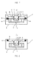
- - la figure 1 représente une vue en coupe d'une capsule téléphonique selon la présente invention ; et
- - la figure 2 représente une vue partielle en coupe selon un mode de réalisation préféré.
- Les figures 1 et 2 illustrent un mode de réalisation dans lequel la capsule 1 est munie d'un transducteur 2 de type électrodynamique.
- La capsule 1 comprend un bottier 3 en matériau amagnétique, ouvert à une extrémité 4, l'extrémité 4 étant fermée successivement par l'équipage mobile 5 et par un couvercle de protection mécanique 15 en matériau amagnétique. L'équipage mobile 5 comprend une membrane centrale 6, solidaire d'une bobine principale 7 connectée à deux bornes du bottier par des fils souples non représentés sur les figures. L'ensemble membrane centrale 6 - bobine principale 7 est maintenu suspendu dans le boîtier 3 par une suspension périphérique annulaire élastique 8, formée d'une membrane à ondulations concentriques, la suspension reliant le pourtour circulaire de la membrane centrale 6 et un support périphérique rigide 9 lui-même solidarisé selon son pourtour au boîtier 3. La bobine principale 7 pénètre partiellement dans l'entrefer 10 d'un aimant permanent 11 disposé à l'intérieur du bottier 3, comme le représente la figure 1.
- Le champ magnétique rayonné par la bobine principale 7 est insuffisant pour exciter une prothèse auditive.
- Pour rendre la prothèse auditive sensible à la capsule 1, on insère en outre dans le bottier 3 une bobine auxiliaire 12, montée fixe dans le bottier, formée d'un fil conducteur enroulé autour d'un cadre tubulaire isolant 13 solidaire du bottier 3. Les extrémités du fil de la bobine auxiliaire 12 sont connectés électriquement en série ou en parallèle avec la bobine principale 7. La bobine auxiliaire 12 produit un champ magnétique, image des signaux électriques reçus par la capsule, et susceptible de rayonner hors du boîtier 3 pour être capté par une prothèse auditive de malentendant.
- De façon préférée, la bobine auxiliaire 12 est disposée dans le boitier 3 de manière concentrique à la bobine principale 7, c'est-à-dire admettant le même axe de symétrie I-I. En outre, la bobine auxiliaire 12 est connectée électriquement par rapport à la bobine principale 7 selon un sens assurant la production d'un champ magnétique en phase avec le champ magnétique produit par la bobine principale 7. En effet, si le branchement est contraire, il apparaît des pertes magnétiques fonctions des deux champs rayonnés, pertes occasionnées par les rayonnements contradictoires.
- Il est particulièrement important de pouvoir introduire la bobine auxiliaire 12 au moment même de la fabrication de la capsule 1. En effet, il est alors possible de repérer les bornes des différentes bobines, et de s'assurer ainsi que les connections sont correctes pour produire des champs magnétiques en phase. La capsule à double bobine permet, à coup sûr, d'obtenir un rendement optimum du fait de ce repérage des pôles à la fabrication. La connection des bobines peut en outre se faire par simple soudure, sans nécessiter de connecteurs supplémentaires, ce qui tend à réduire sensiblement le coût du dispositif.
- Selon une disposition préférée, l'ensemble bobine principale 7 - membrane 6 - suspension 8 - support rigide 9 forme un sous ensemble appelé équipage mobile 5. L'équipage mobile, lors de la fabrication de la capsule, est monté à part et est rapporté ensuite dans le bottier 3. Il est alors préférable de fixer la bobine auxiliaire 12 directement sur le support rigide 9, ce qui permet l'assemblage de cette bobine auxilaire 12 lors de la fabrication de l'équipage mobile 5. La bobine auxiliaire 12 forme ainsi avec l'équipage mobile 5 un sous-ensemble compact. On solidarise pour cela le cadre 13 de la bobine auxiliaire 12 sur le support rigide 9. Il est possible de bobiner le fil en une seule opération, le même fil formant d'une part la bobine principale 7, et d'autre part la bobine auxiliaire 12, ce qui évite par la même occasion le repérage des bornes des deux bobines.
- Il est possible de simplifier la construction en prévoyant, comme le représente la figure 2, un support périphérique rigide 9 comportant un épaulement 14 formant une surface extérieure cylindrique pour faire office de cadre et recevoir le fil de la bobine auxiliaire 12. Le surcoût réalisé par l'adjonction d'une masse de cuivre supplémentaire représente un faible pourcentage du prix du transducteur. Cette augmentation de coût est raisonnable compte tenu des avantages techniques acquis. Il devient ainsi possible de fabriquer, avec des technologies modernes, des transducteurs performants pour la téléphonie et compatibles avec les prothèses auditives pour malentendants.
- La bobine auxiliaire ne doit pas perturber le fonctionnement de la bobine principale. En particulier, il convient d'éviter que l'insertion de la bobine auxiliaire ne fasse chuter l'efficacité acoustique du transducteur. On peut pour cela connecter la bobine principale et la bobine auxiliaire électriquement en parallèle, et choisir une bobine auxiliaire qui ait une impédance électrique au moins huit à dix fois supérieure à celle de la bobine principale.
- En alternative, la bobine principale 7 et la bobine auxiliaire 12 sont connectées en série ; dans ce cas, la bobine auxiliaire 12 a une impédance électrique au moins huit à dix fois inférieure à celle de la bobine principale 7.
- La présente invention n'est pas limitée aux modes de réalisation qui ont été explicitement décrits, mais elle en inclut les diverses variantes et généralisations contenues dans le domaine des revendications ci-après.
Claims (8)
1 - Capsule réceptrice téléphonique, comprenant un boîtier (3) renfermant un transducteur (2) pour transformer en vibrations sonores les signaux électriques acheminés sur ses bornes d'entrée par une ligne d'alimentation, caractérisée en ce que le bottier est en matériau amagnétique, et en ce que la capsule comprend en outre un dipositif auxiliaire (12), disposé dans le boitier (3), alimenté par les signaux électriques de la ligne d'alimentation, et produisant un champ magnétique auxiliaire modulé par ces signaux et susceptible d'être capté à l'extérieur du boitier par une prothèse auditive de malentendant.
2 - Capsule réceptrice selon la revendication 1, caractérisée en ce que le dispositif auxiliaire (12) est connecté à la ligne d'alimentation et est disposé dans le boitier (3) de telle manière que le champ magnétique auxiliaire qu'il produit soit en phase avec le champ magnétique éventuellement produit par le transducteur (2).
3 - Capsule réceptrice selon la revendication 1, caractérisée en ce que le dispositif auxiliaire est une bobine auxiliaire (12) montée fixe dans le boîtier (3), et formée d'un fil conducteur enroulé autour d'un cadre tubulaire isolant (13) solidaire du boitier, les extrémités du fil étant connectées électriquement en série ou en parallèle avec le transducteur (2).
4 - Capsule réceptrice selon la revendication 3, dans laquelle le transducteur (2) est de type électrodynamique, comprenant une membrane centrale (6) solidaire d'une bobine principale (7) connectée à la ligne d'alimentation par des fils souples, l'ensemble membrane (6) - bobine principale (7) étant suspendu dans le boitier (3) par une suspension périphérique annulaire élastique (8) reliant le pourtour circulaire de la membrane (6) et un support périphérique rigide (9) solidarisé au boitier, la bobine (7) principale pénétrant partiellement dans l'entrefer (10) d'un aimant permanent (11), caractérisée en ce que :
- l'ensemble bobine principale (7) - membrane (6) - suspension (8) - support rigide (9) forme un sous-ensemble appelé équipage mobile (5), monté à part et rapporté ensuite dans le boîtier (3),
- la bobine auxiliaire (12) est fixée sur le support rigide (9) et constitue, avec l'équipage mobile (5), un sous-ensemble compact.
5 - Capsule réceptrice selon la revendication 4, caractérisée en ce que la bobine principale (7) et la bobine auxiliaire (12) sont bobinées au cours de la même opération de réalisation de l'équipage mobile (5), et avec le même fil.
6 - Capsule réceptrice selon la revendication 5, caractérisée en ce que le support rigide (9) comporte un épaulement (14) formant une surface extérieure cylindrique pour faire office de cadre et recevoir le fil de la bobine auxiliaire (12).
7 - Capsule réceptrice selon la revendication 4, caractérisée en ce que la bobine principale (7) et la bobine auxiliaire (12) sont connectées électriquement en parallèle, et en ce que la bobine auxiliaire (12) a une impédance électrique au moins huit à dix fois supérieure à celle de la bobine principale (7).
8 - Capsule réceptrice selon la revendication 4, caractérisée en ce que la bobine principale (7) et la bobine auxiliaire (12) sont connectées électriquement en série, et en ce que la bobine auxiliaire (12) a une impédance électrique au moins huit à dix fois inférieure à celle de la bobine principale (7).
Applications Claiming Priority (2)
| Application Number | Priority Date | Filing Date | Title |
|---|---|---|---|
| FR8412102A FR2571581B1 (fr) | 1984-07-18 | 1984-07-18 | Capsule receptrice telephonique compatible avec les protheses auditives pour malentendants |
| FR8412102 | 1984-07-18 |
Publications (1)
| Publication Number | Publication Date |
|---|---|
| EP0169792A1 true EP0169792A1 (fr) | 1986-01-29 |
Family
ID=9306643
Family Applications (1)
| Application Number | Title | Priority Date | Filing Date |
|---|---|---|---|
| EP85420131A Withdrawn EP0169792A1 (fr) | 1984-07-18 | 1985-07-17 | Capsule réceptrice téléphonique compatible avec les prothèses auditives pour malentendants |
Country Status (2)
| Country | Link |
|---|---|
| EP (1) | EP0169792A1 (fr) |
| FR (1) | FR2571581B1 (fr) |
Cited By (5)
| Publication number | Priority date | Publication date | Assignee | Title |
|---|---|---|---|---|
| EP0565181A1 (fr) * | 1992-04-09 | 1993-10-13 | Koninklijke Philips Electronics N.V. | Récepteur électrodynamique pour combiné téléphonique |
| US6078675A (en) * | 1995-05-18 | 2000-06-20 | Gn Netcom A/S | Communication system for users of hearing aids |
| WO2000060900A3 (fr) * | 1999-04-07 | 2001-02-15 | Ericsson Inc | Haut-parleur piezoelectrique compatible avec une prothese auditive |
| FR2807262A1 (fr) * | 2000-04-03 | 2001-10-05 | Sagem | Telephone mobile avec haut-parleur perfectionne |
| WO2021007983A1 (fr) * | 2019-07-15 | 2021-01-21 | 苏州茹声电子有限公司 | Haut-parleur commandé par des entrées multiples |
Citations (6)
| Publication number | Priority date | Publication date | Assignee | Title |
|---|---|---|---|---|
| US2160829A (en) * | 1935-08-19 | 1939-06-06 | Carl W Cherry | Method and device for auxiliary transmission for telephone receivers |
| US2524393A (en) * | 1947-12-06 | 1950-10-03 | E A Myers & Sons | Noise reducing hearing aid case |
| US2554834A (en) * | 1948-06-29 | 1951-05-29 | Bell Telephone Labor Inc | Coupling for telephone receivers and hearing aid sets |
| US2656421A (en) * | 1950-10-21 | 1953-10-20 | E A Myers & Sons Inc | Wearable hearing aid with inductive pickup for telephone reception |
| FR1178594A (fr) * | 1957-11-23 | 1959-05-12 | Appareil auxiliaire d'écoute | |
| DE1133761B (de) * | 1954-04-26 | 1962-07-26 | Fred R Beyer | Handmikrophon fuer Diktiergeraete |
-
1984
- 1984-07-18 FR FR8412102A patent/FR2571581B1/fr not_active Expired
-
1985
- 1985-07-17 EP EP85420131A patent/EP0169792A1/fr not_active Withdrawn
Patent Citations (6)
| Publication number | Priority date | Publication date | Assignee | Title |
|---|---|---|---|---|
| US2160829A (en) * | 1935-08-19 | 1939-06-06 | Carl W Cherry | Method and device for auxiliary transmission for telephone receivers |
| US2524393A (en) * | 1947-12-06 | 1950-10-03 | E A Myers & Sons | Noise reducing hearing aid case |
| US2554834A (en) * | 1948-06-29 | 1951-05-29 | Bell Telephone Labor Inc | Coupling for telephone receivers and hearing aid sets |
| US2656421A (en) * | 1950-10-21 | 1953-10-20 | E A Myers & Sons Inc | Wearable hearing aid with inductive pickup for telephone reception |
| DE1133761B (de) * | 1954-04-26 | 1962-07-26 | Fred R Beyer | Handmikrophon fuer Diktiergeraete |
| FR1178594A (fr) * | 1957-11-23 | 1959-05-12 | Appareil auxiliaire d'écoute |
Cited By (8)
| Publication number | Priority date | Publication date | Assignee | Title |
|---|---|---|---|---|
| EP0565181A1 (fr) * | 1992-04-09 | 1993-10-13 | Koninklijke Philips Electronics N.V. | Récepteur électrodynamique pour combiné téléphonique |
| US6078675A (en) * | 1995-05-18 | 2000-06-20 | Gn Netcom A/S | Communication system for users of hearing aids |
| WO2000060900A3 (fr) * | 1999-04-07 | 2001-02-15 | Ericsson Inc | Haut-parleur piezoelectrique compatible avec une prothese auditive |
| US6658126B1 (en) | 1999-04-07 | 2003-12-02 | Ericsson Inc. | Hearing aid compatible piezoelectric speaker |
| FR2807262A1 (fr) * | 2000-04-03 | 2001-10-05 | Sagem | Telephone mobile avec haut-parleur perfectionne |
| EP1146771A1 (fr) * | 2000-04-03 | 2001-10-17 | Sagem Sa | Téléphone mobile avec haut-parleur perfectionné |
| WO2021007983A1 (fr) * | 2019-07-15 | 2021-01-21 | 苏州茹声电子有限公司 | Haut-parleur commandé par des entrées multiples |
| US11882423B2 (en) | 2019-07-15 | 2024-01-23 | Suzhou Rusheng Electronics Co., Ltd. | Multi-input-driving loudspeaker |
Also Published As
| Publication number | Publication date |
|---|---|
| FR2571581B1 (fr) | 1987-01-16 |
| FR2571581A1 (fr) | 1986-04-11 |
Similar Documents
| Publication | Publication Date | Title |
|---|---|---|
| US3870832A (en) | Implantable electromagnetic hearing aid | |
| EP0782371B1 (fr) | Système de microphone avec in situ réduite sensibilité à l'accélération | |
| EP1353531B1 (fr) | Transducteur acoustique à épaisseur réduite | |
| US7471805B2 (en) | Hearing aid mechanism | |
| EP1522208B1 (fr) | Dispositif d'aide auditive partiellement implante | |
| US6324907B1 (en) | Flexible substrate transducer assembly | |
| CN1679373B (zh) | 具有双悬片的动态微型扬声器 | |
| FR2671683A1 (fr) | Haut-parleur a radiateur a dome. | |
| TWM357826U (en) | MEMS microphone package having sound hole in PCB | |
| FR2504343A1 (fr) | Prothese auditive | |
| WO1999008476A3 (fr) | Prothese auditive implantable a plusieurs transducteurs | |
| US20220208441A1 (en) | Coil bobbin for a balanced armature receiver | |
| US6370257B1 (en) | Apparatus including an electroacoustic transducer having terminal contacts which extend in the direction of the transducer axis and including a printed circuit board having mating contacts | |
| EP0169792A1 (fr) | Capsule réceptrice téléphonique compatible avec les prothèses auditives pour malentendants | |
| US7706559B2 (en) | Apparatus for suppressing radio frequency interference in a microphone assembly with preamplifier | |
| FR2472899A1 (fr) | Transducteur electro-acoustique | |
| EP0336860A1 (fr) | Capsule électroacoustique à bobine rapportée | |
| US4608463A (en) | Electro-acoustic transducer | |
| US6909613B2 (en) | Assembly comprising an electrical element | |
| FR2832019A1 (fr) | Hydrophone a inhibition automatique en cas de depassement d'un seuil d'immersion ajustable | |
| JPS5979700A (ja) | 振動検知装置 | |
| JP4603124B2 (ja) | 多機能型発音体 | |
| GB2114855A (en) | Moving coil transducer | |
| US6072886A (en) | Electroacoustic transducer comprising spring contacts formed with at least one bend | |
| FR2490439A1 (fr) | Transducteur electrodynamique en particulier pour la telephonie |
Legal Events
| Date | Code | Title | Description |
|---|---|---|---|
| PUAI | Public reference made under article 153(3) epc to a published international application that has entered the european phase |
Free format text: ORIGINAL CODE: 0009012 |
|
| AK | Designated contracting states |
Designated state(s): AT BE CH DE GB IT LI LU NL SE |
|
| STAA | Information on the status of an ep patent application or granted ep patent |
Free format text: STATUS: THE APPLICATION HAS BEEN WITHDRAWN |
|
| 18W | Application withdrawn |
Withdrawal date: 19860630 |
|
| 18D | Application deemed to be withdrawn |
Effective date: 19860930 |
|
| RIN1 | Information on inventor provided before grant (corrected) |
Inventor name: GUILLOU, DENIS |