EP0169823B1 - Système émetteur-récepteur d'un satellite - Google Patents
Système émetteur-récepteur d'un satellite Download PDFInfo
- Publication number
- EP0169823B1 EP0169823B1 EP85850204A EP85850204A EP0169823B1 EP 0169823 B1 EP0169823 B1 EP 0169823B1 EP 85850204 A EP85850204 A EP 85850204A EP 85850204 A EP85850204 A EP 85850204A EP 0169823 B1 EP0169823 B1 EP 0169823B1
- Authority
- EP
- European Patent Office
- Prior art keywords
- antenna
- end point
- signals
- transmitter
- polarised
- Prior art date
- Legal status (The legal status is an assumption and is not a legal conclusion. Google has not performed a legal analysis and makes no representation as to the accuracy of the status listed.)
- Expired
Links
- 238000010586 diagram Methods 0.000 description 12
- 230000005855 radiation Effects 0.000 description 8
- 239000004020 conductor Substances 0.000 description 3
- RYGMFSIKBFXOCR-UHFFFAOYSA-N Copper Chemical compound [Cu] RYGMFSIKBFXOCR-UHFFFAOYSA-N 0.000 description 1
- 238000010276 construction Methods 0.000 description 1
- 229910052802 copper Inorganic materials 0.000 description 1
- 239000010949 copper Substances 0.000 description 1
- 230000007423 decrease Effects 0.000 description 1
- 238000000034 method Methods 0.000 description 1
- 230000010363 phase shift Effects 0.000 description 1
- 230000000717 retained effect Effects 0.000 description 1
Images

Classifications
-
- H—ELECTRICITY
- H01—ELECTRIC ELEMENTS
- H01Q—ANTENNAS, i.e. RADIO AERIALS
- H01Q11/00—Electrically-long antennas having dimensions more than twice the shortest operating wavelength and consisting of conductive active radiating elements
- H01Q11/02—Non-resonant antennas, e.g. travelling-wave antenna
- H01Q11/08—Helical antennas
-
- H—ELECTRICITY
- H01—ELECTRIC ELEMENTS
- H01Q—ANTENNAS, i.e. RADIO AERIALS
- H01Q1/00—Details of, or arrangements associated with, antennas
- H01Q1/36—Structural form of radiating elements, e.g. cone, spiral, umbrella; Particular materials used therewith
- H01Q1/362—Structural form of radiating elements, e.g. cone, spiral, umbrella; Particular materials used therewith for broadside radiating helical antennas
Definitions
- the invention relates to a transmitter-receiver system, which as a link in a satellite will receive and transmit signals in the microwave range between one earth station and another earth station. More specifically the invention relates to a transmitter-receiver system in which a new type of omnidirectional circularly polarised aerial or antenna is included.
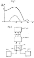
- FIG. 1 illustrates a typical aerial diagram for the known quadrifilar helix aerial (field strength FS as a function of the angle O from the antenna axis).
- the antenna has good coverage for right-hand polarised interference signal, almost up to 120° width in this case, but that a left-hand polarised interference signal also occurs at lobe angles around 90°, since this signal does not contribute further to the lobe width.
- the earth station is capable of receiveing (or transmitting) both ledt and right polarised signals at the same time, high cross polarisation could be useful. Most earth stations can receive both types.
- the antenna in the transmitter-receiver system it is included in is formed as an octofilar crossed helix antenna, resulting in that there is obtained the desired high cross polarisation, apart from the normal polarisation.
- LHC left polarised signals
- the proposed transmitter-receiver system is implemented as defined in the characterising portion of claim 1.
- Figure 1 is a lobe diagram for a known quadrifilar antenna.
- a first and a second transmitter-receiver unit are respectively denoted by SM1 and SM2 in the block diagram according to Figure 2. These units are conventional and are connected in a suitable way to a directional switch RK (3dB hybrid). Both outputs of the switch are connected to an adaptor unit BL, a so-called « balun » which diverts the signals sent from the switch to four outputs in this case, from which signals with different phase shifts 0°, 90°, 180° and 270° are obtained.
- the balun BL shown in detail in Figure 4, further serves as mechanical support for the antenna unit AN, which is shown in more detail in Figure 3.
- This unit is an octofilar crossed helix antenna, which has the property of transmitting and receiving cross-polarised signals, such that it acts omnidirectionally within a given angle O.
- the fact that the antenna unit ARI has high cross polarisation enables both right and left polarised signals to be processed by the system, providing that both types of signals can be processed simultaneously or individually by the earth station.
- the transmitter-receiver unit SMI may be intended for the right-hand polarised (RHC) signals as chief polarisation, while the unit SM2 is then intended for the left-hand polarised (LHC) signals as chief polarisation.
- the directional switch RK equally divides the power from a transmitter-receiver unit on its two outputs, mutually phase-shifted 90°.
- the radiation diagram for the antenna AN will have the appearance depicted in Figure 5.
- the radiation diagram from the unit SM2, which is then connected to the other input of the switch RK, will have the appearance as in Figure 5, except that the denotations RHC and LHC change places.
- Which SM unit is used depends on the application, but most usual is that SM2 replaces SM1 if the latter fails, i. e. a redundant system. It is, however, quite possible to use both transmitter-receiver units simultaneously.
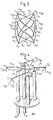
- Figure 3 illustrates the appearance of the antenna unit AN in more detail.
- this is an octofilar crossed helix antenna, in contradistinction to previously known systems, in which a quadrifilar helix was utilised.
- the antenna is in principle built up from two crossing arms with a given mutual spacing.
- One pair of crossed arms a,, a3 and a 2 , a4 define an upper antenna plane with end points k 1 -k 4 , and the other pair a 5 -a 7 and a 6 , as defines a lower antenna plane with end points k 5 -k 8 .
- the arms a 1 -a 4 in the upper plane and arms as-as in the lower are situated relative each other such that respective end points k 1 -k 4 and k 5 -k 8 are directly opposing, i. e. end point k, is opposite k s , k 2 is opposite k 6 etc.
- Two wires run from each point in the upper plane to the end points in the lower plane, that are situated nearest before and nearest after the end point, opposite the first-mentioned end point.
- the wires t l6 and t, 8 run from the end point k 1 to the end points k 6 and k 8 in the lower plane
- the wires e 25 and e 27 run correspondingly from the end point k 2 to the points k s and k 7
- the wires t 36 and t38 from the end point k 3 to end points k 6 and k 8
- the wires t 45 , t 47 run from the end point k 4 to the points k 5 and k 7 .
- the octofilar helix antenna illustrated in Figure may be said to consist of two quadrifilar helix antenna, of which one (antenna elements : wires t 18 , t 25 , t 36 , t 47 ) can receive left polarised, and the other (antenna elements : wire t 16 , t 27 , t 38 , t 45 ) can receive right polarised signals.
- the antenna radiation element thus comprises conductive wires (usually of copper), which depart in pairs from each of four end points k l , k 2 , k 3 , k 4 in a plane, the wires being bent and twisted with uniform pitch a quarter of a turn forwards or backwards, as respectively seen from each of the end points in the upper and lower planes of the antenna.
- conductive wires usually of copper
- FIG. 5 is the radiation diagram for the octofilar helix antenna according to Figure 3 with right-hand polarisation. It will be seen from the diagram that the antenna lobe angle for both left and right polarised signals is increased, particularly for left polarised signals (cross polarised), compared with the diagram of Figure 1.
- RHC right-hand polarised signals
- LHC left-hand polarised signals
- the location of the radiation lobes (field strength) in the 0 direction may be changed for a given microfrequency by changing the radial distance r and/or the height h, the pitch angle O in Figure 3.
- FIG 4 illustrates in detail how the octofilar helix antenna is arranged at its feed end (the upper antenna plane) as a balun.
- the four coaxial conductors b1-b4 of the balun have their respective screens connected to a common earth or ground plane JP.
- the centre conductors are connected to the four arms a1, a4, of the helix antenna, these being split up in pairs and each pair bridged by a bridge b13 and b24, respectively. Feeding the microwave signals to the four arms a1-a4 is thus obtained, the arms being mutually relatively displaced by 90°.
- the antenna elements i. e.
- the wires t8, t16 etc run from the respective end points k1-k4 of the arms a1-a4, as illustrated in Figure 3.
- the end points k5, k6, k7 and k8 may be attached by the' arms a5-a6 to the balun ground plane JP in a suitable way, or by an unillustrated screen to the balun, e. g. as illustrated for the quadrifilar helix antenna, discussed in the above-mentioned article from « The Microwave Journal , see Figure 1.
- the helix antenna radiation elements i. e. the wires t6, t18 etc, may each have a length equal to a multiple of ⁇ /2, so that they form a resonant antenna, which is the preferred embodiment. In some applications, however, it is advantageous to form the antenna as non-resonant.
- the antenna may be manufactured according to known technique. It is very light with wide bandwidth, compared with a slitted wave conductor antenna.
- the inventive system is primarily intended as a link antenna in satellite projects concerned with so-called relemetry and rele command links.
Landscapes
- Variable-Direction Aerials And Aerial Arrays (AREA)
- Radio Relay Systems (AREA)
Claims (2)
Applications Claiming Priority (2)
| Application Number | Priority Date | Filing Date | Title |
|---|---|---|---|
| SE8403812 | 1984-07-20 | ||
| SE8403812A SE443691B (sv) | 1984-07-20 | 1984-07-20 | Sendar-mottagarsystem i en satellit |
Publications (2)
| Publication Number | Publication Date |
|---|---|
| EP0169823A1 EP0169823A1 (fr) | 1986-01-29 |
| EP0169823B1 true EP0169823B1 (fr) | 1988-07-06 |
Family
ID=20356580
Family Applications (1)
| Application Number | Title | Priority Date | Filing Date |
|---|---|---|---|
| EP85850204A Expired EP0169823B1 (fr) | 1984-07-20 | 1985-06-12 | Système émetteur-récepteur d'un satellite |
Country Status (4)
| Country | Link |
|---|---|
| EP (1) | EP0169823B1 (fr) |
| DE (1) | DE3563673D1 (fr) |
| ES (1) | ES8704053A1 (fr) |
| SE (1) | SE443691B (fr) |
Families Citing this family (7)
| Publication number | Priority date | Publication date | Assignee | Title |
|---|---|---|---|---|
| FR2597267B1 (fr) * | 1986-04-15 | 1988-07-22 | Alcatel Espace | Antenne a haute efficacite |
| FR2654554B1 (fr) * | 1989-11-10 | 1992-07-31 | France Etat | Antenne en helice, quadrifilaire, resonnante bicouche. |
| AU693616B2 (en) * | 1994-12-06 | 1998-07-02 | Andrew Llc | A helical antenna |
| US6025816A (en) * | 1996-12-24 | 2000-02-15 | Ericsson Inc. | Antenna system for dual mode satellite/cellular portable phone |
| EP0957533B1 (fr) * | 1997-12-03 | 2004-05-06 | Mitsubishi Denki Kabushiki Kaisha | Dispositif antenne combine |
| JP3892129B2 (ja) * | 1998-01-23 | 2007-03-14 | 松下電器産業株式会社 | 携帯無線機 |
| GB0623774D0 (en) | 2006-11-28 | 2007-01-10 | Sarantel Ltd | An Antenna Assembly Including a Dielectrically Loaded Antenna |
Family Cites Families (2)
| Publication number | Priority date | Publication date | Assignee | Title |
|---|---|---|---|---|
| DE1129191B (de) * | 1960-12-14 | 1962-05-10 | Siemens Ag | Richtantenne fuer sehr kurze elektromagnetische Wellen |
| US4011567A (en) * | 1976-01-28 | 1977-03-08 | Rca Corporation | Circularly polarized, broadside firing, multihelical antenna |
-
1984
- 1984-07-20 SE SE8403812A patent/SE443691B/sv not_active IP Right Cessation
-
1985
- 1985-06-12 EP EP85850204A patent/EP0169823B1/fr not_active Expired
- 1985-06-12 DE DE8585850204T patent/DE3563673D1/de not_active Expired
- 1985-07-19 ES ES545381A patent/ES8704053A1/es not_active Expired
Non-Patent Citations (2)
| Title |
|---|
| K. ROTHAMMEL: "Antennenbruch", 7. Edition, 1981 Telekosmos Verlag, pages 468-472. * |
| THE MICROWAVE JOURNAL, December 1970, pages 49-54, C. KILGUS: "Resonant Quadrifilar Helix Design" * |
Also Published As
| Publication number | Publication date |
|---|---|
| DE3563673D1 (en) | 1988-08-11 |
| ES545381A0 (es) | 1987-03-01 |
| SE8403812D0 (sv) | 1984-07-20 |
| SE8403812L (sv) | 1986-01-21 |
| SE443691B (sv) | 1986-03-03 |
| ES8704053A1 (es) | 1987-03-01 |
| EP0169823A1 (fr) | 1986-01-29 |
Similar Documents
| Publication | Publication Date | Title |
|---|---|---|
| CA1057392A (fr) | Antenne a polarisation circulaire double frequence pour les communications par satelite, la navigation et autres usages connexes | |
| EP1301967B1 (fr) | Antenne à dipoles croisés regroupés | |
| EP2201644B1 (fr) | Antenne multifilaire à double polarisation | |
| US6154180A (en) | Multiband antennas | |
| US8537063B2 (en) | Antenna for reception of satellite radio signals emitted circularly, in a direction of rotation of the polarization | |
| EP0172626B1 (fr) | Dispositif d'antenne adaptive en direction | |
| US4349824A (en) | Around-a-mast quadrifilar microstrip antenna | |
| US5220340A (en) | Directional switched beam antenna | |
| US4427984A (en) | Phase-variable spiral antenna and steerable arrays thereof | |
| WO2003038946A1 (fr) | Antenne reseau a bande large en configuration etoilee | |
| JP2002026648A (ja) | 改善された電磁波を送受信するソースアンテナ | |
| US20040135732A1 (en) | Dual port helical-dipole antenna and array | |
| US6765541B1 (en) | Capacitatively shunted quadrifilar helix antenna | |
| EP1608038A1 (fr) | Antenne hélicoidale quadrifilaire | |
| CA1250046A (fr) | Antenne micro-ondes plates pour capter des ondes a polarisation circulaire | |
| US2953786A (en) | Antenna for polarized propagation | |
| US20040135736A1 (en) | Time-delayed directional beam phased array antenna | |
| US20080094307A1 (en) | Dual polarized multifilar antenna | |
| EP0169823B1 (fr) | Système émetteur-récepteur d'un satellite | |
| JP3169378B2 (ja) | アンテナ装置 | |
| US4983987A (en) | Antenna | |
| Abdel-Wahab et al. | Affordable large scale active-phased array antenna for Ka-band mobile SATCOM applications | |
| USH605H (en) | Multi-element adaptive antenna array | |
| EP0362165B1 (fr) | Procédé d'alimentation de puissance électromagnétique d'élément-antenne | |
| Maddocks et al. | Flat-plate steerable antennas for satellite communications and broadcast reception |
Legal Events
| Date | Code | Title | Description |
|---|---|---|---|
| PUAI | Public reference made under article 153(3) epc to a published international application that has entered the european phase |
Free format text: ORIGINAL CODE: 0009012 |
|
| AK | Designated contracting states |
Designated state(s): DE FR GB IT |
|
| 17P | Request for examination filed |
Effective date: 19860213 |
|
| 17Q | First examination report despatched |
Effective date: 19870529 |
|
| GRAA | (expected) grant |
Free format text: ORIGINAL CODE: 0009210 |
|
| AK | Designated contracting states |
Kind code of ref document: B1 Designated state(s): DE FR GB IT |
|
| ITF | It: translation for a ep patent filed | ||
| REF | Corresponds to: |
Ref document number: 3563673 Country of ref document: DE Date of ref document: 19880811 |
|
| ET | Fr: translation filed | ||
| PLBE | No opposition filed within time limit |
Free format text: ORIGINAL CODE: 0009261 |
|
| STAA | Information on the status of an ep patent application or granted ep patent |
Free format text: STATUS: NO OPPOSITION FILED WITHIN TIME LIMIT |
|
| 26N | No opposition filed | ||
| ITTA | It: last paid annual fee | ||
| PGFP | Annual fee paid to national office [announced via postgrant information from national office to epo] |
Ref country code: FR Payment date: 19990519 Year of fee payment: 15 |
|
| PGFP | Annual fee paid to national office [announced via postgrant information from national office to epo] |
Ref country code: GB Payment date: 19990520 Year of fee payment: 15 |
|
| PGFP | Annual fee paid to national office [announced via postgrant information from national office to epo] |
Ref country code: DE Payment date: 19990521 Year of fee payment: 15 |
|
| PG25 | Lapsed in a contracting state [announced via postgrant information from national office to epo] |
Ref country code: GB Free format text: LAPSE BECAUSE OF NON-PAYMENT OF DUE FEES Effective date: 20000612 |
|
| GBPC | Gb: european patent ceased through non-payment of renewal fee |
Effective date: 20000612 |
|
| PG25 | Lapsed in a contracting state [announced via postgrant information from national office to epo] |
Ref country code: FR Free format text: LAPSE BECAUSE OF NON-PAYMENT OF DUE FEES Effective date: 20010228 |
|
| REG | Reference to a national code |
Ref country code: FR Ref legal event code: ST |
|
| PG25 | Lapsed in a contracting state [announced via postgrant information from national office to epo] |
Ref country code: DE Free format text: LAPSE BECAUSE OF NON-PAYMENT OF DUE FEES Effective date: 20010403 |