EP0169956A1 - Trägergeschoss mit mehreren Innengeschossen - Google Patents
Trägergeschoss mit mehreren Innengeschossen Download PDFInfo
- Publication number
- EP0169956A1 EP0169956A1 EP84402635A EP84402635A EP0169956A1 EP 0169956 A1 EP0169956 A1 EP 0169956A1 EP 84402635 A EP84402635 A EP 84402635A EP 84402635 A EP84402635 A EP 84402635A EP 0169956 A1 EP0169956 A1 EP 0169956A1
- Authority
- EP
- European Patent Office
- Prior art keywords
- projectiles
- military charge
- gas
- military
- piston
- Prior art date
- Legal status (The legal status is an assumption and is not a legal conclusion. Google has not performed a legal analysis and makes no representation as to the accuracy of the status listed.)
- Granted
Links
Images


Classifications
-
- F—MECHANICAL ENGINEERING; LIGHTING; HEATING; WEAPONS; BLASTING
- F42—AMMUNITION; BLASTING
- F42B—EXPLOSIVE CHARGES, e.g. FOR BLASTING, FIREWORKS, AMMUNITION
- F42B3/00—Blasting cartridges, i.e. case and explosive
- F42B3/006—Explosive bolts; Explosive actuators
-
- F—MECHANICAL ENGINEERING; LIGHTING; HEATING; WEAPONS; BLASTING
- F42—AMMUNITION; BLASTING
- F42B—EXPLOSIVE CHARGES, e.g. FOR BLASTING, FIREWORKS, AMMUNITION
- F42B12/00—Projectiles, missiles or mines characterised by the warhead, the intended effect, or the material
- F42B12/02—Projectiles, missiles or mines characterised by the warhead, the intended effect, or the material characterised by the warhead or the intended effect
- F42B12/36—Projectiles, missiles or mines characterised by the warhead, the intended effect, or the material characterised by the warhead or the intended effect for dispensing materials; for producing chemical or physical reaction; for signalling ; for transmitting information
- F42B12/56—Projectiles, missiles or mines characterised by the warhead, the intended effect, or the material characterised by the warhead or the intended effect for dispensing materials; for producing chemical or physical reaction; for signalling ; for transmitting information for dispensing discrete solid bodies
- F42B12/58—Cluster or cargo ammunition, i.e. projectiles containing one or more submissiles
- F42B12/60—Cluster or cargo ammunition, i.e. projectiles containing one or more submissiles the submissiles being ejected radially
Definitions
- the present invention relates to the field of bombs, missiles and similar vectors, and it relates to a military charge with multiple heads intended for such vectors.
- the invention proposes to carry out a military charge with multiple heads whose destructive power is at least equal to that of a salvo of projectiles fired by an aircraft, and to mount this multi-headed military charge in a vector carried by an aircraft so that this aircraft remains outside the range of the enemy's defensive weapons.
- the object of the invention is a military charge with multiple heads intended to be carried by a bomb, a missile or a similar vector, in this charge groups of submunitions, such as projectiles, are arranged in crown to be radially extracted on the terminal trajectory of the carrier vector;
- this military charge includes a streamlined supporting structure having a retractable outer casing and a central tube which carries an annular support for each of the projectile groups; this annular support comprises arranged radially and facing the projectiles of the triggerable gas ejectors and means of clamping with bolts, which bolts are erased under the effect of the displacement of the gas ejectors.
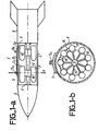
- the figure la in a simplified form, shows a missile intended to be carried and launched by an aircraft which remains outside the perimeter of defense of the enemy; this missile is equipped with a multi-head military charge.
- the missile 1 comprises three main sections: a front section 2 of ogival shape, in which are gathered the guide means allowing the missile to direct itself on the sensitive point of the designated objective; a middle section 3 constituted by the military charge with heads multiple and a tail fin section 4 which possibly contains the accelerator of the missile fired after its launch by the carrier aircraft.
- the military charge 3 essentially comprises a supporting structure, closed by an envelope, in which are arranged means making it possible to radially eject groups G and G 2 of projectiles P arranged in a ring.
- the structure carrying the military load comprises a central tube 3 secured to two connecting flanges 6 and 7 with the envelope.
- the connection of the flanges with the envelope is temporary, and the envelope includes means of fragmentation or sliding, with the aim of completely discovering the projectiles a short instant before their ejection from the military charge.
- the envelope 8 is equipped with a rigid beam 9 provided with attachment rings 9a and 9b to the aircraft, not shown.
- the central tube 3 of the supporting structure carries annular supports 10 and 10 'on which the projectiles are fixed.
- ejectors the function of which is to radially eject each of the projectiles P, which projectiles are clamped on their support by unlocking clamping means in synchronism with the movement of the ejectors.
- missile 1 When approaching the designated objective, missile 1 is dropped by the carrier aircraft, then guided towards the sensitive point. In the vicinity of this sensitive point the envelope 8 of the military charge is ousted, then, jointly, the means for clamping the projectiles P are unlocked and then, the ejectors are actuated to impart to the projectiles a determined lateral ejection speed, which conditions the dispersal of projectiles on the ground.
- the ejection speed is between a few meters and a few tens of meters per second. It may be noted that it is possible by dimensioning the ejectors to provide different ejection speeds for the different groups of projectiles.
- Figure 1b is a cross section along A of the military charge.
- the projectiles P resting on the annular support 10 are clamped by elastic flanges 14 provided with clamping means 15 deverroulllables at the instant of the extraction of the projectiles by the gas ejectors 13.
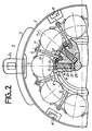
- FIG. 2 is a partial view, in cross section, of a form of construction of a multi-head military charge according to the invention, which shows the elements associated with the annular support 10.
- the outer casing 8 is equipped with 'a rigid powder 9 provided with attachment rings, such as the ring 9a.
- This envelope includes pyrotechnic means 11 intended to cause the fragmentation of the envelope before the ejection of the projectiles P.
- the number of fragmentation generators is not limited to three, as in the embodiment considered here, but can be bigger.
- Similar pyrotechnic means (not shown) make it possible to release the fragments of the envelope from the flanges of the support structure. Since the techniques for retracting the fairing elements of missiles and rockets are widely known, these will not be described.
- the annular support 8 at its periphery, comprises seats 12 on which rest, also spaced, the bodies of the projectiles.
- gas ejectors 13 are incorporated which are arranged radially and facing each of the projectiles.
- the projectiles are held rigidly on their seats by an elastic flange 14 whose ends come into pressure on the body of the adjacent projectiles Pi and Pi + 1.
- the middle part of these retaining flanges is provided with a clamping rod 15 which comprises a conical base 16, which is engaged in a housing 17 located in the annular support 10 and in the plane of the pneumatic ejectors 13.
- the head of the clamping rod 15 is provided with a thread which receives a clamping nut 18.
- the gas ejector 13 comprises a stepped bore 19 inside which is placed a piston 20.
- This piston comprises a pusher head 21 which is resting on the shoulder of the bore; this pusher head provides a means of locking the rod tightening 13 of the elastic flange 14.
- the base of the piston is equipped with a sealing means, such as an O-ring 22, which prevents the passage of gases supplied by a pellet 23 of a pyrotechnic substance which can be primed preferably electrically.
- the base of the bores 19 communicates with a gas source situated in the axis of the annular support.
- the base 16 of the clamping rod 15 and the pusher head 20 of the gas ejector communicate by a housing, inside which is placed the locking piece 24, which can freely slide and disappear from the housing 17 of the clamping rod during the translational movement of the piston, as soon as the pusher head 21 leaves the shoulder of the stepped bore 19. It may be noted that a shearable pin 25 under the effect of the displacement of the piston is disposed in the piston head to ensure that it remains on the shoulder of the bore.
- the ignition of the pyrotechnic pellet 23 produces a flow of gas which pushes the piston 20 outward. the ejector.
- the head of the piston 21 gradually disengages and releases the locking piece 24.
- This locking piece under the effect of the elastic stress of the flange 14, transmitted by the clamping rod 15 moves towards the body of the piston and releases totally the housing 17 of the base 16 of the clamping rod of its housing 17.
- the head of the piston 21 continues its movement and comes into contact with the body of the projectile on which it exerts a pressure force which ensures the ejection of the projectile .
- the speed of ejection of the projectile can be controlled.
- FIG. 3 shows a sectional view of a construction variant of the gas ejectors.
- the purpose of this construction variant is to prevent the piston head 21 from striking the body of the projectile, and it makes it possible to eliminate the shear pin 25 described above.
- Inside the piston is formed a bore 26 which receives a push rod 27.
- the upper end of the push rod is held in contact with the body by an elastic means 28 arranged between the lower end of this push rod and the bottom of the bore 26.
- This elastic means 28 can be constituted by a helical spring, a stack of washers "Belleville” or any other equivalent means.
- the function of the spring 28 is also to delay the pushing force on the projectile as long as the locking piece 24 of the clamping rod 15 is not retracted.
- the lower ends of the bores 19 of the gas ejectors are in communication with a central cavity 29 in which is disposed a gas generator which will be described later.
- FIG 4 is a partial view, in longitudinal section, of the military charge which shows the details of embodiment of the annular support of an odd grouping of P projectiles.
- the annular support 10 is a solid element which fits on the central tube 5 of the supporting structure.
- the two series of protuberances are sufficiently distant from each other to ensure proper seating of the projectiles.
- the protrusions 30 and 31 preferably provide point contacts with the body of the projectiles, and these contact points are advantageously located in diametrical planes which contain the elastic forces exerted by the flanges 14 described above.
- the central part of the annular support carries a bootable gas generator 29.
- the gas generator comprises a tube 32 in which is placed a pyrotechnic substance and an electrical primer 33 provided with its electrical terminals 34.
- a chamber 35 located concentrically with the tube 32 of the gas generator, has communication orifices 36 with the gas ejectors.
- the housing 17 of one of the clamping rods of the projectile holding flanges In order to position the projectiles longitudinally, they are provided a longitudinal positioning element such as the stud 37. This stud engages freely in a recess 38 so as not to disturb the ejection of the corresponding projectile.
- the stud 37 located in the body of the projectiles can be a retractable element intended to neutralize the arming of the projectiles.
- the point of application of the thrust force supplied by the thrust head 27 of the gas ejectors is located precisely with respect to the center of gravity CG of the projectiles.
- FIG. 3 represents an external view of the annular support 10 of the projectiles and it shows the following elements: the two series of protrusions 30 and 31 which provide foundations for the bodies of the projectiles; the outlets of the stepped bore of the gas ejectors, and the indentations 38 which receive the longitudinal positioning elements of the projectiles.
- FIG. 6 in a sectional view shows a variant construction of the gas ejector and means for locking the clamping rod of the electric flange for holding the projectiles on the annular support.
- the gas ejector 13 is of the telescopic type comprising an external hollow piston 20a placed in the stepped bore 19a, and an internal piston 27a.
- the external piston 20a has at its base a boss 20b whose function is to provide a first bearing on the wall of the stepped bore 19a; the second bearing is provided by a ring 20c bearing on a complementary shoulder 19b of the stepped bore; this ring 20c being held in place by a cerclip 19c.
- the base of the external piston 20a has a support piece 20d for a spring 28a which is also supported on the base of the internal piston 27a.
- the upper part of the external piston has a piston head 21a which ensures the locking piece 24a for locking the base 16a of the clamping rod 15 of the elastic flange 14.
- the base 16a of the clamping rod 15 is cylindrical shape to ensure its perfect guidance in the housing 17 and it includes a milling 16b in which can engage the locking piece 24a.
- the form of construction which has just been described makes it possible to impart a high lateral ejection speed. projectiles when necessary, and together, it provides improved guidance of the clamping rod of the elastic flange holding the projectiles.
- the construction form of the streamlined supporting structure can be varied, and, in particular, the means making it possible to retract the envelope can be of an extraction type along the longitudinal axis of the missile.
- the spacings of the projectiles are minimized to confer maximum carrying capacity on the load; the means for fixing and ejecting the projectiles operate in perfect synchronism and cooperate judiciously to ensure uniform and controlled dispersion of the projectiles, and the simplicity of the mechanisms confers certain reliability on the military charge.
- the invention is not limited in its applications to a military charge formed of projectiles, but it can be applied to the launches of explosive mines of various munitions etc ... which must be deposited on the ground.
Landscapes
- Engineering & Computer Science (AREA)
- General Engineering & Computer Science (AREA)
- Chemical & Material Sciences (AREA)
- Combustion & Propulsion (AREA)
- Jet Pumps And Other Pumps (AREA)
- Portable Nailing Machines And Staplers (AREA)
- Aiming, Guidance, Guns With A Light Source, Armor, Camouflage, And Targets (AREA)
Applications Claiming Priority (2)
| Application Number | Priority Date | Filing Date | Title |
|---|---|---|---|
| FR8320839 | 1983-12-27 | ||
| FR8320839A FR2557286B1 (fr) | 1983-12-27 | 1983-12-27 | Charge militaire a tetes multiples |
Publications (2)
| Publication Number | Publication Date |
|---|---|
| EP0169956A1 true EP0169956A1 (de) | 1986-02-05 |
| EP0169956B1 EP0169956B1 (de) | 1988-07-13 |
Family
ID=9295599
Family Applications (1)
| Application Number | Title | Priority Date | Filing Date |
|---|---|---|---|
| EP84402635A Expired EP0169956B1 (de) | 1983-12-27 | 1984-12-18 | Trägergeschoss mit mehreren Innengeschossen |
Country Status (4)
| Country | Link |
|---|---|
| US (1) | US4688486A (de) |
| EP (1) | EP0169956B1 (de) |
| DE (1) | DE3472719D1 (de) |
| FR (1) | FR2557286B1 (de) |
Cited By (3)
| Publication number | Priority date | Publication date | Assignee | Title |
|---|---|---|---|---|
| FR2641858A1 (fr) * | 1989-01-17 | 1990-07-20 | Thomson Brandt Armements | Dispositif de deverrouillage pneumatique pour munitions largables a partir d'un vecteur |
| DE4033476A1 (de) * | 1990-10-20 | 1992-04-23 | Messerschmitt Boelkow Blohm | Ausstossmodul fuer submunitionsbehaelter |
| US8607693B2 (en) | 2007-07-12 | 2013-12-17 | Jet Liquids Gmbh | Device and method for the preparation of a frothy liquid for human consumption |
Families Citing this family (25)
| Publication number | Priority date | Publication date | Assignee | Title |
|---|---|---|---|---|
| FR2594219B1 (fr) * | 1986-02-13 | 1989-12-15 | Rafaut & Cie | Dispositif d'ejection, en particulier pour munitions |
| US4845818A (en) * | 1986-07-16 | 1989-07-11 | Perry Oliver L | Device for changing fuel pump on internal combustion engine |
| DE3711992C1 (de) * | 1987-04-09 | 1999-03-11 | Daimler Benz Aerospace Ag | Streubehälter für Munition |
| FR2617464B1 (fr) * | 1987-07-03 | 1990-02-16 | Thomson Brandt Armements | Dispositif de fermeture ejectable, notamment pour roquettes a sous-munitions |
| US9476682B1 (en) * | 1989-01-26 | 2016-10-25 | Qinetiq Limited | Multi-charge munitions, incorporating hole-boring charge assemblies |
| US5107767A (en) * | 1989-06-26 | 1992-04-28 | Olin Corporation | Inflatable bladder submunition dispensing system |
| US5005481A (en) * | 1989-06-26 | 1991-04-09 | Olin Corporation | Inflatable bladder submunition dispensing system |
| US5231928A (en) * | 1990-08-24 | 1993-08-03 | Talley Defense Systems, Inc. | Munition release system |
| US5225627A (en) * | 1990-08-24 | 1993-07-06 | Talley Defense Systems, Incorporated | Tailored munition ejection system |
| US6138951A (en) * | 1998-08-10 | 2000-10-31 | Mcdonnell Douglas Corporation | Spacecraft dispensing system |
| SE522934C2 (sv) * | 2000-07-03 | 2004-03-16 | Bofors Defence Ab | Sätt och anordning för spridning av substridsdelar |
| US8082848B2 (en) | 2008-10-22 | 2011-12-27 | Raytheon Company | Missile with system for separating subvehicles |
| US8079416B2 (en) * | 2009-03-13 | 2011-12-20 | Reservoir Management Inc. | Plug for a perforated liner and method of using same |
| US8607705B2 (en) * | 2010-12-06 | 2013-12-17 | Systima Technologies Inc. | Low shock rocket body separation |
| US9273944B2 (en) | 2011-04-08 | 2016-03-01 | Innovative Defense, Llc | Segmented missile approach |
| US9175940B1 (en) | 2013-02-15 | 2015-11-03 | Innovation Defense, LLC | Revolved arc profile axisymmetric explosively formed projectile shaped charge |
| FR3035076B1 (fr) * | 2015-04-17 | 2018-04-20 | Thales | Procede d'amenagement d'une pluralite de vaisseaux spatiaux sous la coiffe d'un lanceur, assemblage resultant d'un tel procede et dispenser adapte a un tel assemblage |
| US9360222B1 (en) | 2015-05-28 | 2016-06-07 | Innovative Defense, Llc | Axilinear shaped charge |
| US10364387B2 (en) | 2016-07-29 | 2019-07-30 | Innovative Defense, Llc | Subterranean formation shock fracturing charge delivery system |
| US11254453B2 (en) | 2016-11-14 | 2022-02-22 | Space Systems/Loral, Llc | Smallsat payload configuration |
| CN109229409B (zh) * | 2018-10-23 | 2022-04-05 | 西北工业大学 | 一种集束式小型无人机空中快速发射系统 |
| US11609073B2 (en) | 2019-03-21 | 2023-03-21 | Corvid Technologies LLC | Munitions and methods for operating same |
| EP3854699B1 (de) * | 2020-01-21 | 2025-06-18 | Space Systems/Loral, LLC | Nutzlastkonfiguration eines kleinsatelliten |
| CN112224432A (zh) * | 2020-09-22 | 2021-01-15 | 南京航空航天大学 | 一种适用于混合编组飞行器批量空基发射的干扰弹 |
| CN119085419B (zh) * | 2024-08-30 | 2025-10-17 | 南京航空航天大学 | 一种向子弹抛撒机构补充子弹的机构 |
Citations (4)
| Publication number | Priority date | Publication date | Assignee | Title |
|---|---|---|---|---|
| US2972946A (en) * | 1950-07-07 | 1961-02-28 | Thomas C Poulter | Bomb cluster |
| US3295444A (en) * | 1956-08-02 | 1967-01-03 | Vincent J Cushing | Dispersal type cluster warhead |
| US3461801A (en) * | 1968-01-25 | 1969-08-19 | Us Navy | Multi-canister ejecting device |
| EP0114901A1 (de) * | 1983-01-24 | 1984-08-08 | The Boeing Company | Vorrichtung für Geschosszerstreuung |
Family Cites Families (2)
| Publication number | Priority date | Publication date | Assignee | Title |
|---|---|---|---|---|
| DE2739299C2 (de) * | 1977-09-01 | 1984-01-19 | Messerschmitt-Bölkow-Blohm GmbH, 8000 München | Halterung für Streuwaffengroßbehälter |
| US4455943A (en) * | 1981-08-21 | 1984-06-26 | The Boeing Company | Missile deployment apparatus |
-
1983
- 1983-12-27 FR FR8320839A patent/FR2557286B1/fr not_active Expired
-
1984
- 1984-12-18 EP EP84402635A patent/EP0169956B1/de not_active Expired
- 1984-12-18 DE DE8484402635T patent/DE3472719D1/de not_active Expired
- 1984-12-24 US US06/685,780 patent/US4688486A/en not_active Expired - Fee Related
Patent Citations (4)
| Publication number | Priority date | Publication date | Assignee | Title |
|---|---|---|---|---|
| US2972946A (en) * | 1950-07-07 | 1961-02-28 | Thomas C Poulter | Bomb cluster |
| US3295444A (en) * | 1956-08-02 | 1967-01-03 | Vincent J Cushing | Dispersal type cluster warhead |
| US3461801A (en) * | 1968-01-25 | 1969-08-19 | Us Navy | Multi-canister ejecting device |
| EP0114901A1 (de) * | 1983-01-24 | 1984-08-08 | The Boeing Company | Vorrichtung für Geschosszerstreuung |
Cited By (5)
| Publication number | Priority date | Publication date | Assignee | Title |
|---|---|---|---|---|
| FR2641858A1 (fr) * | 1989-01-17 | 1990-07-20 | Thomson Brandt Armements | Dispositif de deverrouillage pneumatique pour munitions largables a partir d'un vecteur |
| EP0379402A1 (de) * | 1989-01-17 | 1990-07-25 | Thomson-Brandt Armements | Pneumatische Entriegelungsvorrichtung für aus einem Trägergeschoss ausklinkbare Munition |
| US4998480A (en) * | 1989-01-17 | 1991-03-12 | Thomson-Brandt Armements | Pneumatic unlocking device for munitions releasable from a carrier |
| DE4033476A1 (de) * | 1990-10-20 | 1992-04-23 | Messerschmitt Boelkow Blohm | Ausstossmodul fuer submunitionsbehaelter |
| US8607693B2 (en) | 2007-07-12 | 2013-12-17 | Jet Liquids Gmbh | Device and method for the preparation of a frothy liquid for human consumption |
Also Published As
| Publication number | Publication date |
|---|---|
| FR2557286B1 (fr) | 1986-12-05 |
| FR2557286A1 (fr) | 1985-06-28 |
| US4688486A (en) | 1987-08-25 |
| EP0169956B1 (de) | 1988-07-13 |
| DE3472719D1 (en) | 1988-08-18 |
Similar Documents
| Publication | Publication Date | Title |
|---|---|---|
| EP0169956B1 (de) | Trägergeschoss mit mehreren Innengeschossen | |
| US3461801A (en) | Multi-canister ejecting device | |
| EP3102906B1 (de) | Hohlladung und verwendung zur trennung von zwei stockwerken eines luftfahrtfahrzeugs oder zur neutralisierung davon | |
| US3086467A (en) | Gas operated extendible probe for ballistic model | |
| FR2572512A1 (fr) | Dispositif, adaptable sur engins ou munitions, tels que projectiles d'artillerie, destine a reduire leur trainee de culot | |
| WO2014080136A1 (fr) | Projectile gyrostabilise projetant une charge utile | |
| EP0086711B1 (de) | Treibkäfig für unterkalibriges Geschoss | |
| EP0130893B1 (de) | Trägergeschoss für Streumunition | |
| RU2227893C1 (ru) | Кассетная боевая часть | |
| FR2736714A1 (fr) | Tete de combat a double charge creuse | |
| EP0457657A1 (de) | Durchdringendes Geschoss | |
| FR2519752A1 (fr) | Perfectionnements apportes aux armes sol-sol a tir tendu agissant en survol de l'objectif | |
| EP1521053B1 (de) | Anti-Bunker Munition | |
| EP2546143B1 (de) | Geschützabschusssystem, insbesondere als Gegenmaßnahme von einem Luftfahrzeug aus | |
| FR2632397A2 (fr) | Cartouche pour la dispersion de leurres electromagnetiques | |
| EP2913628B1 (de) | Geschosszünder eines Artillerieprojektils, der eine in Flugrichtung wirkende Bremsvorrichtung umfasst | |
| FR2771495A1 (fr) | Tete militaire pour combattre des engins blindes munis de blindages reactifs | |
| KR101500640B1 (ko) | 자동분리 밀폐링이 장착된 포탄 | |
| RU2111372C1 (ru) | Ракетный двигатель твердого топлива | |
| EP0664433B1 (de) | Panzerabwehrgeschoss und eine mit einem solchen Geschoss versehene Munition | |
| US3215041A (en) | Strain locked nozzle for recoilless weapons | |
| FR2534681A1 (fr) | Perfectionnements apportes aux systemes d'armes lanceurs de projectiles, notamment aux charges propulsives et a la balistique interieure | |
| FR2590664A1 (fr) | Tete militaire | |
| FR2688304A1 (fr) | Corps de bombe perfectionne, procede de fabrication de tels corps de bombe, et bombes de divers types equipees d'un tel corps. | |
| BE571129A (de) |
Legal Events
| Date | Code | Title | Description |
|---|---|---|---|
| PUAI | Public reference made under article 153(3) epc to a published international application that has entered the european phase |
Free format text: ORIGINAL CODE: 0009012 |
|
| AK | Designated contracting states |
Designated state(s): AT BE CH DE GB IT LI LU NL SE |
|
| 17P | Request for examination filed |
Effective date: 19860614 |
|
| 17Q | First examination report despatched |
Effective date: 19870305 |
|
| GRAA | (expected) grant |
Free format text: ORIGINAL CODE: 0009210 |
|
| AK | Designated contracting states |
Kind code of ref document: B1 Designated state(s): DE GB IT SE |
|
| REF | Corresponds to: |
Ref document number: 3472719 Country of ref document: DE Date of ref document: 19880818 |
|
| GBT | Gb: translation of ep patent filed (gb section 77(6)(a)/1977) | ||
| ITF | It: translation for a ep patent filed | ||
| PLBE | No opposition filed within time limit |
Free format text: ORIGINAL CODE: 0009261 |
|
| STAA | Information on the status of an ep patent application or granted ep patent |
Free format text: STATUS: NO OPPOSITION FILED WITHIN TIME LIMIT |
|
| 26N | No opposition filed | ||
| PGFP | Annual fee paid to national office [announced via postgrant information from national office to epo] |
Ref country code: SE Payment date: 19911121 Year of fee payment: 8 |
|
| PGFP | Annual fee paid to national office [announced via postgrant information from national office to epo] |
Ref country code: GB Payment date: 19911122 Year of fee payment: 8 Ref country code: DE Payment date: 19911122 Year of fee payment: 8 |
|
| ITTA | It: last paid annual fee | ||
| PG25 | Lapsed in a contracting state [announced via postgrant information from national office to epo] |
Ref country code: GB Effective date: 19921218 |
|
| PG25 | Lapsed in a contracting state [announced via postgrant information from national office to epo] |
Ref country code: SE Effective date: 19921219 |
|
| GBPC | Gb: european patent ceased through non-payment of renewal fee |
Effective date: 19921218 |
|
| PG25 | Lapsed in a contracting state [announced via postgrant information from national office to epo] |
Ref country code: DE Effective date: 19930901 |
|
| EUG | Se: european patent has lapsed |
Ref document number: 84402635.1 Effective date: 19930709 |