EP0170064B1 - Système d'allumage électronique à distributeur statique pour moteur à carburateur - Google Patents
Système d'allumage électronique à distributeur statique pour moteur à carburateur Download PDFInfo
- Publication number
- EP0170064B1 EP0170064B1 EP85108003A EP85108003A EP0170064B1 EP 0170064 B1 EP0170064 B1 EP 0170064B1 EP 85108003 A EP85108003 A EP 85108003A EP 85108003 A EP85108003 A EP 85108003A EP 0170064 B1 EP0170064 B1 EP 0170064B1
- Authority
- EP
- European Patent Office
- Prior art keywords
- ignition
- current
- engine
- controlling
- transformers
- Prior art date
- Legal status (The legal status is an assumption and is not a legal conclusion. Google has not performed a legal analysis and makes no representation as to the accuracy of the status listed.)
- Expired
Links
Images
Classifications
-
- F—MECHANICAL ENGINEERING; LIGHTING; HEATING; WEAPONS; BLASTING
- F02—COMBUSTION ENGINES; HOT-GAS OR COMBUSTION-PRODUCT ENGINE PLANTS
- F02P—IGNITION, OTHER THAN COMPRESSION IGNITION, FOR INTERNAL-COMBUSTION ENGINES; TESTING OF IGNITION TIMING IN COMPRESSION-IGNITION ENGINES
- F02P7/00—Arrangements of distributors, circuit-makers or -breakers, e.g. of distributor and circuit-breaker combinations or pick-up devices
- F02P7/02—Arrangements of distributors, circuit-makers or -breakers, e.g. of distributor and circuit-breaker combinations or pick-up devices of distributors
- F02P7/03—Arrangements of distributors, circuit-makers or -breakers, e.g. of distributor and circuit-breaker combinations or pick-up devices of distributors with electrical means
- F02P7/035—Arrangements of distributors, circuit-makers or -breakers, e.g. of distributor and circuit-breaker combinations or pick-up devices of distributors with electrical means without mechanical switching means
-
- F—MECHANICAL ENGINEERING; LIGHTING; HEATING; WEAPONS; BLASTING
- F02—COMBUSTION ENGINES; HOT-GAS OR COMBUSTION-PRODUCT ENGINE PLANTS
- F02P—IGNITION, OTHER THAN COMPRESSION IGNITION, FOR INTERNAL-COMBUSTION ENGINES; TESTING OF IGNITION TIMING IN COMPRESSION-IGNITION ENGINES
- F02P3/00—Other installations
- F02P3/02—Other installations having inductive energy storage, e.g. arrangements of induction coils
- F02P3/04—Layout of circuits
- F02P3/045—Layout of circuits for control of the dwell or anti dwell time
- F02P3/0453—Opening or closing the primary coil circuit with semiconductor devices
- F02P3/0456—Opening or closing the primary coil circuit with semiconductor devices using digital techniques
-
- F—MECHANICAL ENGINEERING; LIGHTING; HEATING; WEAPONS; BLASTING
- F02—COMBUSTION ENGINES; HOT-GAS OR COMBUSTION-PRODUCT ENGINE PLANTS
- F02B—INTERNAL-COMBUSTION PISTON ENGINES; COMBUSTION ENGINES IN GENERAL
- F02B75/00—Other engines
- F02B75/02—Engines characterised by their cycles, e.g. six-stroke
- F02B2075/022—Engines characterised by their cycles, e.g. six-stroke having less than six strokes per cycle
- F02B2075/027—Engines characterised by their cycles, e.g. six-stroke having less than six strokes per cycle four
Definitions
- the present invention relates to an electronic ignition system with static distribution for a carburettor engine.
- the invention concerns an electronic ignition system for a four-stroke, four-cylinder engine, comprising:
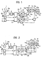
- FIG. 1 An electronic ignition system with static distribution of the known type described above is schematically illustrated in Figure 1 of the appended drawings.
- a phonic wheel-type sensor comprising a rotatable member 2 equipped with at least one detectable reference 3 and with two fixed pick-up elements 4a and 4b arranged at 180° to each other.
- the output of each pick-up element is connected to the input of a micro-processor unit 5 by means of a pulse-shaping and -forming circuit 6 (for example, a "trigger" circuit).
- the micro-processor unit 5 also has inputs connected to further sensors, for example, an engine temperature sensor 7 and a sensor 8 responsive to the degree of vacuum in the induction manifold of the engine.
- the electronic microprocessor unit 5 is predisposed by means of conventional programming techniques, to carry out electronic monitoring of the ignition advance, and to control the ignition in the cylinders of the engine by means of two identical control circuit modules 9 and 10, which will be described hereinafter. These circuit modules are respectively connected to a first and to a second controlled switching device 11, 12 (for example, 'Darlington' transistors) which in turn are connected to the input or primary windings 14a, 15a of two ignition transformers or 'coils' 14 and 15.
- a second controlled switching device 11, 12 for example, 'Darlington' transistors
- the ingition transformer 14 has its output or secondary winding 14b connected to the spark plugs C1 and C4 associated with a pair of cylinders of the engine, whilst the output or secondary winding 15b of the ignition transformer 15 is connected to the spark plugs C2 and C3 associated with the other two cylinders.
- Two feedback circuits 16 and 18 are respectively connected between the controlled switching devices 11 and 12 and the respective control circuit modules 9 and 10.
- Said modules each of which may, for example, comprise a dedicated integrated circuit L 482, manufactured and marketed by the Company SGS-ATES, comprise each a circuit 20 for controlling current flowing in the associated primary winding of the ignition transformers 14 or 15.
- This control circuit is of a conventional type, and is also known as a circuit for controlling the angle of "dwell".
- Each control circuit 20 is followed by a power stage 21 or "driver" stage equipped, for example, with transistors.
- each circuit module 9 or 10 determines the alternate switching of the switch devices 11 and 12, thus energising alternately and selectively the primary windings 14a and 15a of the ignition transformers 14 and 15.
- ignition is effected alternately, through the secondary windings 14b and 15b in the two pairs of cylinders of the engine, in dependence particularly on the signal provided by the sensor 1.
- each feedback circuit 16 or 18 furnishes to the respective circuit module 9 or 10 a signal indicative of the magnitude of the current flowing in the primary winding 14a or 15a.
- each circuit module-9 or 10 determines, according to pre-established methods, the magnitude and the duration of the current flow in the primary winding of the related ignition transformer at the subsequent ignition.
- JP-A-59 110 861 (which corresponds to EP-A-0 113 894) discloses an ignition circuit arrangement including a single ignition timing circuit which is coupled to either one or the other of two ignition transformers through a bistable switch device.
- This prior ignition circuit does not include any feedback control circuit for sensing and regulating the current flowing through the ignition transformers, so that the said current may be heavily affected by variations of the charge level of the d.c. voltage supply battery.
- the object of the present invention is to provide an ignition system of the type previously defined, which has a drastically simplified circuit structure compared with the known type of circuit previously described with reference to Figure 1 and which is thus capable of being produced more economically whilst, at the same time, ensuring performances comparable with that of the previous system.
- said integrated circuit means for controlling the angle of dwell comprise a single integrated circuit for controlling the angle of dwell, of the type capable of controlling the ignition transformer of one pair of cylinders;
- the switching circuit means comprise a first and a second electronically controlled switching device, respectively in series with the input winding of the first and of the second ignition transformer connected together so as to form two current paths which are connected in parallel with each other; and a third electronically controlled switching device connected to said micro- processor unit and capable of connecting alternately and selectively the control output of said integrated circuit for controlling the angle of "dwell" to said first or to said second controlled switching device in dependence on the signals emitted by said microprocessor unit;
- said current monitoring means comprising a single feedback circuit permanently connected to the said two parallel connected current paths and to said integrated circuit for controlling the angle of "dwell", whereby at each ignition the current flowing in the primary winding of one of said ignition transformers is adjusted in dependence on the current that has flowed in the primary winding of the other ignition transformer during the preceding ignition.
- the ignition system shown in Figure 2 includes a single integrated circuit 19 for controlling the angle of "dwell” and of ignition, this also consisting, for example, of an integrated circuit L482 of the SGS-ATES Company.
- the output of the integrated circuit 19 is connected to a switching device 30 controlled by the microprocessor unit 5.
- the switching circuit 30, which may be tran- sistorised, has two outputs connected to the control inputs of the controlled switching devices 11 and 12. The latter are connected together (in the case of 'Darlington' transistors, these have their emitters connected together) and their common terminal is connected to the integrated circuit 19 by means of a single feedback circuit 28, for example, a current divider, structurally identical to the feedback circuits 16 and 18 of Figure 1. '
- the microprocessor unit 5 through the switching circuit 30 and the integrated circuit 19, connects in the circuit the primary windings 14a and 15a of the two ignition transformers selectively and alternately. Since, when one of these windings conducts the other carries no current, and vice versa, a single feedback circuit is sufficient to "inform" the integrated circuit 19 of the magnitude of the current flowing in these windings.
- the current circulating in the primary winding of the corresponding ignition transformer is controlled by the integrated circuit 19 in dependence on the magnitude of the current measured, during the course of the immediately preceding ignition, by means of the feedback circuit 28.
- the current made to flow in the primary winding 14a to effect ignition is regulated in dependence on the current that flowed in the winding 15a during the immediately preceding ignition, and so on. It is therefore evident that, in order to obtain correct operation of the ignition system according to the invention, the windings 14a and 15a should as far as possible be identical. Such a condition may, however, be easily fulfilled.
- microprocessor unit 5 of the system illustrated in Figure 2 is, in terms of its circuit, identical to that of the system shown in Figure 1: there may be some minor differences in the operating programmes of this unit, but such differences would be fairly insignificant and would be instantly recognised by someone skilled in the art.
Landscapes
- Engineering & Computer Science (AREA)
- Chemical & Material Sciences (AREA)
- Combustion & Propulsion (AREA)
- Mechanical Engineering (AREA)
- General Engineering & Computer Science (AREA)
- Ignition Installations For Internal Combustion Engines (AREA)
Claims (4)
Priority Applications (1)
| Application Number | Priority Date | Filing Date | Title |
|---|---|---|---|
| AT85108003T ATE41977T1 (de) | 1984-06-29 | 1985-06-27 | Elektronisches zuendsystem mit statischem verteiler fuer einen vergasermotor. |
Applications Claiming Priority (2)
| Application Number | Priority Date | Filing Date | Title |
|---|---|---|---|
| IT6766884 | 1984-06-29 | ||
| IT8467668A IT1208333B (it) | 1984-06-29 | 1984-06-29 | Sistema di accensione elettronica a distribuzione statica per un motore a carburazione |
Publications (2)
| Publication Number | Publication Date |
|---|---|
| EP0170064A1 EP0170064A1 (fr) | 1986-02-05 |
| EP0170064B1 true EP0170064B1 (fr) | 1989-04-05 |
Family
ID=11304356
Family Applications (1)
| Application Number | Title | Priority Date | Filing Date |
|---|---|---|---|
| EP85108003A Expired EP0170064B1 (fr) | 1984-06-29 | 1985-06-27 | Système d'allumage électronique à distributeur statique pour moteur à carburateur |
Country Status (7)
| Country | Link |
|---|---|
| US (1) | US4660534A (fr) |
| EP (1) | EP0170064B1 (fr) |
| AT (1) | ATE41977T1 (fr) |
| DE (1) | DE3569273D1 (fr) |
| ES (1) | ES8607483A1 (fr) |
| IT (1) | IT1208333B (fr) |
| YU (1) | YU44723B (fr) |
Families Citing this family (8)
| Publication number | Priority date | Publication date | Assignee | Title |
|---|---|---|---|---|
| JPH0676791B2 (ja) * | 1986-03-03 | 1994-09-28 | 日本電装株式会社 | 内燃機関用点火装置 |
| JPS6371573A (ja) * | 1986-09-11 | 1988-03-31 | ゼネラル モーターズ コーポレーション | 内燃機関の点火装置及び該点火装置を作動させる方法 |
| US4750467A (en) * | 1986-09-11 | 1988-06-14 | General Motors Corporation | Internal combustion engine ignition system |
| JP2541949B2 (ja) * | 1986-11-28 | 1996-10-09 | 本田技研工業株式会社 | 4サイクル内燃機関の点火時期制御装置 |
| DE3841862A1 (de) * | 1988-12-13 | 1990-06-21 | Bosch Gmbh Robert | Verfahren zur steuerung einer brennkraftmaschine |
| US5027785A (en) * | 1990-04-19 | 1991-07-02 | Motorola, Inc. | Simplified ignition system for multi-cylinder engines |
| US5060623A (en) * | 1990-12-20 | 1991-10-29 | Caterpillar Inc. | Spark duration control for a capacitor discharge ignition system |
| GB9515272D0 (en) * | 1994-12-23 | 1995-09-20 | Philips Electronics Uk Ltd | An ignition control circuit, and engine system |
Family Cites Families (12)
| Publication number | Priority date | Publication date | Assignee | Title |
|---|---|---|---|---|
| US3267329A (en) * | 1963-04-03 | 1966-08-16 | Bendix Corp | Electrical ignition apparatus using a high voltage breakdown and a condenser followup through the ignition gap |
| US4112895A (en) * | 1973-05-10 | 1978-09-12 | Ducellier Et Cie | Electronic distribution and control device for the ignition of internal combustion engines, particularly for motor vehicles |
| US3940658A (en) * | 1973-12-26 | 1976-02-24 | Superior Industries, Inc. | Electronic ignition control system |
| DE2723801C2 (de) * | 1977-05-26 | 1992-04-02 | Robert Bosch Gmbh, 7000 Stuttgart | Zündanlage für Brennkraftmaschinen |
| FR2393948A1 (fr) * | 1977-06-10 | 1979-01-05 | Sev Marchal | Dispositif pour la distribution de la tension d'allumage d'un moteur a combustion interne |
| JPS54158536A (en) * | 1978-06-02 | 1979-12-14 | Hitachi Ltd | Current control circuit for ignition device |
| JPS5838627B2 (ja) * | 1978-06-23 | 1983-08-24 | 株式会社デンソー | 内燃機関用無接点点火装置 |
| US4265211A (en) * | 1979-11-23 | 1981-05-05 | General Motors Corporation | Distributorless internal combustion engine ignition system |
| US4378004A (en) * | 1981-02-23 | 1983-03-29 | Motorola Inc. | Engine control system with cylinder identification apparatus |
| US4483293A (en) * | 1982-04-06 | 1984-11-20 | Mitsubishi Denki Kabushiki Kaisha | Ignition time control device |
| FR2531749B1 (fr) * | 1982-08-11 | 1987-03-20 | Renault | Dispositif de commande de l'allumage et de l'injection de combustible pour un moteur a combustion interne |
| JPS59110861A (ja) * | 1982-12-16 | 1984-06-26 | Mitsubishi Electric Corp | 内燃機関点火装置 |
-
1984
- 1984-06-29 IT IT8467668A patent/IT1208333B/it active
-
1985
- 1985-06-27 AT AT85108003T patent/ATE41977T1/de active
- 1985-06-27 DE DE8585108003T patent/DE3569273D1/de not_active Expired
- 1985-06-27 EP EP85108003A patent/EP0170064B1/fr not_active Expired
- 1985-06-28 ES ES545017A patent/ES8607483A1/es not_active Expired
- 1985-06-28 US US06/749,891 patent/US4660534A/en not_active Expired - Fee Related
- 1985-07-01 YU YU1101/85A patent/YU44723B/xx unknown
Also Published As
| Publication number | Publication date |
|---|---|
| YU44723B (en) | 1990-12-31 |
| US4660534A (en) | 1987-04-28 |
| YU110185A (en) | 1988-08-31 |
| EP0170064A1 (fr) | 1986-02-05 |
| ATE41977T1 (de) | 1989-04-15 |
| DE3569273D1 (en) | 1989-05-11 |
| ES8607483A1 (es) | 1986-06-01 |
| IT1208333B (it) | 1989-06-12 |
| ES545017A0 (es) | 1986-06-01 |
| IT8467668A0 (it) | 1984-06-29 |
Similar Documents
| Publication | Publication Date | Title |
|---|---|---|
| US4176645A (en) | Motor ignition system control circuit for maintaining energy storage in spark coil constant in wide speed range | |
| US4740952A (en) | Device for the simultaneous transmission of two data signals over the same electrical line in opposite directions | |
| EP0170064B1 (fr) | Système d'allumage électronique à distributeur statique pour moteur à carburateur | |
| US5307786A (en) | Ignition apparatus for an internal combustion engine | |
| US4188926A (en) | Automotive internal combustion engine servo control system, particularly for automatic speed control arrangement | |
| US6044823A (en) | Fuel injector control system for cylinder injection type internal combustion engine | |
| US4217872A (en) | Multiple spark ignition system for an internal combustion engine | |
| US5220903A (en) | Electronic ignition system | |
| US6450157B1 (en) | Automotive ignition system with adaptable start-of-dwell ring damping | |
| US4949697A (en) | Igniter for an internal combustion engine | |
| GB1533225A (en) | Ignition system | |
| DE4215153C2 (de) | Zündvorrichtung für eine Mehrzylinderbrennkraftmaschine | |
| US4636620A (en) | Temperature compensation injector control system | |
| EP0040688B1 (fr) | Installation d'allumage sans contact pour moteurs à combustion interne avec compensation de la tension d'alimentation | |
| CA1132652A (fr) | Systeme d'avance a l'allumage tributaire du regime d'un moteur a combustion interne | |
| US4339781A (en) | Apparatus for controlling the electric current through an inductive consumer, in particular through a fuel metering valve in an internal combustion engine | |
| KR970701312A (ko) | 점화 제어 회로 및 엔진 시스템(An ignition control circuit. and engine system) | |
| US5033445A (en) | Electronic distribution type ignition system | |
| US4382431A (en) | Circuit for decreasing oscillatoins in the primary winding of an ignition coil of an internal combustion engine | |
| US4709684A (en) | Method of stabilizing current flow through an automotive-type ignition coil | |
| US5373826A (en) | Ignition apparatus for an internal combustion engine having a current limiting function | |
| GB1499631A (en) | Ignition systems | |
| JPS56101072A (en) | Ignition time controlling device of engine in which different kind of fuel being changed over and used | |
| US5113815A (en) | Ignition control apparatus for an internal combustion engine | |
| GB2177823A (en) | Current control circuit for a stepping motor |
Legal Events
| Date | Code | Title | Description |
|---|---|---|---|
| PUAI | Public reference made under article 153(3) epc to a published international application that has entered the european phase |
Free format text: ORIGINAL CODE: 0009012 |
|
| AK | Designated contracting states |
Designated state(s): AT BE CH DE FR GB IT LI LU NL SE |
|
| 17P | Request for examination filed |
Effective date: 19860123 |
|
| 17Q | First examination report despatched |
Effective date: 19880517 |
|
| RAP1 | Party data changed (applicant data changed or rights of an application transferred) |
Owner name: MARELLI AUTRONICA S.P.A. |
|
| GRAA | (expected) grant |
Free format text: ORIGINAL CODE: 0009210 |
|
| AK | Designated contracting states |
Kind code of ref document: B1 Designated state(s): AT BE CH DE FR GB IT LI LU NL SE |
|
| REF | Corresponds to: |
Ref document number: 41977 Country of ref document: AT Date of ref document: 19890415 Kind code of ref document: T |
|
| ITF | It: translation for a ep patent filed | ||
| REF | Corresponds to: |
Ref document number: 3569273 Country of ref document: DE Date of ref document: 19890511 |
|
| ET | Fr: translation filed | ||
| PLBE | No opposition filed within time limit |
Free format text: ORIGINAL CODE: 0009261 |
|
| STAA | Information on the status of an ep patent application or granted ep patent |
Free format text: STATUS: NO OPPOSITION FILED WITHIN TIME LIMIT |
|
| 26N | No opposition filed | ||
| PGFP | Annual fee paid to national office [announced via postgrant information from national office to epo] |
Ref country code: AT Payment date: 19920515 Year of fee payment: 8 |
|
| PGFP | Annual fee paid to national office [announced via postgrant information from national office to epo] |
Ref country code: BE Payment date: 19920520 Year of fee payment: 8 |
|
| PGFP | Annual fee paid to national office [announced via postgrant information from national office to epo] |
Ref country code: CH Payment date: 19920521 Year of fee payment: 8 |
|
| PGFP | Annual fee paid to national office [announced via postgrant information from national office to epo] |
Ref country code: LU Payment date: 19920603 Year of fee payment: 8 |
|
| PGFP | Annual fee paid to national office [announced via postgrant information from national office to epo] |
Ref country code: NL Payment date: 19920630 Year of fee payment: 8 |
|
| EPTA | Lu: last paid annual fee | ||
| PG25 | Lapsed in a contracting state [announced via postgrant information from national office to epo] |
Ref country code: LU Free format text: LAPSE BECAUSE OF NON-PAYMENT OF DUE FEES Effective date: 19930627 Ref country code: AT Effective date: 19930627 |
|
| PG25 | Lapsed in a contracting state [announced via postgrant information from national office to epo] |
Ref country code: LI Effective date: 19930630 Ref country code: CH Effective date: 19930630 Ref country code: BE Effective date: 19930630 |
|
| BERE | Be: lapsed |
Owner name: MARELLI AUTRONICA S.P.A. Effective date: 19930630 |
|
| PG25 | Lapsed in a contracting state [announced via postgrant information from national office to epo] |
Ref country code: NL Effective date: 19940101 |
|
| NLV4 | Nl: lapsed or anulled due to non-payment of the annual fee | ||
| REG | Reference to a national code |
Ref country code: CH Ref legal event code: PL |
|
| EAL | Se: european patent in force in sweden |
Ref document number: 85108003.6 |
|
| PGFP | Annual fee paid to national office [announced via postgrant information from national office to epo] |
Ref country code: SE Payment date: 19970506 Year of fee payment: 13 |
|
| PGFP | Annual fee paid to national office [announced via postgrant information from national office to epo] |
Ref country code: GB Payment date: 19970520 Year of fee payment: 13 |
|
| PGFP | Annual fee paid to national office [announced via postgrant information from national office to epo] |
Ref country code: DE Payment date: 19970523 Year of fee payment: 13 |
|
| PGFP | Annual fee paid to national office [announced via postgrant information from national office to epo] |
Ref country code: FR Payment date: 19970630 Year of fee payment: 13 |
|
| PG25 | Lapsed in a contracting state [announced via postgrant information from national office to epo] |
Ref country code: GB Free format text: LAPSE BECAUSE OF NON-PAYMENT OF DUE FEES Effective date: 19980627 |
|
| PG25 | Lapsed in a contracting state [announced via postgrant information from national office to epo] |
Ref country code: SE Free format text: LAPSE BECAUSE OF NON-PAYMENT OF DUE FEES Effective date: 19980628 |
|
| GBPC | Gb: european patent ceased through non-payment of renewal fee |
Effective date: 19980627 |
|
| PG25 | Lapsed in a contracting state [announced via postgrant information from national office to epo] |
Ref country code: FR Free format text: LAPSE BECAUSE OF NON-PAYMENT OF DUE FEES Effective date: 19990226 |
|
| EUG | Se: european patent has lapsed |
Ref document number: 85108003.6 |
|
| PG25 | Lapsed in a contracting state [announced via postgrant information from national office to epo] |
Ref country code: DE Free format text: LAPSE BECAUSE OF NON-PAYMENT OF DUE FEES Effective date: 19990401 |
|
| REG | Reference to a national code |
Ref country code: FR Ref legal event code: ST |