EP0170124A2 - Méthode et dispositif pour le démontage d'un pneumatique - Google Patents
Méthode et dispositif pour le démontage d'un pneumatique Download PDFInfo
- Publication number
- EP0170124A2 EP0170124A2 EP85108657A EP85108657A EP0170124A2 EP 0170124 A2 EP0170124 A2 EP 0170124A2 EP 85108657 A EP85108657 A EP 85108657A EP 85108657 A EP85108657 A EP 85108657A EP 0170124 A2 EP0170124 A2 EP 0170124A2
- Authority
- EP
- European Patent Office
- Prior art keywords
- dismantling
- rim
- tire bead
- bed
- bead
- Prior art date
- Legal status (The legal status is an assumption and is not a legal conclusion. Google has not performed a legal analysis and makes no representation as to the accuracy of the status listed.)
- Ceased
Links
Images

Classifications
-
- B—PERFORMING OPERATIONS; TRANSPORTING
- B60—VEHICLES IN GENERAL
- B60C—VEHICLE TYRES; TYRE INFLATION; TYRE CHANGING; CONNECTING VALVES TO INFLATABLE ELASTIC BODIES IN GENERAL; DEVICES OR ARRANGEMENTS RELATED TO TYRES
- B60C25/00—Apparatus or tools adapted for mounting, removing or inspecting tyres
- B60C25/01—Apparatus or tools adapted for mounting, removing or inspecting tyres for removing tyres from or mounting tyres on wheels
- B60C25/02—Tyre levers or the like, e.g. hand-held
-
- B—PERFORMING OPERATIONS; TRANSPORTING
- B60—VEHICLES IN GENERAL
- B60C—VEHICLE TYRES; TYRE INFLATION; TYRE CHANGING; CONNECTING VALVES TO INFLATABLE ELASTIC BODIES IN GENERAL; DEVICES OR ARRANGEMENTS RELATED TO TYRES
- B60C25/00—Apparatus or tools adapted for mounting, removing or inspecting tyres
- B60C25/01—Apparatus or tools adapted for mounting, removing or inspecting tyres for removing tyres from or mounting tyres on wheels
- B60C25/05—Machines
- B60C25/132—Machines for removing and mounting tyres
Definitions
- the invention relates to a method for disassembling pneumatic vehicle tires, the beads of which are in the assembled state on the radially inner circumference of the rim, which has a high mounting bed and laterally outside radially inwardly extending rim flanges, and a device for carrying out the method.
- a vehicle wheel in which the tire with its beads is fastened radially on the inside of the rim in the manner mentioned is described, for example, in DE-OS 30 00 428 and in DE-OS 30 19 742.
- the known tire dismantling devices cannot be used in the pneumatic vehicle tires mentioned, because the conditions are fundamentally different in the case of a tire fastened radially on the outside of the rim.
- the invention is therefore based on the object of specifying a method with which the most tire-friendly disassembly of pneumatic vehicle tires on vehicle wheels of the type mentioned at the beginning is made possible and to develop a device for carrying out the method.
- This object is achieved in that first a section of a tire bead is pressed into the assembly loft bed and then the opposite section of the same tire beaded rim rim is lifted.
- a device for carrying out the method is characterized by a means for pushing a tire bead into the high assembly bed and by a further means for lifting the opposite tire bead portion over the rim flange.
- the invention is based primarily on the knowledge that it is not portable for tire-friendly disassembly to simply engage a dismantling hook on the tire bead on a vehicle wheel of the type mentioned above and then lever the bead over the rim flange with great force, but rather that it is much more important to press an opposing bead section at least partially into the assembly loft bed beforehand.
- This measure results in a displacement of the tensile and pressure-resistant core ring from the concentric position to the circle formed by the rim flange, so that the tire bead on the opposite side of its section immersed in the loft bed can be lifted over the radially inwardly standing rim flange in the simplest way.
- the immersion of the one bead section can advantageously be carried out by means already present on a mounting device, e.g. B. by a drivable roller or a sliding assembly spoon.
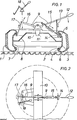
- a vehicle wheel in which the dismantling device is used, consists of the tire 1 to be dismantled, which is attached with its beads 2 to the radially inner circumference of a rigid, one-piece rim 3.
- the beads 2 which contain tensile and pressure-resistant core rings 4 ), are located on axially parallel or slightly inclined rim seat surfaces 5, which lie next to radially inwardly extending rim flanges 6.
- the rim seat surfaces 5 are joined by a high assembly bed 7, which is characterized by a diameter which is substantially larger than that of the seat surfaces 5 and in the area of which the wheel disc 8 of the rim 3 is located.
- a tire dismantling device in which a toggle lever 9 is fastened to a support frame 10, is first placed on a horizontally lying vehicle wheel.
- a centering element 11 on the support frame 10 can be used for exact positioning, and means for fixing can be present.
- a removal hook 17 is articulated on the load arm 16 of the toggle lever 9. In the vicinity of this hook 17 there can be a smaller additional toggle lever 18 attached to the support frame 10.
- the distance between the disassembly hook 17 and the auxiliary toggle lever 18 should be selected such that both with the wheel axle an angle of about 15 0th
- the lengths of the operating arm 12 and the load arm 16, push rod 13, compensating spring 15 (with rod) and dismantling hook 17 and the fastening points of the push rod 13, the compensating spring 15 and the dismantling hook 16 are coordinated with one another in such a way that the following sequence of movements when the operating arm 12 is depressed takes place.
- the dismantling spoon 14 is pressed against the tire bead 2 or the lower tire side wall in the region of the rim flange 6.
- a section of the tire bead 2 is gradually shifted into the high assembly bed 7.
- the dismantling hook 17 comes into engagement on the opposite bead section, which has meanwhile loosened from its seat surface 5, and as the operating arm 12 continues to move downward, the assembly hook 17 pulls the second bead section in a manner that protects the bead via the rim flange 6.
- the additional toggle lever 18 can be used, with which the dismantled peripheral section of the bead 2 is enlarged so much that the entire bead 2 can be easily pulled from the rim 3 by hand or with other aids.
- FIG. 3 schematically shows an embodiment in which, instead of a dismantling spoon, a drivable roller 19 engages a first bead section and presses it into the high assembly bed 7.
- a drivable roller 19 engages a first bead section and presses it into the high assembly bed 7.
- a dismantling hook 17 can again engage, which, for. B. is hydraulically actuated and, like the drivable roller 19, can be integrated into a mounting device.
Landscapes
- Engineering & Computer Science (AREA)
- Mechanical Engineering (AREA)
- Tires In General (AREA)
- Vehicle Cleaning, Maintenance, Repair, Refitting, And Outriggers (AREA)
- Separation, Recovery Or Treatment Of Waste Materials Containing Plastics (AREA)
Applications Claiming Priority (2)
| Application Number | Priority Date | Filing Date | Title |
|---|---|---|---|
| DE3428010 | 1984-07-28 | ||
| DE19843428010 DE3428010A1 (de) | 1984-07-28 | 1984-07-28 | Verfahren und vorrichtung zur demontage von fahrzeugluftreifen |
Publications (2)
| Publication Number | Publication Date |
|---|---|
| EP0170124A2 true EP0170124A2 (fr) | 1986-02-05 |
| EP0170124A3 EP0170124A3 (fr) | 1987-02-04 |
Family
ID=6241900
Family Applications (1)
| Application Number | Title | Priority Date | Filing Date |
|---|---|---|---|
| EP85108657A Ceased EP0170124A3 (fr) | 1984-07-28 | 1985-07-11 | Méthode et dispositif pour le démontage d'un pneumatique |
Country Status (7)
| Country | Link |
|---|---|
| US (1) | US4610287A (fr) |
| EP (1) | EP0170124A3 (fr) |
| JP (1) | JPS6141603A (fr) |
| CA (1) | CA1242636A (fr) |
| DE (1) | DE3428010A1 (fr) |
| ES (1) | ES8703112A1 (fr) |
| GR (1) | GR851908B (fr) |
Cited By (2)
| Publication number | Priority date | Publication date | Assignee | Title |
|---|---|---|---|---|
| EP0302220A3 (fr) * | 1987-08-07 | 1990-02-28 | Hofmann Werkstatt-Technik Gmbh | Dispositif de démontage de pneumatiques fixés sur une jante |
| DE19729416C2 (de) * | 1997-07-09 | 2002-03-07 | Snap On Deutschland Holding | Wulstniederhalter |
Families Citing this family (6)
| Publication number | Priority date | Publication date | Assignee | Title |
|---|---|---|---|---|
| DE3524664A1 (de) * | 1985-07-10 | 1987-01-22 | Hofmann Werkstatt Technik | Demontiervorrichtung fuer einen an einer radfelge befestigten reifen |
| DE8711330U1 (de) * | 1987-08-20 | 1987-10-01 | Weilnhammer Maschinenbau GmbH, 8250 Dorfen | Vorrichtung zur Demontage mindestens eines Reifens |
| JP5149189B2 (ja) * | 2005-10-06 | 2013-02-20 | アンドロイド インダストリーズ エルエルシー | タイヤ/ホイールビード混入物除去装置 |
| US7640963B2 (en) * | 2006-10-06 | 2010-01-05 | Android Industries Llc | Tire/wheel bead entrapment remover |
| CN110315918B (zh) * | 2019-05-08 | 2020-05-05 | 安徽字母表工业设计有限公司 | 车载车辆扒胎器 |
| CN113682094B (zh) * | 2021-09-23 | 2023-04-14 | 志研自动化设备湖北有限公司 | 一种轮胎拆装机 |
Family Cites Families (5)
| Publication number | Priority date | Publication date | Assignee | Title |
|---|---|---|---|---|
| US2915283A (en) * | 1954-06-17 | 1959-12-01 | Steelman Products Corp | Tire spreading tools |
| US3198362A (en) * | 1962-10-12 | 1965-08-03 | Harold I Berg | Lifting tool |
| US4462451A (en) * | 1981-04-20 | 1984-07-31 | Motor Wheel Corporation | Method and apparatus for removing tires from rims |
| DE3330316A1 (de) * | 1983-08-23 | 1985-03-07 | Continental Gummi-Werke Ag, 3000 Hannover | Montagevorrichtung fuer reifen |
| DE3334203A1 (de) * | 1983-09-22 | 1985-04-18 | Continental Gummi-Werke Ag, 3000 Hannover | Montagevorrichtung fuer fahrzeugluftreifen |
-
1984
- 1984-07-28 DE DE19843428010 patent/DE3428010A1/de not_active Withdrawn
-
1985
- 1985-07-11 EP EP85108657A patent/EP0170124A3/fr not_active Ceased
- 1985-07-23 US US06/758,168 patent/US4610287A/en not_active Expired - Fee Related
- 1985-07-24 ES ES545524A patent/ES8703112A1/es not_active Expired
- 1985-07-25 CA CA000487488A patent/CA1242636A/fr not_active Expired
- 1985-07-26 JP JP16420185A patent/JPS6141603A/ja active Pending
- 1985-08-05 GR GR851908A patent/GR851908B/el unknown
Cited By (2)
| Publication number | Priority date | Publication date | Assignee | Title |
|---|---|---|---|---|
| EP0302220A3 (fr) * | 1987-08-07 | 1990-02-28 | Hofmann Werkstatt-Technik Gmbh | Dispositif de démontage de pneumatiques fixés sur une jante |
| DE19729416C2 (de) * | 1997-07-09 | 2002-03-07 | Snap On Deutschland Holding | Wulstniederhalter |
Also Published As
| Publication number | Publication date |
|---|---|
| ES545524A0 (es) | 1987-02-16 |
| GR851908B (fr) | 1985-11-26 |
| CA1242636A (fr) | 1988-10-04 |
| DE3428010A1 (de) | 1986-01-30 |
| ES8703112A1 (es) | 1987-02-16 |
| US4610287A (en) | 1986-09-09 |
| EP0170124A3 (fr) | 1987-02-04 |
| JPS6141603A (ja) | 1986-02-28 |
Similar Documents
| Publication | Publication Date | Title |
|---|---|---|
| DE69505972T2 (de) | Verfahren zum zusammenbau einer anordnung von reifen und notlaufstützring | |
| DE602005005103T2 (de) | Automatische Radmontier- und Demontiervorrichtung | |
| DE2036914A1 (de) | Behalter und Verfahren zu dessen Herstellung | |
| EP0170124A2 (fr) | Méthode et dispositif pour le démontage d'un pneumatique | |
| DE3243289A1 (de) | Werkzeug zur montage von reifen | |
| DE2522749A1 (de) | Luftreifen-transportvorrichtung | |
| DE1148897B (de) | Felge fuer schlauchlose Reifen | |
| DE1962227A1 (de) | Fahrzeugrad und Verfahren und Geraet fuer den Zusammenbau desselben | |
| EP0191367B1 (fr) | Méthode et dispositif pour le montage d'un pneumatique de roues de véhicule automobile | |
| DE1194130B (de) | Einrichtung zum Beschicken von Vulkanisierpressen mit Vulkanisierformen mit Schliessringen oder Verschlussteilen fuer die Laufflaechenerneuerung von Fahrzeugluftreifen | |
| DE7801656U1 (de) | Vorrichtung zum runderneuern von luftreifen | |
| DE60118997T2 (de) | Verfahren zur Herstellung eines Reifenwulstkernes mit einem verankerten hinteren Ende | |
| DE626767C (de) | Bereifungskoerper fuer Fahrzeugraeder mit zwei oder mehreren selbstaendigen Karkassen | |
| DE69933482T2 (de) | Reifen mit abgerundeter Wulstzehe und Form zum Formen des Reifens | |
| DE602004013086T2 (de) | Verbessertes Verfahren zum wechseln der Lauffläche eines sehr breiten Reifens | |
| DE2224886A1 (de) | Vorrichtung zum Aufziehen von Fahr zeugreifen | |
| DE1038931B (de) | Reifen zur Anbringung an landwirtschaftliche Geraeteraeder | |
| DE558610C (de) | Verfahren zur Herstellung von schlauchlosen Luftradreifen | |
| EP0243785A2 (fr) | Méthode et dispositif pour le montage ou le démontage d'un bandage plein ou d'un pneumatique | |
| DE3411433C2 (fr) | ||
| DE3524664C2 (fr) | ||
| DE2359044A1 (de) | Verfahren zum auswechseln des laufguertels eines luftreifens | |
| DE3520801A1 (de) | Verfahren und vorrichtung zur demontage von fahrzeugluftreifen | |
| DE77300C (de) | Schutz- und Befestigungsmantel mit Verschnürung für Luftradreifen | |
| DE2934914A1 (de) | Reifenmontagevorrichtung und verfahren zu ihrer verwendung |
Legal Events
| Date | Code | Title | Description |
|---|---|---|---|
| PUAI | Public reference made under article 153(3) epc to a published international application that has entered the european phase |
Free format text: ORIGINAL CODE: 0009012 |
|
| AK | Designated contracting states |
Designated state(s): AT BE CH DE FR GB IT LI LU NL SE |
|
| PUAL | Search report despatched |
Free format text: ORIGINAL CODE: 0009013 |
|
| AK | Designated contracting states |
Kind code of ref document: A3 Designated state(s): AT BE CH DE FR GB IT LI LU NL SE |
|
| 17P | Request for examination filed |
Effective date: 19870113 |
|
| STAA | Information on the status of an ep patent application or granted ep patent |
Free format text: STATUS: EXAMINATION IS IN PROGRESS |
|
| 17Q | First examination report despatched |
Effective date: 19871123 |
|
| 18R | Application refused |
Effective date: 19880613 |
|
| RIN1 | Information on inventor provided before grant (corrected) |
Inventor name: BOLTZE, CARSTEN, DIPL.-ING. Inventor name: RACH, HEINZ-DIETER, DIPL.-ING. Inventor name: FRERICHS, UDO, DIPL.-ING. Inventor name: KLOSE, HANS-ULRICH, DIPL.-ING. |