EP0170170B1 - Lagenwicklung für Transformatoren - Google Patents
Lagenwicklung für Transformatoren Download PDFInfo
- Publication number
- EP0170170B1 EP0170170B1 EP85109066A EP85109066A EP0170170B1 EP 0170170 B1 EP0170170 B1 EP 0170170B1 EP 85109066 A EP85109066 A EP 85109066A EP 85109066 A EP85109066 A EP 85109066A EP 0170170 B1 EP0170170 B1 EP 0170170B1
- Authority
- EP
- European Patent Office
- Prior art keywords
- winding
- layer
- lead
- region
- insulating wall
- Prior art date
- Legal status (The legal status is an assumption and is not a legal conclusion. Google has not performed a legal analysis and makes no representation as to the accuracy of the status listed.)
- Expired
Links
Images


Classifications
-
- H—ELECTRICITY
- H01—ELECTRIC ELEMENTS
- H01F—MAGNETS; INDUCTANCES; TRANSFORMERS; SELECTION OF MATERIALS FOR THEIR MAGNETIC PROPERTIES
- H01F27/00—Details of transformers or inductances, in general
- H01F27/28—Coils; Windings; Conductive connections
- H01F27/2823—Wires
- H01F27/2828—Construction of conductive connections, of leads
-
- H—ELECTRICITY
- H01—ELECTRIC ELEMENTS
- H01F—MAGNETS; INDUCTANCES; TRANSFORMERS; SELECTION OF MATERIALS FOR THEIR MAGNETIC PROPERTIES
- H01F27/00—Details of transformers or inductances, in general
- H01F27/28—Coils; Windings; Conductive connections
- H01F27/32—Insulating of coils, windings, or parts thereof
- H01F27/323—Insulation between winding turns, between winding layers
Definitions
- the invention relates to a layer winding for transformers with end-side, additional insulation for winding conductor insulation having rejections from winding layers flanked radially on both sides by further winding layers and with cooling channels separated between the winding layers by an insulating wall and kept open radially one above the other by spacer strips.
- thicker spacer strips or oil channel strips adapted to the dimensions of the diversions have usually been provided on the entire winding circumference in order to lead out the reinforced insulated leads, in particular from inner winding layers, in order to ensure a sufficient flow of cooling oil.
- the use of the thicker spacer bars causes diameter increases on the winding structure and thus weight increases with the consequence of an increased material consumption and with increasing transport dimensions.
- the invention is therefore based on the object to improve the structure of layer windings of the type mentioned in such a way that the cross-sectional area claimed by the winding becomes smaller than in the previously conventional structure, but the safe dissipation of the heat losses generated from the winding must also be ensured like the circular cross-sectional shape of the individual winding layers which is essential for the short-circuit strength.
- Expedient embodiments of the invention consist in that the insulating walls are curved in the same direction at every point of the diversion area as in the normal circumferential area and that the additional insulation of each of the diversions is continued in the circumferential direction over two or more spacer strips on the first turn of the winding layer and that the deviations from the circular shape in the cross section of the insulating walls, including the transition zones, extend over several spacer strips in the circumferential direction of the winding.
- the insulating walls consist of paper webs which are wound onto one another and glued to one another point by point, one end of each spacer strip is glued to the adjacent insulating wall, and the additional insulation of the leads is more elastic in itself than the insulating walls and the winding layers.
- the winding structure according to the invention is very advantageous because, by not having to reinforce the cooling channels flanking the winding layers with leads, it leads to a smaller overall cross-section of the winding arrangement and thus also to smaller overall dimensions of the transformer, and because the winding arrangement according to the invention also surprisingly ensures compliance with the short-circuit voltage is advantageously influenced.
- Radially above the winding layer 1 are connected, for example, with diverters, not shown Winding layers 2 and 3.
- an insulating wall 4 is provided in each case, which separates axially parallel cooling channels 5 from one another.
- the cooling channels 5 are kept open by spacer strips 7.
- the winding conductor ends of the last turn of each of the winding layers 1, 2 and 3 are led out of the winding arrangement in the form of axles 8.
- the leads 8 carry an additional insulation 9 above the normal winding conductor insulation, which is usually designed for the full rated voltage of the transformer.
- the additional insulation 9 extends into the respective end turn of the associated winding layer 1, 2 or 3 and is held there by, for example, three pairs of spacer strips 7.
- the thickness of the additional insulation 9 is at nominal voltages from 200 kV in the order of magnitude of the thickness of the spacer strips 7, so that the exit of the cooling channels 5 in the area of the diversion 8 would be practically closed without special measures in the region of the diversion 8 via approximately two or more sectors formed by spacer strips 7.
- the aim is to maintain the circular cross-sectional shape.
- the spacer strips 7 have so far been made reinforced over the entire winding circumference wherever they clamp a winding layer provided with a lead-out 8.
- the special spacer strips 7 ' are now reinforced, which abut one end of an additional insulation 9.
- These reinforced special spacer strips 7 ' have a shoulder 6 at their end abutting the additional insulation 9, by means of which they are adapted to the additional insulation 9 protruding into the cooling channel 5.
- the special spacer strips 7 'which are supported on the reinforced special spacer strips 7' via the insulating wall 4 are designed to be correspondingly weaker than the spacer strips 7 in the normal circumferential range.
- the special spacer strips 7 ' are optionally also made in different thicknesses within the diversion area.
- This variation in the thickness of the special spacer strips 7 'maintains the annular cross section for the winding layers 1, 2 and 3, but abandons them for the insulating walls 4 which bulge from the respective winding layer 1, 2 or 3 in the area of the outlets 8.
- This arrangement therefore makes it possible to maintain the normal layer spacing even for winding layers with reinforced insulated leads 8 and thus ensures very good use of space.
- this arrangement surprisingly also has a very advantageous influence on the short-circuit voltage.
Landscapes
- Engineering & Computer Science (AREA)
- Power Engineering (AREA)
- Insulating Of Coils (AREA)
- Coils Or Transformers For Communication (AREA)
- Coils Of Transformers For General Uses (AREA)
Description
- Die Erfindung betrifft eine Lagenwicklung für Transformatoren mit stirnseitigen, eine Zusatzisolierung zur Wickelleiterisolierung aufweisenden Ausleitungen aus radial auf beiden Seiten von weiteren Wicklungslagen flankierten Wicklungslagen und mit zwischen den Wicklungslagen durch eine Isolierwand voneinander getrennten, radial übereinanderliegenden durch Distanzleisten offengehaltenen Kühlkanälen.
- Derartige Lagenwicklungen sind durch die DE-A-22 46 398 bekannt.
- Darüber hinaus sind durch die DE-A-30 35 262 für Transformatorlagenwicklungen verstärkt isolierte Ausleitungen bekannt, deren verstärkte Isolierung aus unverleimt aufeinandergewickelten Kreppapierlagen besteht, die zusammen mit dem Ausleitungsleiter faltenfrei abgebogen werden können.
- Zum Herausführen der verstärkt isolierten Ausleitungen, insbesondere von innenliegenden Wicklungslagen, werden bisher üblicherweise am ganzen Wicklungsumfang dickere, den Abmessungen der Ausleitungen angepaßte Distanz- oder Ölkanalleisten vorgesehen, um einen ausreichenden Kühlölfluß zu gewährleisten. Die Verwendung der dickeren Distanzleisten verursacht Durchmesser vergrößerungen am Wicklungsaufbau und dadurch Gewichtserhöhungen mit der Folge eines erhöhten Werkstoffverbrauchs und mit steigenden Transportabmessungen.
- Der Erfindung liegt daher die Aufgabe zugrunde, den Aufbau von Lagenwicklungen der eingangs genannten Art so zu verbessern, daß die von der Wicklung beanspruchte Querschnittsfläche kleiner wird als bei bisher üblichem Aufbau, wobei jedoch die sichere Abführung der entstehenden Verlustwärme aus der Wicklung ebenso gewährleistet bleiben muß wie die für die Kurzschlußfestigkeit wesentliche kreisringförmige Querschnittsform der einzelnen Wicklungslagen.
- Diese Aufgabe wird erfindungsgemäß dadurch gelöst,
- - daß die jeweils eine Ausleitung flankierenden Isolierwände im Bereich dieser Ausleitung von der diese tragenden Wicklungslage durch besondere Distanzleisten über ihre gesamte axiale Länge radial nach innen oder nach außen abgewölbt sind,
- - daß die Isolierwände hierdurch im Gegensatz zu der im Querschnitt ihre Kreisringform behaltenden Wicklungslage von ihrem im übrigen ebenfalls kreisringförmigen Querschnitt abweichen,
- - daß der kleinste Abstand zwischen der Isolierwand und der Zusatzisolierung der Ausleitung in deren Bereich zwar kleiner ist als die lichte Weite zwischen der Isolierwand und der benachbarten Wicklungslage in diesem Bereich, jedoch mindestens halb so groß ist wie die lichte Weite zwischen der Isolierwand und der benachbarten Wicklungslage außerhalb dieses Bereiches und
- - daß die Summe der der lichten Weite entsprechenden radialen Dicke der dieselbe Isolierwand von innen und von außen flankierenden Diatanzleisten im Normalumfangsbereich und im Ausleitungsbereich gleich ist, wobei die stärkeren besonderen Distanzleisten an ihrem an der Zusatzisolierung der Ausleitung anliegenden Ende in ihrer Dicke um die Dicke der Zusatzisolierung abgesetzt sind.
- Zweckmä59ige Ausgesaltungen der Erfindung bestehen darin, daß die Isolierwände auch an jeder Stelle des Ausleitungsbereiches in gleicher Richtung gekrümmt sind wie im Normalumfangsbereich und daß die Zusatzisolierung jeder der Ausleitungen jeweils über zwei oder mehrere Distanzleisten in Umfangsrichtung auf der ersten Windung der Wicklungslage fortgesetzt ist und daß sich die Abweichungen von der Kreisform im Querschnitt der Isolierwände einschließlich der Übergangszonen je Ausleitung über mehrere Distanzleisten in Umfangsrichtung der Wicklung erstrecken.
- Nach weiteren vorteilhaften Ausgestaltungsmerkmalen der Erfindung bestehen die Isolierwände aus aufeinandergewickelten und punktweise miteinander verklebten Papierbahnen, ist jeweils ein Ende jeder Distanzleiste mit der anliegenden Isolierwand verklebt und ist die Zusatzisolierung der Ausleitungen in sich elastischer als die Isolierwände und die Wicklungslagen.
- Der erfindungsgemäße Wicklungsaufbau ist sehr vorteilhaft, weil er durch den Verzicht auf eine Verstärkung der die Wicklungslagen mit Ausleitungen flankierenden Kühlkanäle zu einem kleineren Gesamtquerschnitt der Wicklungsanordnung und damit auch zu kleineren Gesamtabmessungen des Transformators führt und weil darüber hinaus überraschenderweise durch die erfindungsgemäße Wicklungsanordnung die Einhaltung der Kurzschlußspannung vorteilhaft beeinflußt ist.
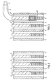
- Ein Ausführungsbeispiel der Erfindung wird anhand einer Zeichnung näher erläutert. Es zeigen:
- Fig. 1 einen Ausschnitt aus einer Draufsicht von drei Wicklungslagen in stark verkleinertem Maßstab und
- Fig. 2 bis 5 Schnitte durch die Stirnseiten dieser drei Wicklungslagen entlang der Linien II-II, III-III, IV-IV und V-V in Fig. 1 in weniger stark verkleinertem Maßstab.
- Einander entsprechende Bauteile sind in allen Figuren mit gleichen Bezugszeichen versehen.
- Eine Transformatorlagenwicklung mit einer Vielzahl von nicht dargestellten Wicklungslagen ist radial nach außen durch eine oberste Wicklungslage 1 abgeschlossen. Radial über der Wicklungslage 1 liegen beispielsweise mit nicht dargestellten Umstellern verbundene Wicklungslagen 2 und 3. Zwischen den jeweils radial aufeinanderfolgenden Wicklungslagen 1, 2 und 3 ist je eine Isolierwand 4 vorgesehen, die achsparallele Kühlkanäle 5 voneinander trennt. Die Kühlkanäle 5 sind durch Distanzleisten 7 offengehalten.
- Die Wickelleiterenden der jeweils letzten Windung jeder der Wicklungslagen 1, 2 und 3 sind als Ausleitungen 8 achsparallel aus der Wicklungsanordnung herausgeführt. Die Ausleitungen 8 tragen über der normalen Wickelleiterisolierung eine Zusatzisolierung 9, die üblicherweise für die volle Nennspannung des Transformators ausgelegt ist. Die Zusatzisolierung 9 erstreckt sich bis in die jeweilige Endwindung der zugehörigen Wicklungslage 1, 2 oder 3 und wird dort von beispielsweise drei Paar Distanzleisten 7 gehalten.
- Die Dicke der Zusatzisolierung 9 liegt bei Nennspannungen ab 200 kV in der Größenordnung der Dicke der Distanzleisten 7, so daß der Ausgang der Kühlkanäle 5 in dem Bereich der Ausleitung 8 über etwa zwei oder mehr von Distanzleisten 7 gebildeten Sektoren ohne besondere Maßnahmen praktisch verschlossen wäre. Zur Beherrschung der an der Wicklung auftretenden Kurzschlußkräfte ist für diese eine Beibehaltung der kreisringförmigen Querschnittsform anzustreben. Aus diesem Grund werden bisher die Distanzleisten 7 überall dort über den gesamten Wicklungsumfang verstärkt ausgeführt, wo sie eine mit einer Ausleitung 8 versehene Wicklungslage einspannen.
- Erfindungsgemäß sind nun lediglich die besonderen Distanzleisten 7' verstärkt, die mit einem ihrer Enden an einer Zusatzisolierung 9 anliegen. Diese verstärkten besonderen Distanzleisten 7' weisen an ihrem an der Zusatzisolierung 9 anliegenden Ende einen Absatz 6 auf, durch den sie an die in den Kühlkanal 5 vorstehende Zusatzisolierung 9 angepaßt sind. Dagegen sind die sich über die Isolierwand 4 an den verstärkten besonderen Distanzleisten 7' abstützenden besonderen Distanzleisten 7' um ein entsprechendes Maß schwächer als die Distanzleisten 7 im Normalumfangsbereich ausgeführt. Zur Beibehaltung der Krümmungsrichtung der Isolierwände 4 sind die besonderen Distanzleisten 7' gegebenenfalls auch innerhalb des Ausleitungsbereiches in unterschiedlichen Dicken ausgeführt.
- Durch diese Variation der Dicke der besonderen Distanzleisten 7' wird zwar der kreisringförmige Querschnitt für die Wicklungslagen 1, 2 und 3 beibehalten, jedoch für die im Bereich der Ausleitungen 8 jeweils von der betreffenden Wicklungslage 1, 2 oder 3 abgewölbten Isolierwände 4 aufgegeben. Diese Anordnung ermöglicht daher auch für Wicklungslagen mit verstärkt isolierten Ausleitungen 8 eine Beibehaltung des normalen Lagenabstandes und gewährleistet dadurch eine sehr gute Raumausnutzung. Daneben hat diese Anordnung überraschenderweise auch einen sehr vorteilhaften Einfluß auf die Kurzschlußspannung.
Claims (6)
dadurch gekennzeichnet,
Priority Applications (1)
| Application Number | Priority Date | Filing Date | Title |
|---|---|---|---|
| AT85109066T ATE30650T1 (de) | 1984-08-02 | 1985-07-19 | Lagenwicklung fuer transformatoren. |
Applications Claiming Priority (2)
| Application Number | Priority Date | Filing Date | Title |
|---|---|---|---|
| DE3428613 | 1984-08-02 | ||
| DE19843428613 DE3428613A1 (de) | 1984-08-02 | 1984-08-02 | Lagenwicklung fuer transformatoren |
Publications (2)
| Publication Number | Publication Date |
|---|---|
| EP0170170A1 EP0170170A1 (de) | 1986-02-05 |
| EP0170170B1 true EP0170170B1 (de) | 1987-11-04 |
Family
ID=6242255
Family Applications (1)
| Application Number | Title | Priority Date | Filing Date |
|---|---|---|---|
| EP85109066A Expired EP0170170B1 (de) | 1984-08-02 | 1985-07-19 | Lagenwicklung für Transformatoren |
Country Status (4)
| Country | Link |
|---|---|
| EP (1) | EP0170170B1 (de) |
| AT (1) | ATE30650T1 (de) |
| BR (1) | BR8503642A (de) |
| DE (2) | DE3428613A1 (de) |
Families Citing this family (2)
| Publication number | Priority date | Publication date | Assignee | Title |
|---|---|---|---|---|
| DK64690D0 (da) * | 1990-03-12 | 1990-03-12 | Ntp Elektronik A S | Omkoblingssystem |
| EP2472533A1 (de) * | 2011-01-04 | 2012-07-04 | ABB Technology AG | Transformatorwicklung mit Kühlkanal |
Family Cites Families (4)
| Publication number | Priority date | Publication date | Assignee | Title |
|---|---|---|---|---|
| DE2246398C3 (de) * | 1972-09-21 | 1978-06-22 | Transformatoren Union Ag, 7000 Stuttgart | Oberspannungsstammlagenwicklung hoher Spannung für Transformatoren, Drosselspulen u.dgl |
| DE2361220C3 (de) * | 1973-12-08 | 1979-01-25 | Transformatoren Union Ag, 7000 Stuttgart | Isolieranordnung für Ausleitungen von Hochspannungswicklungen in T ransformatoren und Drosseln |
| DE3035262C2 (de) * | 1980-09-18 | 1983-09-22 | Transformatoren Union Ag, 7000 Stuttgart | Wicklung für Transformatoren mit großer Nennleistung |
| DE3101217C2 (de) * | 1981-01-16 | 1984-08-23 | Smit Transformatoren B.V., Nijmegen | Wicklung für einen Trockentransformator mit Abstandshalteanordnung |
-
1984
- 1984-08-02 DE DE19843428613 patent/DE3428613A1/de not_active Withdrawn
-
1985
- 1985-07-19 AT AT85109066T patent/ATE30650T1/de not_active IP Right Cessation
- 1985-07-19 DE DE8585109066T patent/DE3560927D1/de not_active Expired
- 1985-07-19 EP EP85109066A patent/EP0170170B1/de not_active Expired
- 1985-08-01 BR BR8503642A patent/BR8503642A/pt not_active IP Right Cessation
Also Published As
| Publication number | Publication date |
|---|---|
| ATE30650T1 (de) | 1987-11-15 |
| DE3428613A1 (de) | 1986-02-13 |
| EP0170170A1 (de) | 1986-02-05 |
| DE3560927D1 (en) | 1987-12-10 |
| BR8503642A (pt) | 1986-05-06 |
Similar Documents
| Publication | Publication Date | Title |
|---|---|---|
| DE3243595C2 (de) | Wicklungsanordnung für einen gasgekühlten Transformator | |
| DE2236854C2 (de) | Abstandshalter für gasisolierte Hochspannungskabel | |
| EP1315182A2 (de) | Wicklung für einen Transformator oder eine Spule | |
| EP0170170B1 (de) | Lagenwicklung für Transformatoren | |
| EP0049382B1 (de) | Wicklungsanordnung für Transformatoren mit quadratischem Kernquerschnitt | |
| DE2505085C2 (de) | Zylinderwicklung für Hochspannungstransformatoren | |
| DE2418230C3 (de) | Kapazitiv gesteuerte Hochspannungswicklung aus Scheibenspulen für Transformatoren mit großen Leistungen | |
| DE3022070C2 (de) | Schirmkörper für bewickelte Kernschenkel von Transformatoren, Drosselspulen u.dgl. | |
| DE1413549B2 (de) | Hochspannungslagenwicklung mit inneneingang fuer trans formatoren und drosselspulen | |
| EP2330603A1 (de) | Transformator mit Bandwicklung | |
| DE19608289C2 (de) | Aus Scheibenspulen bestehende Hochspannungswicklung für Transformatoren und Drosselspulen | |
| EP2863402A1 (de) | Bandwicklung für Hochspannungstransformatoren | |
| DE2627314C2 (de) | Wicklung für Transformatoren | |
| DE2246398B2 (de) | Oberspannungsstammlagenwicklung hoher spannung fuer transformatoren, drosselspulen u.dgl. | |
| DE2535321C3 (de) | Transformator für hohe Spannung | |
| EP0058232A1 (de) | Scheibenspulenwicklung aus ineinandergewickelten Einzel- oder Doppelspulen | |
| DE1413549C (de) | Hochspannungslagenwicklung mit Inneneingang für Transformatoren und Drosselspulen | |
| DE1513962C3 (de) | Lagenwicklung in Mehrfachlagenschaltung für Transformatoren und Drosselspulen mit keilförmiger Isolation | |
| DE4236975C2 (de) | Stufenwicklung für Transformatoren und Drosselspulen | |
| DE2019103C3 (de) | Aus Doppellagen bestehende Wicklung für Transformatoren und Drosselspulen | |
| DD286451A5 (de) | Lagenwicklung fuer transformatoren mit stirnseitigen, eine zusatzisolierung aufweisenden ausleitungen | |
| DE2716057A1 (de) | Transformator | |
| EP0088934A1 (de) | Scheibenspulenwicklung aus ineinandergewickelten Einzel- oder Doppelspulen | |
| DD222725A1 (de) | Schild zur blitzspannungssteuerung in lagenwicklungen von transformatoren | |
| DD143975B1 (de) | Ausleitungsanordnung fuer lagenwicklungen von transformatoren und drosselspulen |
Legal Events
| Date | Code | Title | Description |
|---|---|---|---|
| PUAI | Public reference made under article 153(3) epc to a published international application that has entered the european phase |
Free format text: ORIGINAL CODE: 0009012 |
|
| AK | Designated contracting states |
Designated state(s): AT CH DE GB LI NL SE |
|
| 17P | Request for examination filed |
Effective date: 19860226 |
|
| RAP1 | Party data changed (applicant data changed or rights of an application transferred) |
Owner name: TRANSFORMATOREN UNION AKTIENGESELLSCHAFT |
|
| 17Q | First examination report despatched |
Effective date: 19870120 |
|
| GRAA | (expected) grant |
Free format text: ORIGINAL CODE: 0009210 |
|
| RAP1 | Party data changed (applicant data changed or rights of an application transferred) |
Owner name: SIEMENS AKTIENGESELLSCHAFT BERLIN UND MUENCHEN |
|
| AK | Designated contracting states |
Kind code of ref document: B1 Designated state(s): AT CH DE GB LI NL SE |
|
| REF | Corresponds to: |
Ref document number: 30650 Country of ref document: AT Date of ref document: 19871115 Kind code of ref document: T |
|
| REF | Corresponds to: |
Ref document number: 3560927 Country of ref document: DE Date of ref document: 19871210 |
|
| GBT | Gb: translation of ep patent filed (gb section 77(6)(a)/1977) | ||
| PLBE | No opposition filed within time limit |
Free format text: ORIGINAL CODE: 0009261 |
|
| STAA | Information on the status of an ep patent application or granted ep patent |
Free format text: STATUS: NO OPPOSITION FILED WITHIN TIME LIMIT |
|
| 26N | No opposition filed | ||
| PGFP | Annual fee paid to national office [announced via postgrant information from national office to epo] |
Ref country code: SE Payment date: 19920728 Year of fee payment: 8 |
|
| PGFP | Annual fee paid to national office [announced via postgrant information from national office to epo] |
Ref country code: NL Payment date: 19920731 Year of fee payment: 8 |
|
| PGFP | Annual fee paid to national office [announced via postgrant information from national office to epo] |
Ref country code: DE Payment date: 19920915 Year of fee payment: 8 |
|
| PGFP | Annual fee paid to national office [announced via postgrant information from national office to epo] |
Ref country code: CH Payment date: 19921022 Year of fee payment: 8 |
|
| PGFP | Annual fee paid to national office [announced via postgrant information from national office to epo] |
Ref country code: GB Payment date: 19930618 Year of fee payment: 9 |
|
| PGFP | Annual fee paid to national office [announced via postgrant information from national office to epo] |
Ref country code: AT Payment date: 19930623 Year of fee payment: 9 |
|
| PG25 | Lapsed in a contracting state [announced via postgrant information from national office to epo] |
Ref country code: SE Effective date: 19930720 |
|
| PG25 | Lapsed in a contracting state [announced via postgrant information from national office to epo] |
Ref country code: LI Effective date: 19930731 Ref country code: CH Effective date: 19930731 |
|
| PG25 | Lapsed in a contracting state [announced via postgrant information from national office to epo] |
Ref country code: NL Effective date: 19940201 |
|
| NLV4 | Nl: lapsed or anulled due to non-payment of the annual fee | ||
| REG | Reference to a national code |
Ref country code: CH Ref legal event code: PL |
|
| PG25 | Lapsed in a contracting state [announced via postgrant information from national office to epo] |
Ref country code: DE Effective date: 19940401 |
|
| PG25 | Lapsed in a contracting state [announced via postgrant information from national office to epo] |
Ref country code: GB Effective date: 19940719 Ref country code: AT Effective date: 19940719 |
|
| EUG | Se: european patent has lapsed |
Ref document number: 85109066.2 Effective date: 19940210 |
|
| GBPC | Gb: european patent ceased through non-payment of renewal fee |
Effective date: 19940719 |