EP0170329A2 - Machine d'emballage - Google Patents
Machine d'emballage Download PDFInfo
- Publication number
- EP0170329A2 EP0170329A2 EP85201209A EP85201209A EP0170329A2 EP 0170329 A2 EP0170329 A2 EP 0170329A2 EP 85201209 A EP85201209 A EP 85201209A EP 85201209 A EP85201209 A EP 85201209A EP 0170329 A2 EP0170329 A2 EP 0170329A2
- Authority
- EP
- European Patent Office
- Prior art keywords
- sealing
- tube
- holder
- packing
- accordance
- Prior art date
- Legal status (The legal status is an assumption and is not a legal conclusion. Google has not performed a legal analysis and makes no representation as to the accuracy of the status listed.)
- Granted
Links
- 238000012856 packing Methods 0.000 title claims abstract description 107
- 238000007789 sealing Methods 0.000 claims abstract description 152
- 239000000463 material Substances 0.000 claims abstract description 83
- 238000000034 method Methods 0.000 claims abstract description 25
- 238000006243 chemical reaction Methods 0.000 claims description 7
- 230000000694 effects Effects 0.000 claims description 3
- 230000002093 peripheral effect Effects 0.000 claims description 2
- 238000004519 manufacturing process Methods 0.000 abstract description 5
- 230000000284 resting effect Effects 0.000 abstract description 2
- 238000007493 shaping process Methods 0.000 abstract 1
- 239000007789 gas Substances 0.000 description 13
- 238000010276 construction Methods 0.000 description 4
- 239000000123 paper Substances 0.000 description 3
- 229920001169 thermoplastic Polymers 0.000 description 3
- 239000004416 thermosoftening plastic Substances 0.000 description 3
- MHAJPDPJQMAIIY-UHFFFAOYSA-N Hydrogen peroxide Chemical compound OO MHAJPDPJQMAIIY-UHFFFAOYSA-N 0.000 description 2
- 239000005030 aluminium foil Substances 0.000 description 2
- 239000011261 inert gas Substances 0.000 description 2
- 239000007788 liquid Substances 0.000 description 2
- 239000003566 sealing material Substances 0.000 description 2
- 230000000844 anti-bacterial effect Effects 0.000 description 1
- 230000004888 barrier function Effects 0.000 description 1
- 238000001816 cooling Methods 0.000 description 1
- 230000003292 diminished effect Effects 0.000 description 1
- 238000006073 displacement reaction Methods 0.000 description 1
- 230000003670 easy-to-clean Effects 0.000 description 1
- 229920001971 elastomer Polymers 0.000 description 1
- 230000001788 irregular Effects 0.000 description 1
- 239000008267 milk Substances 0.000 description 1
- 210000004080 milk Anatomy 0.000 description 1
- 235000013336 milk Nutrition 0.000 description 1
- 239000004033 plastic Substances 0.000 description 1
- 229920003023 plastic Polymers 0.000 description 1
- 229920000573 polyethylene Polymers 0.000 description 1
- 229920002379 silicone rubber Polymers 0.000 description 1
- 239000004945 silicone rubber Substances 0.000 description 1
- BFKJFAAPBSQJPD-UHFFFAOYSA-N tetrafluoroethene Chemical group FC(F)=C(F)F BFKJFAAPBSQJPD-UHFFFAOYSA-N 0.000 description 1
- 239000012815 thermoplastic material Substances 0.000 description 1
- 230000037303 wrinkles Effects 0.000 description 1
Images

Classifications
-
- B—PERFORMING OPERATIONS; TRANSPORTING
- B65—CONVEYING; PACKING; STORING; HANDLING THIN OR FILAMENTARY MATERIAL
- B65B—MACHINES, APPARATUS OR DEVICES FOR, OR METHODS OF, PACKAGING ARTICLES OR MATERIALS; UNPACKING
- B65B9/00—Enclosing successive articles, or quantities of material, e.g. liquids or semiliquids, in flat, folded, or tubular webs of flexible sheet material; Subdividing filled flexible tubes to form packages
- B65B9/10—Enclosing successive articles, or quantities of material, in preformed tubular webs, or in webs formed into tubes around filling nozzles, e.g. extruded tubular webs
- B65B9/20—Enclosing successive articles, or quantities of material, in preformed tubular webs, or in webs formed into tubes around filling nozzles, e.g. extruded tubular webs the webs being formed into tubes in situ around the filling nozzles
-
- B—PERFORMING OPERATIONS; TRANSPORTING
- B65—CONVEYING; PACKING; STORING; HANDLING THIN OR FILAMENTARY MATERIAL
- B65B—MACHINES, APPARATUS OR DEVICES FOR, OR METHODS OF, PACKAGING ARTICLES OR MATERIALS; UNPACKING
- B65B9/00—Enclosing successive articles, or quantities of material, e.g. liquids or semiliquids, in flat, folded, or tubular webs of flexible sheet material; Subdividing filled flexible tubes to form packages
- B65B9/10—Enclosing successive articles, or quantities of material, in preformed tubular webs, or in webs formed into tubes around filling nozzles, e.g. extruded tubular webs
- B65B9/13—Enclosing successive articles, or quantities of material, in preformed tubular webs, or in webs formed into tubes around filling nozzles, e.g. extruded tubular webs the preformed tubular webs being supplied in a flattened state
Definitions
- the present invention relates to a method on a packing machine of the type which converts a weblike packing material to packing containers through the conversion of the material web to a tube movable in downwards direction and repeated transverse flattening and sealing together of the same, the lower part of the tube being sealed off from its upper open end by means of a sealing unit.
- the invention also relates to an arrangement for the realization of the method on a packing machine of the type which converts tubular packing material to individual packing containers and comprises a sealing unit present in the tube which seals off a closed space in the lower end of the tube.
- Packing containers intended for example for milk or other liquid or semi-liquid foodstuffs are usually manufactured from laminated flexible packing material which comprises layers of paper, thermoplastics and aluminium foil.
- a known packing container is formed in that a web of the said packing laminate, whilst being fed through the packing machine, is successively converted to tubular shape in that its two longitudinal edges are joined together and sealed to one another in a liquid-tight manner.
- Subsequently contents are delivered in the required quantity to the lower end of the packing material tube which with the help of co-operating sealing jaws is then divided into individual packing containers separated from one another through repeated transverse sealings of the packing material tube and subsequent cutting.At the same time a certain forming process is carried out so that the finished packing containers obtain the desired, e.g. parallelepipedic, shape.
- a sealing unit is present in the packing material tube which is situated a little distance above the area where the transverse flattening and forming work of the material tube is taking place.
- the sealing unit is supported inside the tube by a filling pipe for the contents extending vertically through the tube.
- the sealing unit comprises a radially movable sealing holder with a peripheral sealing which rests against the inside of the material tube, the gaseous pressure medium which is delivered to the lower part of the tube acting so upon the sealing holder that the same is pressed against a sealing surface located above, against the effect of downwards directed forces on the sealing and the sealing holder.
- the sealing holder in accordance with the method which is the subject of the present invention so that it is radially movable, and balancing the downwards and upwards directed force on the sealing holder, a sealing function is obtained which is maintained also in cases of large lateral movements of the or the filling pipe packing material tube and under varying gas pressures in the lower part of the tube.
- the contact pressure between the sealing and the inside of the packing material tube can be maintained substantially constant around the whole periphery of the packing material tube and irrespectively of lateral movements of the material tube which previously had not been possible.
- the sealing unit comprises a stationary sealing guide situated in the tube which supports a movable sealing holder with a peripherally located annular sealing which rests against the inside of the material tube.
- the sealing unit in accordance with the invention with a sealing holder movable in lateral direction which in turn supports the peripherally located sealing, the sealing and the movable function of the unit have been separated from one another which means that each of the said parts for itself can be optimized for its particular task so as to give an improved overall result. Since the sealing holder participates in the necessary lateral movement, the flexibility of the seal, for example, needs no longer to be as great thus making it possible to select sealing material with improved characteristics, for example, from a point of view of wear.
- Fig.1 shows in principle the conversion of a weblike packing material to individual packing containers in a packing machine wherein use is made of the method and arrangement in accordance with the invention.
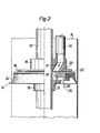
- Fig. 2 shows partly in section and on a larger scale a sealing unit in accordance with the invention as arranged on the packing machine according to fig.l.
- the packing machine shown in fig.l is of the previously known type which converts weblike packing material to individual packing containers.
- the packing material is a laminate which usually comprises a central carrier layer of paper which is covered on either side with thin, liquid-tight layers of thermoplastic material, e.g. polythene.
- thermoplastic material e.g. polythene.
- an aseptic packing laminate is used which beside the said layers of paper and plastics also comprises layers of gas barrier material e.g. aluminium foil.
- gas barrier material e.g. aluminium foil.
- the packing laminate Prior to the conversion to individual packing containers the packing laminate may pass through bactericidal arrangements, e.g. a bath containing hydrogen peroxide or the like, whereupon the conversion and filling can take place under aseptic conditions.
- This technique as well as the packing machines for its realization are well known to those versed in the art and no detailed description is required therefore in this context.
- the packing material is delivered to the packing machine 1 in the form of a roll 2 which is supported so that it can rotate in the magazine of the packing machine.
- the packing material web 3 moves via a number of guide rollers 4 up to the upper part of the machine where it passes over a deflection roller 5, thereafter to continue substantially vertically downwards through the packing machine.
- various folding and forming elements 6,7 arranged along the path of movement of the material web 3 the packing material web 3 during its downward movement through the machine is converted successively to tubular form in that its two longitudinal edges are guided towards each otheyand are sealed together so that a material tube 8 with a longitudinal, liquid-tight seal is produced.
- the sealing together of the two longitudinal edges takes place with the help of a supply of heat by means of a hot air nozzle 9, by means of which the parts of the thermoplastic layers situated at the edges are made to melt. Thereafter the two longitudinal edges are pressed together with simultaneous cooling which means that the thermoplastic layers are joined to one another so that the required, wholly liquid-tight, join, is obtained.
- the contents are then conducted to the lower end of the packing material tube 8 so formed via a filling pipe 10 which extends in through the upper open end of the packing material tube 8.
- the filling pipe then runs substantially concentrically downwards through the packing material tube and opens a little distance above this lower end.
- forming and sealing jaws 11,12 are arranged on either side of the packing material tube 8 which are adapted so as to process the packing material tube 8 in pairs between themselves.
- a further number of jaws is present which alternatingly process the packing material tube.
- the sealing jaws 12 are moved continuously to and fro in the direction towards and away from each other respectively so as to compress and seal the packing material tube 8 at uniform intervals along transverse sealing zones. At the same time the sealing jaws 12 are moved to and fro in vertical direction so that when they are in the upper end position they are moved towards one another and compress and retain the packing material tube. In the subsequent movement through the packing machine the walls of the packing material tube are compressed and welded to each other, the material tube being advanced at the same time over a distance which corresponds to the length of one packing container blank.
- the two forming jaws 11 are swung towards each other so that the part of the packing material tube 8 which is located directly above the sealing jaws 12 is partly compressed and formed to the desired shape, in this case substantially cushion shape with a rectangular cross-section.
- the sealing jaws 12 have reached their lower position the forming jaws 11 are swung out again at the same time as the material tube is severed by a transverse cut through the zone compressed by the sealing jaws.
- a packing container 13 formed previously will be detached from the packing material tube.
- the packing container 13 is passed on with the help of a conveyor (not shown) for continued processing and final forming so that a packing container of the required shape (in this case parallelepipedic) is produced.
- the desired contents are delivered to the lower end of the packing material tube 8 via the filling pipe 10.
- partly filled packing containers are produced either by delivering the contents continuously at such a rate that each individual packing container formed has been filled with the desired quantity when the delivery is interrupted by flattening and sealing of the tube or else by delivering the desired quantity of contents in portions as soon as a transverse sealing has been made in the tube.
- the packing machine therefore comprises a sealing unit 14 arranged around the filling pipe 10 placed at some distance from the opening of the filling pipe which seals off the lower end of the material tube from the surrounding atmosphere.
- the sealing unit 14 is supported by the filling pipe 10 and rests forming a seal against the same as well as against the inside of the packing material tube.
- a further continuous pipe 15 extends through the sealing unit for the delivery of gas, e.g. inert gas or air, to the lower closed end of the packing material tube.
- gas e.g. inert gas or air
- the gas delivery pipe 15 communicates with the space below the sealing unit and thus permits delivery of a suitable pressure medium to the lower part of the packing material tube 8 separated by the sealing unit which consequently can be maintained under a suitable pressure during the forming and flattening of the lower end of the tube.
- the delivery pipe 15 for pressure medium just as the filling pipe 10, enters through the upper open part of the packing material tube and thereafter extends downwards parallel with the filling pipe 10 through the packing material tube and the sealing unit 14.
- further pipes for the delivery of, for example, different types of contents etc. may likewise extend down through the material tube and pass the sealing unit 14. This is not shown, however, on the drawing.
- the sealing unit 14 comprises a sealing guide 16 divided into two parts, the upper and lower parts being connected to the filling pipe 10 in a suitable manner, e.g. with the help of a screw joint not shown in the drawing.
- the upper part of the guide 16 serves as a fastening for the lower end of the gas delivery pipe 15 and comprises, moreover, a duct 17 which connects the lower end of the gas delivery pipe 15 to the space in the packing material tube present below the upper guide part 16.
- the sealing guide 16 Between the upper and lower part of the sealing guide 16 there is a space in the form of a circular groove wherein a sealing holder 18 is arranged so that it can move.
- the space between the two parts of the sealing guide 16 is a little larger than the corresponding dimension of the sealing holder 18 which means that the sealing holder 18 is movable in radial as well as in axial direction. However, the movement in axial direction is restricted to a few tenths of a millimetre.
- the sealing holder 18 has a centre hole 19 whose diameter is appreciably greater than the outside diameter of the filling pipe 10.
- Projections 21 are arranged at uniform intervals around the centre hole 19 in order to limit in an appropriate manner the radial movements of the sealing holder 18 in relation to the filling pipe 10.
- the upper part of the sealing guide 16 is provided on its underside with a plane sealing surface 22 which is located at a little distance above the upper, likewise plane, surface of the sealing holder 18.
- a projecting annular seali: element 23 is provided which may be made e.g. of tetrafluoroethylene and which has a diameter which exceeds the diameter of the centre hole 19 and makes it possible to seal off the passage between the duct 17 in the sealing guide 16 and the centre hole 19 in the sealing holder 18 so that the pressure medium cannot flow out into the upper, open part of the material tube via the space between the sealing holder and the upper part of the guide 16.
- annular sealing 24 of flexible material e.g. silicone rubber which is provided with a lip facing downwards which is pressed against the inner surface of the packing material tube, partly because of the flexibility of the sealing material, partly because of the pressure prevailing at the lower end of the material tube.
- sealing unit in accordance with the invention shown in fig.2 is simplified for the sake of clarity and elements, known in themselves, for the mounting, dismantling and adjustment of the unit have not been illustrated. It is understood, however, that such elements are present so as to make it possible, for example, to remove the lower sealing guide 16 from the filling pipe 10 for a replacement of the sealing holder and the sealing and an adjustment of the space between the two parts of the sealing guide 16.
- the pressure medium which, for example, may be sterile air or inert gas, is delivered at a pressure of max. 0.3 bar, preferably 0.15 bar, which is suitable as a counterpressure for the sealing together and forming of the lower end of the packing material tube.
- the gas delivery is taking place, as indicated by means of an arrow 25 in fig.2,via the gas delivery pipe 15, the duct 17 in the upper sealing guide 16, inside the sealing element 23, via the centre hole 19 and out through the passage 20 in the lower surface of the sealing holder 18.
- the gaseous pressure medium will act upon the sealing holder with its sealing so that the sealing element 23 is pressed against the sealing surface 22 in spite of the weight of the sealing holder and the downwards directed force which acts upon the sealing holder 18 because of the sealing 24 resting against the inside of the packing material tube which, of course, moves continuously downwards.
- the magnitude of the contact pressure of the sealing element 23 against the sealing surface 22 is determined by the difference in size between the surface of the lower side of the sealing holder which is subjected to an upwards directed pressure force from the pressure medium and the surface on the upper side'of the sealing holder 18 which is subjected to a downwards directed pressure force.
- the diameter of the sealing element 23 is chosen so that the difference between the size of the surface gives a desired upwards directed force which is greater than the downwards directed force caused by the movement of the tube and the weight of the sealing holder 18.
- the contact force of the sealing element 23 against the sealing surface 22 can be determined accurately and chosen so that the desired degree of tightness is obtained whilst at the same time the sealing holder 18 remains sufficiently movable in radial direction so as to provide a good seal in spite of relative movements in radial direction between the material tube 8 and the filling pipe 10 supporting the sealing unit 14.
- the sealing holder 18 will be readily movable in lateral direction which means that the ability of the sealing 24 to follow will be great so that the sealing effect is optimized at the same time as the wear owing to contact against the movable packing material wall is reduced. Since the need for a flexible material in the sealing 24 is consequently diminished, it becomes possible in the choice of material to pay more attention to wear resistance of the sealing which further improves the function.
- the sealing unit in accordance with the invention has proved in practice to function very well and the sealing unit has made it possible for the first time to manufacture partly filled packing containers from tubular material in a rational and economical manner.
Landscapes
- Engineering & Computer Science (AREA)
- Mechanical Engineering (AREA)
- Containers And Plastic Fillers For Packaging (AREA)
- Auxiliary Devices For And Details Of Packaging Control (AREA)
- Package Closures (AREA)
- Supply Of Fluid Materials To The Packaging Location (AREA)
- Wrapping Of Specific Fragile Articles (AREA)
Priority Applications (1)
| Application Number | Priority Date | Filing Date | Title |
|---|---|---|---|
| AT85201209T ATE50222T1 (de) | 1984-07-31 | 1985-07-19 | Verpackungsmaschine. |
Applications Claiming Priority (2)
| Application Number | Priority Date | Filing Date | Title |
|---|---|---|---|
| SE8403925 | 1984-07-31 | ||
| SE8403925A SE443966B (sv) | 1984-07-31 | 1984-07-31 | Sett och anordning vid forpackningsmaskin |
Publications (3)
| Publication Number | Publication Date |
|---|---|
| EP0170329A2 true EP0170329A2 (fr) | 1986-02-05 |
| EP0170329A3 EP0170329A3 (en) | 1987-04-01 |
| EP0170329B1 EP0170329B1 (fr) | 1990-02-07 |
Family
ID=20356632
Family Applications (1)
| Application Number | Title | Priority Date | Filing Date |
|---|---|---|---|
| EP85201209A Expired - Lifetime EP0170329B1 (fr) | 1984-07-31 | 1985-07-19 | Machine d'emballage |
Country Status (12)
| Country | Link |
|---|---|
| US (1) | US4641486A (fr) |
| EP (1) | EP0170329B1 (fr) |
| JP (1) | JPS61104909A (fr) |
| KR (1) | KR900000215B1 (fr) |
| AT (1) | ATE50222T1 (fr) |
| AU (1) | AU574488B2 (fr) |
| BR (1) | BR8503608A (fr) |
| CA (1) | CA1250173A (fr) |
| DE (1) | DE3575899D1 (fr) |
| IT (1) | IT1177334B (fr) |
| SE (1) | SE443966B (fr) |
| SU (1) | SU1463129A3 (fr) |
Cited By (1)
| Publication number | Priority date | Publication date | Assignee | Title |
|---|---|---|---|---|
| EP0273507A3 (en) * | 1986-12-29 | 1989-09-27 | Tetra Pak Ab | An arrangement for the control of the flow of contents in a packing machine |
Families Citing this family (18)
| Publication number | Priority date | Publication date | Assignee | Title |
|---|---|---|---|---|
| JPS62260610A (ja) * | 1986-04-30 | 1987-11-12 | 呉羽化学工業株式会社 | フイルムケ−シングに対する流動物充填装置 |
| US4829745A (en) * | 1987-12-07 | 1989-05-16 | The Dow Chemical Company | Tube spreader for removing wrinkles in tube stock |
| SE463614B (sv) * | 1989-11-07 | 1990-12-17 | Tetra Pak Holdings & Finance | Formrullar foer tubformning av materialbana vid foerpackningsmaskin |
| DE4131810A1 (de) * | 1991-07-11 | 1993-01-14 | Windmoeller & Hoelscher | Verfahren zum herstellen, befuellen und verschliessen von saecken |
| ATE204241T1 (de) * | 1997-06-04 | 2001-09-15 | Tetra Laval Holdings & Finance | Füllrohr für verpackungsmaschinen für flüssige nahrungsmittel |
| FR2776616B1 (fr) | 1998-03-24 | 2001-09-07 | Tetra Laval Holdings & Finance | Dispositif pour thermosouder un tube de materiau de conditionnement feuillete rempli d'un produit alimentaire fluide |
| EP1177976B1 (fr) * | 2000-07-03 | 2003-12-10 | Tetra Laval Holdings & Finance S.A. | Machine d'emballage pour la fabrication continue d'emballages scellés contenant un produit alimentaire versable et comportant des photocellules programmables |
| KR100453211B1 (ko) * | 2000-11-01 | 2004-10-15 | 한국과학기술연구원 | 유기 실란의 제조방법 |
| KR100487904B1 (ko) * | 2002-04-16 | 2005-05-06 | 한국과학기술연구원 | 환원성 탈산소 실릴화 반응에 의한 유기 실란의 제조방법 |
| KR100491960B1 (ko) * | 2002-05-07 | 2005-05-30 | 한국과학기술연구원 | 이중 규소화반응에 의한 유기 규소화합물의 제조방법 |
| US20040084087A1 (en) * | 2002-10-30 | 2004-05-06 | Sanfilippo John E. | Apparatus and method for controlling and distributing gas flow |
| US7198206B2 (en) * | 2004-08-02 | 2007-04-03 | Clear Lam, Inc. | Compact gassing lance |
| US8943786B2 (en) * | 2008-05-11 | 2015-02-03 | Tetra Laval Holdings & Finance S.A. | Packaging and filling machine |
| ATE532710T1 (de) * | 2008-11-24 | 2011-11-15 | Tetra Laval Holdings & Finance | Verpackungseinheit zur herstellung versiegelter verpackungen eines lebensmittels, das in eine hülse aus verpackungsmaterial gegossen werden kann |
| SE533798C2 (sv) * | 2009-04-01 | 2011-01-18 | Tetra Laval Holdings & Finance | Säkerhetskammare som skall användas i en förpackningsmaskin |
| BR112012014780A2 (pt) * | 2009-12-18 | 2016-06-07 | Tetra Laval Holdings & Finance | conjunto de enchimento, gaxeta, e, método para encher líquido para o interior de um tubo de material de acondicionamento. |
| EP3456638B1 (fr) * | 2017-09-13 | 2020-06-24 | Tetra Laval Holdings & Finance S.A. | Appareil d'emballage pour former des emballages scellés |
| WO2020229068A1 (fr) * | 2019-05-15 | 2020-11-19 | Tetra Laval Holdings & Finance S.A. | Appareil de conditionnement pour former des emballages scellés |
Family Cites Families (16)
| Publication number | Priority date | Publication date | Assignee | Title |
|---|---|---|---|---|
| US1548948A (en) * | 1924-07-05 | 1925-08-11 | Hirshfield Simon | Piston ring |
| US2543788A (en) * | 1948-11-30 | 1951-03-06 | American Can Co | Filling head having air locked chamber for filling liquids into containers |
| US2962843A (en) * | 1955-06-02 | 1960-12-06 | Dow Chemical Co | Packaging method |
| US2928219A (en) * | 1957-03-26 | 1960-03-15 | Alpura Ag | Apparatus for sterile packaging sterile consumer goods |
| US3020689A (en) * | 1959-04-08 | 1962-02-13 | Allgauer Alpenmilch A G | Method and apparatus for the continuous filling of plastic tubing with sterile liquids |
| US3164936A (en) * | 1960-12-12 | 1965-01-12 | Alpura Ag | Apparatus for sterile packing of sterile goods |
| US3589913A (en) * | 1965-10-20 | 1971-06-29 | New Jersey Machine Corp | Method of making connected packages |
| SE331448B (fr) * | 1966-06-30 | 1970-12-21 | Tetra Pak Ab | |
| US3482373A (en) * | 1967-11-06 | 1969-12-09 | Packaging Frontiers Inc | Packaging |
| US3716083A (en) * | 1971-03-30 | 1973-02-13 | Tetra Pak Ab | Equipment for cleasing and/or sterilising the filler tube in packaging machines |
| HU164245B (fr) * | 1971-08-03 | 1974-01-28 | ||
| JPS5637470B2 (fr) * | 1974-03-04 | 1981-08-31 | ||
| SE400523B (sv) * | 1975-12-19 | 1978-04-03 | Ziristor Ab | Sett att vid en forpackningsmaskin avlesa fotocellmarkeringar pa en materialbanas dekorsida jemte anordning for genomforande av settet |
| JPS57137863U (fr) * | 1981-02-24 | 1982-08-28 | ||
| FR2526896B1 (fr) * | 1982-05-15 | 1986-10-10 | Skf Kugellagerfabriken Gmbh | Dispositif d'etancheite pour coussinets |
| SE454167B (sv) * | 1982-09-27 | 1988-04-11 | Tetra Pak Ab | Sett och anordning vid tillverkning av forpackningsbehallare |
-
1984
- 1984-07-31 SE SE8403925A patent/SE443966B/sv not_active IP Right Cessation
- 1984-11-27 IT IT23754/84A patent/IT1177334B/it active
-
1985
- 1985-07-19 EP EP85201209A patent/EP0170329B1/fr not_active Expired - Lifetime
- 1985-07-19 AT AT85201209T patent/ATE50222T1/de not_active IP Right Cessation
- 1985-07-19 DE DE8585201209T patent/DE3575899D1/de not_active Expired - Fee Related
- 1985-07-23 CA CA000487327A patent/CA1250173A/fr not_active Expired
- 1985-07-25 US US06/758,886 patent/US4641486A/en not_active Expired - Lifetime
- 1985-07-30 KR KR1019850005487A patent/KR900000215B1/ko not_active Expired
- 1985-07-30 SU SU853933301A patent/SU1463129A3/ru active
- 1985-07-30 JP JP60168485A patent/JPS61104909A/ja active Granted
- 1985-07-30 BR BR8503608A patent/BR8503608A/pt not_active IP Right Cessation
- 1985-07-30 AU AU45619/85A patent/AU574488B2/en not_active Ceased
Cited By (1)
| Publication number | Priority date | Publication date | Assignee | Title |
|---|---|---|---|---|
| EP0273507A3 (en) * | 1986-12-29 | 1989-09-27 | Tetra Pak Ab | An arrangement for the control of the flow of contents in a packing machine |
Also Published As
| Publication number | Publication date |
|---|---|
| AU574488B2 (en) | 1988-07-07 |
| EP0170329B1 (fr) | 1990-02-07 |
| IT8423754A1 (it) | 1986-05-27 |
| US4641486A (en) | 1987-02-10 |
| SE443966B (sv) | 1986-03-17 |
| DE3575899D1 (de) | 1990-03-15 |
| JPH0468202B2 (fr) | 1992-10-30 |
| SU1463129A3 (ru) | 1989-02-28 |
| IT8423754A0 (it) | 1984-11-27 |
| JPS61104909A (ja) | 1986-05-23 |
| ATE50222T1 (de) | 1990-02-15 |
| SE8403925L (sv) | 1986-02-01 |
| IT1177334B (it) | 1987-08-26 |
| KR900000215B1 (ko) | 1990-01-23 |
| KR860000993A (ko) | 1986-02-22 |
| BR8503608A (pt) | 1986-04-29 |
| EP0170329A3 (en) | 1987-04-01 |
| CA1250173A (fr) | 1989-02-21 |
| SE8403925D0 (sv) | 1984-07-31 |
| AU4561985A (en) | 1986-02-06 |
Similar Documents
| Publication | Publication Date | Title |
|---|---|---|
| EP0170329A2 (fr) | Machine d'emballage | |
| CN1024267C (zh) | 制造灌装产品容器的方法、端盖和设备 | |
| EP0157130B1 (fr) | Procédé et appareil pour la fabrication de récipients d'emballage | |
| EP0104696B1 (fr) | Procédé et appareil pour la fabrication d'emballages | |
| US4809485A (en) | Arrangement for the control of the flow of contents in a packing machine | |
| US3470672A (en) | Equipment for packaging machines comprising a sealing ring | |
| JP2020533243A (ja) | 密封されたパッケージを形成するためのパッケージ装置 | |
| EP3623301B1 (fr) | Appareil d'emballage pour former des emballages scellés | |
| US3297504A (en) | Method and apparatus for assembling and joining thermoplastic container sections by friction welding | |
| EP3656687B1 (fr) | Procédé et appareil d'emballage pour former des emballages scellés | |
| JP7677906B2 (ja) | シールされた包装容器を形成するための包装機 | |
| EP1461249B1 (fr) | Machine de remplissage de tube et procede de remplissage d'une telle machine | |
| CN1006290B (zh) | 用于包装机的方法和装置 | |
| CN207292544U (zh) | 一种带理袋功能的热封组件 | |
| JPS60154021A (ja) | 包装用容器製造装置における容器底部成形装置 | |
| CA1088033A (fr) | Methode d'alimentation en produits liquides d'un tube servant d'emballage | |
| US3187476A (en) | Method of producing sealed and partially filled packages of equal filling degrees | |
| ITMO940039A1 (it) | Macchina confezionatrice di materiali in sacchetti formati da pellicola termosaldabile. |
Legal Events
| Date | Code | Title | Description |
|---|---|---|---|
| PUAI | Public reference made under article 153(3) epc to a published international application that has entered the european phase |
Free format text: ORIGINAL CODE: 0009012 |
|
| AK | Designated contracting states |
Designated state(s): AT BE CH DE FR GB LI LU NL SE |
|
| PUAL | Search report despatched |
Free format text: ORIGINAL CODE: 0009013 |
|
| AK | Designated contracting states |
Kind code of ref document: A3 Designated state(s): AT BE CH DE FR GB LI LU NL SE |
|
| 17P | Request for examination filed |
Effective date: 19870827 |
|
| 17Q | First examination report despatched |
Effective date: 19880715 |
|
| GRAA | (expected) grant |
Free format text: ORIGINAL CODE: 0009210 |
|
| AK | Designated contracting states |
Kind code of ref document: B1 Designated state(s): AT BE CH DE FR GB LI LU NL SE |
|
| PG25 | Lapsed in a contracting state [announced via postgrant information from national office to epo] |
Ref country code: SE Effective date: 19900207 |
|
| REF | Corresponds to: |
Ref document number: 50222 Country of ref document: AT Date of ref document: 19900215 Kind code of ref document: T |
|
| REF | Corresponds to: |
Ref document number: 3575899 Country of ref document: DE Date of ref document: 19900315 |
|
| ET | Fr: translation filed | ||
| PGFP | Annual fee paid to national office [announced via postgrant information from national office to epo] |
Ref country code: SE Payment date: 19900704 Year of fee payment: 6 |
|
| PLBE | No opposition filed within time limit |
Free format text: ORIGINAL CODE: 0009261 |
|
| STAA | Information on the status of an ep patent application or granted ep patent |
Free format text: STATUS: NO OPPOSITION FILED WITHIN TIME LIMIT |
|
| 26N | No opposition filed | ||
| EPTA | Lu: last paid annual fee | ||
| PGFP | Annual fee paid to national office [announced via postgrant information from national office to epo] |
Ref country code: LU Payment date: 19971007 Year of fee payment: 13 |
|
| PG25 | Lapsed in a contracting state [announced via postgrant information from national office to epo] |
Ref country code: LU Free format text: LAPSE BECAUSE OF NON-PAYMENT OF DUE FEES Effective date: 19980719 |
|
| PGFP | Annual fee paid to national office [announced via postgrant information from national office to epo] |
Ref country code: NL Payment date: 20000703 Year of fee payment: 16 |
|
| PGFP | Annual fee paid to national office [announced via postgrant information from national office to epo] |
Ref country code: AT Payment date: 20000704 Year of fee payment: 16 |
|
| PGFP | Annual fee paid to national office [announced via postgrant information from national office to epo] |
Ref country code: CH Payment date: 20000705 Year of fee payment: 16 |
|
| PGFP | Annual fee paid to national office [announced via postgrant information from national office to epo] |
Ref country code: BE Payment date: 20000808 Year of fee payment: 16 |
|
| PG25 | Lapsed in a contracting state [announced via postgrant information from national office to epo] |
Ref country code: AT Free format text: LAPSE BECAUSE OF NON-PAYMENT OF DUE FEES Effective date: 20010719 |
|
| PG25 | Lapsed in a contracting state [announced via postgrant information from national office to epo] |
Ref country code: LI Free format text: LAPSE BECAUSE OF NON-PAYMENT OF DUE FEES Effective date: 20010731 Ref country code: CH Free format text: LAPSE BECAUSE OF NON-PAYMENT OF DUE FEES Effective date: 20010731 Ref country code: BE Free format text: LAPSE BECAUSE OF NON-PAYMENT OF DUE FEES Effective date: 20010731 |
|
| REG | Reference to a national code |
Ref country code: GB Ref legal event code: IF02 |
|
| BERE | Be: lapsed |
Owner name: TETRA DEV-CO Effective date: 20010731 |
|
| PG25 | Lapsed in a contracting state [announced via postgrant information from national office to epo] |
Ref country code: NL Free format text: LAPSE BECAUSE OF NON-PAYMENT OF DUE FEES Effective date: 20020201 |
|
| REG | Reference to a national code |
Ref country code: CH Ref legal event code: PL |
|
| NLV4 | Nl: lapsed or anulled due to non-payment of the annual fee |
Effective date: 20020201 |
|
| PGFP | Annual fee paid to national office [announced via postgrant information from national office to epo] |
Ref country code: GB Payment date: 20030716 Year of fee payment: 19 |
|
| PGFP | Annual fee paid to national office [announced via postgrant information from national office to epo] |
Ref country code: FR Payment date: 20030718 Year of fee payment: 19 |
|
| PGFP | Annual fee paid to national office [announced via postgrant information from national office to epo] |
Ref country code: DE Payment date: 20030731 Year of fee payment: 19 |
|
| PG25 | Lapsed in a contracting state [announced via postgrant information from national office to epo] |
Ref country code: GB Free format text: LAPSE BECAUSE OF NON-PAYMENT OF DUE FEES Effective date: 20040719 |
|
| PG25 | Lapsed in a contracting state [announced via postgrant information from national office to epo] |
Ref country code: DE Free format text: LAPSE BECAUSE OF NON-PAYMENT OF DUE FEES Effective date: 20050201 |
|
| GBPC | Gb: european patent ceased through non-payment of renewal fee |
Effective date: 20040719 |
|
| PG25 | Lapsed in a contracting state [announced via postgrant information from national office to epo] |
Ref country code: FR Free format text: LAPSE BECAUSE OF NON-PAYMENT OF DUE FEES Effective date: 20050331 |
|
| REG | Reference to a national code |
Ref country code: FR Ref legal event code: ST |