EP0170351A2 - Vanne de réglage de la profondeur de travail pour instrument agricole - Google Patents
Vanne de réglage de la profondeur de travail pour instrument agricole Download PDFInfo
- Publication number
- EP0170351A2 EP0170351A2 EP85303124A EP85303124A EP0170351A2 EP 0170351 A2 EP0170351 A2 EP 0170351A2 EP 85303124 A EP85303124 A EP 85303124A EP 85303124 A EP85303124 A EP 85303124A EP 0170351 A2 EP0170351 A2 EP 0170351A2
- Authority
- EP
- European Patent Office
- Prior art keywords
- valve
- spool
- implement
- passage
- pressure
- Prior art date
- Legal status (The legal status is an assumption and is not a legal conclusion. Google has not performed a legal analysis and makes no representation as to the accuracy of the status listed.)
- Withdrawn
Links
Images


Classifications
-
- A—HUMAN NECESSITIES
- A01—AGRICULTURE; FORESTRY; ANIMAL HUSBANDRY; HUNTING; TRAPPING; FISHING
- A01B—SOIL WORKING IN AGRICULTURE OR FORESTRY; PARTS, DETAILS, OR ACCESSORIES OF AGRICULTURAL MACHINES OR IMPLEMENTS, IN GENERAL
- A01B63/00—Lifting or adjusting devices or arrangements for agricultural machines or implements
- A01B63/14—Lifting or adjusting devices or arrangements for agricultural machines or implements for implements drawn by animals or tractors
- A01B63/16—Lifting or adjusting devices or arrangements for agricultural machines or implements for implements drawn by animals or tractors with wheels adjustable relatively to the frame
- A01B63/22—Lifting or adjusting devices or arrangements for agricultural machines or implements for implements drawn by animals or tractors with wheels adjustable relatively to the frame operated by hydraulic or pneumatic means
-
- Y—GENERAL TAGGING OF NEW TECHNOLOGICAL DEVELOPMENTS; GENERAL TAGGING OF CROSS-SECTIONAL TECHNOLOGIES SPANNING OVER SEVERAL SECTIONS OF THE IPC; TECHNICAL SUBJECTS COVERED BY FORMER USPC CROSS-REFERENCE ART COLLECTIONS [XRACs] AND DIGESTS
- Y10—TECHNICAL SUBJECTS COVERED BY FORMER USPC
- Y10T—TECHNICAL SUBJECTS COVERED BY FORMER US CLASSIFICATION
- Y10T137/00—Fluid handling
- Y10T137/8593—Systems
- Y10T137/86493—Multi-way valve unit
- Y10T137/86574—Supply and exhaust
- Y10T137/8667—Reciprocating valve
- Y10T137/86694—Piston valve
- Y10T137/8671—With annular passage [e.g., spool]
Definitions
- the present invention relates to a height control valve which can be used for the accurate control of the planting or tilling depth, for example, of an implement in which tools are carried by a frame drawn by a tractor.
- the typical frame is supported on cranked axles under control of a hydraulic cylinder extended and retracted selectively according to suitable valve mechanism in response to departures of the tools from a preselected attitude or depth.
- the valve response may be to a ground feeler, gauge wheel or equivalent sensor, and it is desirable that the response be accurate and properly sensitive.
- Many types of sensors and controls have been used heretofore, including hydraulic, electro-hydraulic, etc. All of these have one or more short-comings, including inaccurate response, sluggishness, complexity and short life, among others.
- the principal object of the present invention is to provide an improved valve which allows the implement to lower rapidly from a raised, transport position while causing normal height adjustments to take place slowly.
- valve according to the invention is characterised in claim 1.
- a check valve ensures that the implement cannot inadvertently lower when in the raised, transport position and the spool valve is unpressurized.
- the valve is only a four position valve but can provide five operating modes (neutral, slow lower, slow raise, fast lower and fast raise (claim 4)). It is merely necessary to provide a selector valve which, in addition to a neutral position and a normal working position, which pressurizes the pressure passage of the spool valve, also has a fast raise position which reverses connections and pressurizes the return passage of the spool valve.
- An arrangement of this type simplifies the hydraulics and enables the height control valve to be used with existing tractor systems.
- the valve may have provision for using the valve with either open- or closed-centre hydraulic systems. In the present case, only a simple change of appropriate hydraulic control cartridges is required.
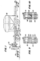
- Fig. 1 Chosen for this purpose is an agricultural implement having a main frame (20) carried on a plurality of ground wheels (22) connected to the frame by crank axles (24) or their equivalent to provide for selective raising and lowering of the frame via hydraulic lift means including one or more two-way motors (26) (Figs. 2-8) typically linked to the crank axles.
- the frame (20) extends forwardly as a draft tongue (28) connected to a tractor drawbar (30) as at (32). Since any type of typical hydraulically equipped farm tractor may be used with the instant environment, details have been omitted and the drawbar (30) will suffice to denote the presence of such tractor.
- the present implement is of the fertilizer distributor type (which is not a limitation) and carries ground working tools (34) supplied from a hopper (36) mounted on the frame.
- ground working tools (34) supplied from a hopper (36) mounted on the frame.
- Factors that affect the height of the implement frame above the ground, and thus the working depth of the tools, are so well known as to require little if anyelabo- ration. Suffice it to say that among these are implement weight, variations in soil conditions, etc. Since accurate tilling, planting, fertilizing, etc., operations depend for success on accurate working depth of the tools, resort has heretofore been had to a variety of devices to sense change in implement height.
- One such sensor is illustrated here at (38) as comprising a smoother that rides the ground rearwardly of the tools and senses variations in implement height relative to a preselected norm below the transport or fully raised position or mode of the implement.
- the sensor is pivoted to the frame (20) at (40) and thus can rise and fall with changes in the terrain.
- the sensor is connected by a link (42) and spring (44) to a bell crank (46) which transmits the movement or signal of the sensor to a novel depth or height control valve designated in its entirety by the numeral (48).
- a novel depth or height control valve designated in its entirety by the numeral (48).
- Fig. 2 Attention is now directed to Fig. 2 for a schematic of the hydraulic motor (26), height control valve (48), a selective control valve (50) and a hydraulic power source (52), customarily integrated with the tractor.
- the power source is shown schematically as including a pump (P) and a reservoir (R) connected to one side of the selective control valve.
- the other side of this valve has fluid pressure lines (54) and (56) leading to the height control valve.
- these lines will be coupled to the tractor hydraulic system by typical couplers, not shown because they are of no detailed significance here.
- the selective,control valve (50) has two active positions, one at each side of a neutral position. The valve is shown in its neutral position in Fig.
- the selective control valve is here shown as being manually controlled, and, in its two active positions, is capable of switching the lines (54) and (56) between pressure and return lines. For example, when the selective control valve is shifted to the right as seen in Fig. 2, an "automatic” condition is achieved and the lines (54) and (56) become respectively pressure and return lines. (The expression “automatic” will be explained subsequently in connection with the functioning of the height control valve (48)).
- the height control valve (48) has four positions labeled “A” (balanced or neutral); “B” (slow raise); “C” (slow lower) and “D” (fast lower/fast raise). That is to say, position “D” is a “dual” position, as will be elaborated later.
- the positions "A”, “B” and “C” are further illustrated respectively in Figs. 4, 5 and 6.
- the two “D” positions appear in Figs. 7 (fast lower) and 8 (fast raise).
- the lines (54) and (56) from the selective control valve (50) lead to the height control valve (48) at ports (58) and (60), and motor ports (62) and (64) at the other side of the valve (48) lead via lines (66) and (68) to opposite ends of the motor (26), here of the two-way piston and cylinder type.
- the height control valve comprises a valve body (70) having a valve spool bore (72) therein in which is axially shiftably carried a valve spool (74).
- the spool projects at opposite ends of the valve bore and at its left-hand end (as seen by the reader) is adted on by the sensor spring and bell crank arrangment (44) and (46).
- the spring alone is shown in F ig. 2 and, in the interests of simplicity, that spring will be regarded as imported into Figs. 4 through 8 to represent biasing means acting on that end portion of the valve spool exposed at the left end of the valve body (70), or in such direction as to cause the spool to move to the right.
- the body At the opposite side of the valve body and at the opposite or right-hand end portion of the valve spool, the body is provided with a chamber (76) which houses a second biasing means in the form of a coiled compression spring (78).
- An outer closure (80) is affixed to the body to complete the enclosure of the spring (78).
- This spring abuts an annular shoulder (82) formed on the valve spool and functions to bias the spool to the left or in opposition to the force of the left-hand spring (44).
- the two biasing means In a selected condition of operation of the implement (implement at a preselected height), the two biasing means will counteract each other and the neutral position of the valve spool will obtain (Fig. 4).
- variations in implement height will effect shifting of the valve spool, depending upon the direction of height change.
- the valve body is formed with internal passage means leading from the pressure and return ports (58) and (60) to the motor ports (62) and (64) via the valve spool bore and the valve spool has lands and grooves for connecting and disconnecting the passage means to accomplish the raise and lower positions outlined heretofore herein.
- the port (58) which acts as the pressure port in the "automatic" phase of the selective control valve (50) (that valve shifted to the right of the neutral position shown in Fig. 2), leads via a valve body passage to the valve bore, at which point the valve spool has a groove (84) between a pair of lands (86) and (88) which, in the Fig.
- the motor (26) is locked against lowering by means of a check valve (96) in a motor line (98) leading to the motor port (62) from the valve spool bore from two branches (100) and (102), but both are blocked off from return to the passage (94) by suitable lands (104) and (106) on the valve spool.
- the check valve (96) opens in response to pressure rise in the line (82) via a branch passage (107), shown her in dotted lines as a schematic representation.
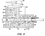
- Fig. 5 shows the shift in the valve spool to the right in response to increase in force as applied by the sensor as the implement tends to lower as respects its selected norm.
- the lowering moves the sensor linke and compresses the sensor spring (44), thus applying the necessary force on the spool.
- the situation acquires a raise of the implement back to the selected norm and, as the spool shifts to the Fig. 5 position, a valve groove (108) between the lands (86) and (104) leads the pressure passage (82) to the branch (102) and thence past the check valve (96) to the motor port and thence to the piston side of the motor (26), extending the motor to raise.
- the rodf side of the piston is returned to reservoir via the line (68), motor port (64) and offset passage (110) to the return passage (94) because of a valve spool groove (112) between a pair of lands (114) and (116).
- Slow raising of the implement is effected here, as desired, by means of a restriction or orifice (118) in the passage (102).
- the schematic showing represents typical screw-in orifices that can be varied as to size to change the raise and lower rate as desired.
- another orifice (120) in a branch passage (122) that is one of a pair including a second branch (124) from the return passage (94) to the valve bore and controlled by the valve lands (104) and (106).
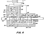
- valve operations so far described have been at a relative slow rate, consistent with responsive implement raising and lowering, so as to avoid sudden and large increments of movement. There are times, however, when faster operation is required or at least desired; e.g., raising and lowering the implement to and from transport position.
- the invention provides a fourth position for the height control valve (48), and this position serves both fast lower and fast raise functions.
- the lowering of the implement at a rapid rate is interrupted as soon as ground contact is made by the sensor, which begins to apply force to the left-hand spring (44), so the descent of the implement ultimately will be at a slower rate,as the spool is compelled to seek its Fig. 6 position.
- the spool occupies the same status as the spool did in the fast lower position, except that the pressure and return passages are reversed.
- pressure is applied to the piston side of the motor free of the restrictions or orifices in the passage means.
- return is free from restrictions (via (68), (64), (110), groove (112), chamber (90), spool groove between the lands (88) and (114) and passage (82) and ultimately to reservoir).
- any suitable means may be provided, several of which are known and need not be described in detail. For example, adjustments may be made in the length of the sensor-to-bell crank linkage (44-46). The pivot of the bell crank may be re-located; or the pivot (40) may be changed. As representative of such means, a handle (130) is provided for manual selection. This could, of course, be replaced with any suitable remote control operative from the tractor.
- valve body (70) has a bore or passage (138) that opens outwardly as a tapped bore (140) and that internally intersects the valve spool bore (74) at the chamber (90).
- a tapped bore (140) opens outwardly as a tapped bore (140) and that internally intersects the valve spool bore (74) at the chamber (90).
- the plug is shown as having a cross bore (142) which registers with the passage (94). Otherwise, the plug blocks off the valve spool bore, resulting in the blockage previously referred to at (92).
- control valve (48) is also different as respects the throttling function at (88-90) and the check valve (136) and hence is designated (48a).
- the other components are alike in both systems and it is felt unnecessary to apply reference numerals to all parts common to both systems.
Landscapes
- Life Sciences & Earth Sciences (AREA)
- Zoology (AREA)
- Engineering & Computer Science (AREA)
- Mechanical Engineering (AREA)
- Soil Sciences (AREA)
- Environmental Sciences (AREA)
- Fluid-Pressure Circuits (AREA)
- Lifting Devices For Agricultural Implements (AREA)
- Multiple-Way Valves (AREA)
Applications Claiming Priority (2)
| Application Number | Priority Date | Filing Date | Title |
|---|---|---|---|
| US06/607,070 US4579038A (en) | 1984-05-04 | 1984-05-04 | Depth control valve and system for agricultural implements |
| US607070 | 1984-05-04 |
Publications (2)
| Publication Number | Publication Date |
|---|---|
| EP0170351A2 true EP0170351A2 (fr) | 1986-02-05 |
| EP0170351A3 EP0170351A3 (fr) | 1986-12-30 |
Family
ID=24430682
Family Applications (1)
| Application Number | Title | Priority Date | Filing Date |
|---|---|---|---|
| EP85303124A Withdrawn EP0170351A3 (fr) | 1984-05-04 | 1985-05-02 | Vanne de réglage de la profondeur de travail pour instrument agricole |
Country Status (7)
| Country | Link |
|---|---|
| US (1) | US4579038A (fr) |
| EP (1) | EP0170351A3 (fr) |
| AU (1) | AU565590B2 (fr) |
| CA (1) | CA1231622A (fr) |
| ES (1) | ES8605932A1 (fr) |
| MX (1) | MX164844B (fr) |
| ZA (1) | ZA853332B (fr) |
Cited By (1)
| Publication number | Priority date | Publication date | Assignee | Title |
|---|---|---|---|---|
| US9826677B2 (en) | 2014-12-16 | 2017-11-28 | Cnh Industrial Canada, Ltd. | Seed implement incorporating a down pressure sensing and adjustment system |
Families Citing this family (10)
| Publication number | Priority date | Publication date | Assignee | Title |
|---|---|---|---|---|
| US4821806A (en) * | 1986-09-05 | 1989-04-18 | Deere & Company | Implement having parallel cylinder depth control and series cylinder lift |
| US5139101A (en) * | 1991-04-10 | 1992-08-18 | Wray-Tech Instruments, Inc. | Hydraulic control system for weighing and two-way valve therefor |
| US5427182A (en) * | 1993-10-08 | 1995-06-27 | Deere & Company | Pressure relieving circuit for a series cylinder depth control |
| US5809862A (en) * | 1995-08-04 | 1998-09-22 | Dallman; Jimmie J. | Flotation control system |
| WO2003087566A1 (fr) * | 2002-04-11 | 2003-10-23 | Siemens Aktiengesellschaft | Systeme d'injection pour moteurs a combustion interne, comprenant une soupape de commande, et soupape de commande d'amenee de carburant dans un systeme d'injection |
| US7316110B2 (en) * | 2005-04-01 | 2008-01-08 | Cnh Canada, Ltd. | Hydraulic system for an air cart |
| US20180319634A1 (en) * | 2014-10-30 | 2018-11-08 | Xuzhou Heavy Machinery Co., Ltd. | Crane hydraulic system and controlling method of the system |
| US10779454B2 (en) | 2018-01-30 | 2020-09-22 | Exmark Manufacturing Company, Incorporated | Soil penetrating apparatus with depth control |
| US10645857B2 (en) | 2018-07-27 | 2020-05-12 | Cnh Industrial America Llc | Implement control system having a manual override |
| CN115380649B (zh) * | 2022-01-11 | 2024-03-22 | 浙江理工大学 | 一种电驱双驱动农机对行横移装置 |
Family Cites Families (6)
| Publication number | Priority date | Publication date | Assignee | Title |
|---|---|---|---|---|
| US2755721A (en) * | 1951-06-22 | 1956-07-24 | Theodore C Rusconi | Automatic depth control systems for agricultural implements |
| US2855752A (en) * | 1955-10-21 | 1958-10-14 | Brusque Rene Le | Hydraulic device for controlling the feed and stop position of a machine element in cutting, sawing and slicing machines |
| US3269464A (en) * | 1963-07-24 | 1966-08-30 | Int Harvester Co | Implement control means for tractor operated agricultural implements |
| US3642027A (en) * | 1970-01-09 | 1972-02-15 | Parker Hannifin Corp | Directional control valve |
| US4044838A (en) * | 1975-04-21 | 1977-08-30 | American Tractor Equipment Corporation | Automatic control for ripper tool |
| DE2943994C2 (de) * | 1979-10-31 | 1981-06-04 | Zahnradfabrik Friedrichshafen Ag, 7990 Friedrichshafen | Hydraulische Hubvorrichtung für Arbeitsgeräte, insbesondere an Schleppen |
-
1984
- 1984-05-04 US US06/607,070 patent/US4579038A/en not_active Expired - Fee Related
-
1985
- 1985-03-27 CA CA000477595A patent/CA1231622A/fr not_active Expired
- 1985-04-29 AU AU41855/85A patent/AU565590B2/en not_active Ceased
- 1985-05-02 EP EP85303124A patent/EP0170351A3/fr not_active Withdrawn
- 1985-05-03 ZA ZA853332A patent/ZA853332B/xx unknown
- 1985-05-03 MX MX205194A patent/MX164844B/es unknown
- 1985-05-03 ES ES542827A patent/ES8605932A1/es not_active Expired
Cited By (1)
| Publication number | Priority date | Publication date | Assignee | Title |
|---|---|---|---|---|
| US9826677B2 (en) | 2014-12-16 | 2017-11-28 | Cnh Industrial Canada, Ltd. | Seed implement incorporating a down pressure sensing and adjustment system |
Also Published As
| Publication number | Publication date |
|---|---|
| ES542827A0 (es) | 1986-04-16 |
| ES8605932A1 (es) | 1986-04-16 |
| CA1231622A (fr) | 1988-01-19 |
| US4579038A (en) | 1986-04-01 |
| EP0170351A3 (fr) | 1986-12-30 |
| ZA853332B (en) | 1987-01-28 |
| AU565590B2 (en) | 1987-09-17 |
| MX164844B (es) | 1992-09-28 |
| AU4185585A (en) | 1985-11-07 |
Similar Documents
| Publication | Publication Date | Title |
|---|---|---|
| US3653446A (en) | Draft and position control for tractor drawn implements | |
| US4821806A (en) | Implement having parallel cylinder depth control and series cylinder lift | |
| US5152347A (en) | Interface system for a towed implement | |
| US4219093A (en) | Vehicle steering assist | |
| US6041583A (en) | Height sensing system for a harvester head | |
| CA2109173C (fr) | Mecanisme de retroaction pour le positionnement d'un instrument | |
| EP0170351A2 (fr) | Vanne de réglage de la profondeur de travail pour instrument agricole | |
| US4311006A (en) | Pressure compensated steering system | |
| US6068063A (en) | Hydraulic connection circuit between first and active hydraulic circuits | |
| US4067394A (en) | Implement with automatic sequencing valve and system | |
| US3771424A (en) | Hydraulic flow amplifier valve | |
| US3990520A (en) | Tractor with hydraulic draft control | |
| CA1045943A (fr) | Detendeur anticavitation et modulateur de pression pour la regulation de cylindres hydrauliques | |
| CA1056262A (fr) | Regulateur hydraulique d'attelage | |
| US2851938A (en) | Tractor hydraulic power lift control | |
| US3731745A (en) | Combined draft hook operating and draft sensing | |
| US3423935A (en) | Hydraulic control system for tractor drawn implement | |
| US2416373A (en) | Joint or separate operation of control valves for two fluid motors | |
| US4434857A (en) | Tractor and implement coupled thereto with hydraulic lift system including phasing valve | |
| US4057109A (en) | Tractor with hydraulic draft control | |
| US2722804A (en) | Tractor hydraulic system with delayed remote cylinder lift and entry | |
| US3834738A (en) | Combined draft hook operating and draft sensing | |
| US3235010A (en) | Load depth control valve | |
| US2670713A (en) | Controllable limit means for regulating strokes of fluid pressure apparatus | |
| US3994347A (en) | Draft control system with control valve |
Legal Events
| Date | Code | Title | Description |
|---|---|---|---|
| PUAI | Public reference made under article 153(3) epc to a published international application that has entered the european phase |
Free format text: ORIGINAL CODE: 0009012 |
|
| AK | Designated contracting states |
Designated state(s): DE FR GB |
|
| PUAL | Search report despatched |
Free format text: ORIGINAL CODE: 0009013 |
|
| AK | Designated contracting states |
Kind code of ref document: A3 Designated state(s): DE FR GB |
|
| STAA | Information on the status of an ep patent application or granted ep patent |
Free format text: STATUS: THE APPLICATION HAS BEEN WITHDRAWN |
|
| 18W | Application withdrawn |
Withdrawal date: 19870805 |
|
| RIN1 | Information on inventor provided before grant (corrected) |
Inventor name: WINTER, DAVID CARL |