EP0170387A1 - Pivot motorisé à grande vitesse avec mécanisme de serrage et de desserrage d'outils - Google Patents
Pivot motorisé à grande vitesse avec mécanisme de serrage et de desserrage d'outils Download PDFInfo
- Publication number
- EP0170387A1 EP0170387A1 EP85304387A EP85304387A EP0170387A1 EP 0170387 A1 EP0170387 A1 EP 0170387A1 EP 85304387 A EP85304387 A EP 85304387A EP 85304387 A EP85304387 A EP 85304387A EP 0170387 A1 EP0170387 A1 EP 0170387A1
- Authority
- EP
- European Patent Office
- Prior art keywords
- tool
- driving shaft
- spindle
- hollow
- housing
- Prior art date
- Legal status (The legal status is an assumption and is not a legal conclusion. Google has not performed a legal analysis and makes no representation as to the accuracy of the status listed.)
- Granted
Links
Images

Classifications
-
- B—PERFORMING OPERATIONS; TRANSPORTING
- B23—MACHINE TOOLS; METAL-WORKING NOT OTHERWISE PROVIDED FOR
- B23B—TURNING; BORING
- B23B31/00—Chucks; Expansion mandrels; Adaptations thereof for remote control
- B23B31/02—Chucks
- B23B31/24—Chucks characterised by features relating primarily to remote control of the gripping means
- B23B31/26—Chucks characterised by features relating primarily to remote control of the gripping means using mechanical transmission through the working-spindle
- B23B31/261—Chucks characterised by features relating primarily to remote control of the gripping means using mechanical transmission through the working-spindle clamping the end of the toolholder shank
- B23B31/263—Chucks characterised by features relating primarily to remote control of the gripping means using mechanical transmission through the working-spindle clamping the end of the toolholder shank by means of balls
-
- B—PERFORMING OPERATIONS; TRANSPORTING
- B23—MACHINE TOOLS; METAL-WORKING NOT OTHERWISE PROVIDED FOR
- B23Q—DETAILS, COMPONENTS, OR ACCESSORIES FOR MACHINE TOOLS, e.g. ARRANGEMENTS FOR COPYING OR CONTROLLING; MACHINE TOOLS IN GENERAL CHARACTERISED BY THE CONSTRUCTION OF PARTICULAR DETAILS OR COMPONENTS; COMBINATIONS OR ASSOCIATIONS OF METAL-WORKING MACHINES, NOT DIRECTED TO A PARTICULAR RESULT
- B23Q5/00—Driving or feeding mechanisms; Control arrangements therefor
- B23Q5/02—Driving main working members
- B23Q5/04—Driving main working members rotary shafts, e.g. working-spindles
- B23Q5/043—Accessories for spindle drives
-
- B—PERFORMING OPERATIONS; TRANSPORTING
- B23—MACHINE TOOLS; METAL-WORKING NOT OTHERWISE PROVIDED FOR
- B23B—TURNING; BORING
- B23B2231/00—Details of chucks, toolholder shanks or tool shanks
- B23B2231/50—Devices to counteract clamping forces exerted within the spindle in order to release the tool or workpiece
-
- Y—GENERAL TAGGING OF NEW TECHNOLOGICAL DEVELOPMENTS; GENERAL TAGGING OF CROSS-SECTIONAL TECHNOLOGIES SPANNING OVER SEVERAL SECTIONS OF THE IPC; TECHNICAL SUBJECTS COVERED BY FORMER USPC CROSS-REFERENCE ART COLLECTIONS [XRACs] AND DIGESTS
- Y10—TECHNICAL SUBJECTS COVERED BY FORMER USPC
- Y10T—TECHNICAL SUBJECTS COVERED BY FORMER US CLASSIFICATION
- Y10T408/00—Cutting by use of rotating axially moving tool
- Y10T408/44—Cutting by use of rotating axially moving tool with means to apply transient, fluent medium to work or product
- Y10T408/45—Cutting by use of rotating axially moving tool with means to apply transient, fluent medium to work or product including Tool with duct
-
- Y—GENERAL TAGGING OF NEW TECHNOLOGICAL DEVELOPMENTS; GENERAL TAGGING OF CROSS-SECTIONAL TECHNOLOGIES SPANNING OVER SEVERAL SECTIONS OF THE IPC; TECHNICAL SUBJECTS COVERED BY FORMER USPC CROSS-REFERENCE ART COLLECTIONS [XRACs] AND DIGESTS
- Y10—TECHNICAL SUBJECTS COVERED BY FORMER USPC
- Y10T—TECHNICAL SUBJECTS COVERED BY FORMER US CLASSIFICATION
- Y10T408/00—Cutting by use of rotating axially moving tool
- Y10T408/94—Tool-support
- Y10T408/95—Tool-support with tool-retaining means
- Y10T408/957—Tool adapter
-
- Y—GENERAL TAGGING OF NEW TECHNOLOGICAL DEVELOPMENTS; GENERAL TAGGING OF CROSS-SECTIONAL TECHNOLOGIES SPANNING OVER SEVERAL SECTIONS OF THE IPC; TECHNICAL SUBJECTS COVERED BY FORMER USPC CROSS-REFERENCE ART COLLECTIONS [XRACs] AND DIGESTS
- Y10—TECHNICAL SUBJECTS COVERED BY FORMER USPC
- Y10T—TECHNICAL SUBJECTS COVERED BY FORMER US CLASSIFICATION
- Y10T409/00—Gear cutting, milling, or planing
- Y10T409/30—Milling
- Y10T409/309352—Cutter spindle or spindle support
- Y10T409/309408—Cutter spindle or spindle support with cutter holder
- Y10T409/309464—Cutter spindle or spindle support with cutter holder and draw bar
-
- Y—GENERAL TAGGING OF NEW TECHNOLOGICAL DEVELOPMENTS; GENERAL TAGGING OF CROSS-SECTIONAL TECHNOLOGIES SPANNING OVER SEVERAL SECTIONS OF THE IPC; TECHNICAL SUBJECTS COVERED BY FORMER USPC CROSS-REFERENCE ART COLLECTIONS [XRACs] AND DIGESTS
- Y10—TECHNICAL SUBJECTS COVERED BY FORMER USPC
- Y10T—TECHNICAL SUBJECTS COVERED BY FORMER US CLASSIFICATION
- Y10T483/00—Tool changing
- Y10T483/17—Tool changing including machine tool or component
- Y10T483/1733—Rotary spindle machine tool [e.g., milling machine, boring, machine, grinding machine, etc.]
- Y10T483/1736—Tool having specific mounting or work treating feature
Definitions
- the present invention relates to spindles for material cutting operations and, in particular, high speed spindles having a self-contained clamping/unclamping mechanism to facilitate tool changing and to tool clamping/unclamping methods.
- High speed motorized spindles were initially developed for precision grinding and over the years have been used for other machining operations involving heavy stock removal such as rotary milling, end milling and end facing. Such high speed spindles have been used in conjunction with machining centers having multiple tool storage and tool changer mechanisms for exchanging one type of tool for another on the prime spindle of the machining center.
- U.S. Patent 3,803,981 issued April 16, 1974 to Allgeyer illustrates a sub-spindle mounted in a prime spindle.
- U.S. Patent 4,077,736 describes an electric motor driven drill in the toolholder of a machine tool.
- the present invention contemplates a spindle having a tool clamping means slidably disposed in a hollow tool-driving shaft slidable in one direction to release a tool shank and in the other direction to grip the tool shank and actuating means in the housing for slidably actuating the tool clamping means.
- the actuating means includes piston means slidably disposed in the housing for engaging and sliding the tool clamping means in the tool-driving shaft.
- the spindle includes means operable in response to movement of the piston means relative to the tool-clamping means for releasably clamping the tool-driving shaft against movement.
- the spindle also preferably includes means to lock the rotary position of the tool-driving shaft when the tool-clamping means is released to thereby facilitate tool exchange.
- the spindle includes spring means in the hollow tool-driving shaft biasing the drawbar member of the tool clamping means in a direction to cause multiple fingers on a tool clamping collet connected to the working end of the drawbar member to be cammed to grip the tool shank.
- the piston means includes a piston rod extending into the rear non-working end of the tool-driving shaft engageable end-to-end with the drawbar member when the piston is slid in the other direction to cause the collet fingers to open or release the tool shank.
- the shaft clamping collet extends out of the tool-driving shaft and is mounted to a cylinder member which slidably receives the piston means and is itself slidable in the housing to cause the collet fingers to be in clamping or gripping engagement in the groove of the tool-driving shaft.
- the cylinder member is preferably spring biased to center the collet fingers relative to the groove of the tool-driving shaft when the latter is unclamped.
- the shaft clamping collet fingers are released from the shaft groove when the piston means is slid in the direction to allow the spring means to bias or slide the drawbar member in the tool gripping direction.
- the piston rod preferably carries a sensed member, the movement of which is sensed by a position sensor in the housing so that the position of the piston means between the tool release position and tool gripped position is known.
- the hollow tool-driving shaft also includes in a preferred embodiment a cam means thereon and rotatable therewith for operative engagement by cam lock means movably mounted in the housing to thereby lock the shaft rotary position during tool exchange.
- the cam means may include cne or more sensed members for sensing by a position sensor in the housing so that the rotary position of the shaft and tool-shank engaging flanges on the working end thereof are known for correct tool exchange.
- the spindle housing preferably includes a shank on one end thereof adapted to be received in the prime spindle of a machining center or machine tool. The working embodiment of the invention is especially useful in conjunction with a machining center as a result of the features described hereinabove.
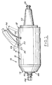
- Fig. 1 illustrates a high speed motorized spindle 10 of the invention.
- the spindle includes a housing 12 comprised of a forward housing section 14, intermediate housing section 16 and rear housing section 18 fastened together by suitable means such as machine screws 20 illustrated for forward housing section 14 in Fig. 2.
- Attached to the housing are various connectors for coolant, lubrication and electrical power, and sensors used in the spindle.
- oil mist inlet 22 and oil mist supply conduit 24 are provided for internal shaft bearings to be described.
- a coolant inlet 23 and coolant supply conduit 28 are provided for motor cooling.
- An electrical power cable is attached at 30 to the housing to supply motor current.
- Proximity sensor lead lines 32,34 are provided and connected to sensors described below.
- a hollow tool-driving shaft 70 Protruding through the forward housing section 14 is the forward or working end 40 of a hollow tool-driving shaft 70.
- a tool shank is clamped in the hollow shaft 70 as will be described in more detail hereinbelow.
- a bearing retainer nut 46 is also visible on the forward end of the spindle and is fastened by threads to the shaft 70 as shown shown in Fig. 3.
- the rear end of the spindle 10 has a tapered shank 52 with an annular flange 54 attached to the rear housing section 18 as by machine screws (not shown) or other suitable means.
- the shank 52 is tapered so as to be receivable in a prime spindle (not shown) of known machining centers or machine tools.
- the shank terminates in a knob 56 threaded thereinto (Fig. 3) and adapted to be gripped by fingers of a clamping collet in the prime spindle in well known fashion.
- the spindle 10 is thus mountable in the prime spindle of a machining center or machine tool and the power, lubrication, coolant and control sensors can be connected to respective sources or control units external of the spindle.
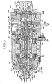
- Figs. 3 and 4 illustrate the internal features of the spindle 10.
- the intermediate housing section 16 includes a central large diameter bore 60 and an annular coolant passage 62.
- Coolant passage 62 receives coolant such as corrosion inhibited water from coolant supply conduit 28 for circulation around motor 64 for eventual discharge through a coolant discharge conduit (not shown) attached to the housing.
- coolant is supplied from a coolant source (not shown) located exteriorly of the spindle 10.
- Received in the central bore 60 is a reversible electric motor 64 of the high frequency alternating current induction type which is cooled by circulating coolant confined in passage 62 out of contact of the motor and which receives electrical power via leads 63 extending from power cable 30.
- the motor speed and direction of rotation are controlled by a commercially available solid state variable frequency power supply 31 available from Volkman Corp. or other known sources.
- the motor typically includes a stator winding 66 supported (press fit) into bore 60 and a rotor winding 68 carried and affixed on rotatable hollow tool-driving shaft 70.
- the left-hand end or forward end of the tool-driving shaft is journaled in a pair of forward anti-friction bearings 74 each comprising an inner race 76, outer race 78 and balls 80 therebetween, in particular being journaled in inner races 76 thereof.
- the outer races 78 are supported in a cylindrical bore 82 in the forward housing section 14.
- an oil-mist nozzle 84 Positioned between the bearings 74 is an oil-mist nozzle 84 having apertures 86 for providing a bearing mist from oil mist supply passage 90 connected to an external oil mist source (not shown) by means of longitudinal or axial passage 92.
- a high speed bearing arrangement having oil mist supplied from a blender-distributor unit or source is described in the Mitchell and Thayer U.S. Patent 3,939,744 of common assignee herewith, the teachings of which are incorporated herein by reference.
- the bearings 74 are held between an inner collar 96 and outer collar 46 on the forward housing section 14 as shown.
- the right-hand end or rear end of tool-driving shaft 70 is similarly journaled in a pair of anti-friction bearings 102 similar to those described above.
- Oil mist is provided by a nozzle 104 identical to that (84) described above for the forward bearings from a passage 106 connected to axial passage 92.
- the outer races 108 of the rear bearings are supported against a tubular rear bearing cage member 110 which in turn is supported in small diameter bore 112 in the intermediate housing section.
- rear bearings 102 are held between the radial flange 114 of the rear bearing cage member and a collar 116 threaded exteriorly onto the end of the tool-driving shaft 70.
- Shaft bearings 74 and 102 are subjected an initial selected preload in the axial direction toward the right in Fig. 3 by means of multiple spacings 139 (only one shown) engaging a collar 141 attached such as by machine screws to rear bearing cage member 110 as shown.
- the tool-driving shaft 70 is hollow and includes a longitudinal or axial bore 120 therethrough.
- the forward end of the bore 120 receives a shank-receiving sleeve 122 having a circumferential groove 124 with cam surfaces 126 and a tapered surface 128.
- a tool shank 130 is shown received in sleeve 122.
- the tapered tool shank 132 is received against taper sleeve surfaces 128.
- the tool shank 130 also includes an exterior cap 134 having a pair of diametrically opposed arcuate slots 136 which are spaced apart on opposite sides of the cap and are adapted to receive arcuate flanges 138 formed on the forward end of the tool-driving shaft 70.
- Flanges 138 and slots 136 are used during tool exchange to ensure proper positioning and orientation of the tool shank and tool-driving shaft relative to one another.
- the tool shank 130 includes a central axial bore 140 for purposes to be described and also a retention knob 142 adapted to be gripped by multiple fingers 144 of the collet 146 disposed in the bore 120 of the tool-driving shaft 70.
- the collet is connected to a drawbar member 148 by a long machine screw 150 and sleeve 152.
- an elongated stop member 154 is disposed therein and includes a rear end 156 adapted to function, if necessary, as a stop against the end of machine screw 150.
- the stop member 154 also includes an enlarged cam portion toward the forward portion thereof supporting spring biased balls 160 (only one shown) which engage in an annular groove 162 in tool shank receiving sleeve 122. Ball engagement in groove 162 provides an initial locking action to initially hold the tool shank 130 in the forward end of the tool-driving shaft 70.
- the tool shank clamping collet 146 is attached to drawbar member 148 and is slidable therewith in central bore 120 of the tool-driving shaft.
- the drawbar member is biased or urged to the right (in Fig. 3) by a plurality of annular spring washers 170 positioned around the drawbar member as shown and held together by retainer collar 172 threaded onto the threaded rear end of the drawbar member.
- a piston rod 174 Extending into the rear open end of the tool-driving shaft 70 is a piston rod 174 which includes cam surface 175 near the forward end thereof as shown for purposes to be explained below.
- the piston rod extends from a double-acting piston member 178 slidably received in cylinder insert 180 in the rear housing section 18.
- the insert 180 is closed at its rearward end by an insert cap or cover 182 fastened such as by machine screws (not shown) to the cylinder insert 180. Cylinder insert 180 and attached cover 182 together are slidably received in the bore 18a of housing section 18 as shown for purposes to be explained below.
- the piston member includes an O-ring seal to hydraulically separate the forward side 184 and the rearward side 186.
- Appropriate oil seals 188 are shown between the insert 180 and insert cap 182 and the rear housing section 18 for oil sealing purposes. Seals 188 prevent oil leakage between cylinder insert 180 and housing section 18, especially as the cylinder insert slides therein.
- the piston member forms a forward chamber 190 and a rear chamber 192 in insert 180 and each chamber communicates with its own respective oil supply passage 194,196 receiving fluid pressure from appropriate external sources (not shown).
- the piston member 178 is actuated to slide left (forward) or right (rearward) in Fig. 3 by increasing oil pressure on one side or the other of the piston member. For example, to slide the piston member forward, oil pressure in rear chamber 192 is increased and vice versa. Movement of the piston member of course causes sliding movement of the piston rod 174 relative to the tool-driving shaft 70.
- the piston rod is slid forward or left in Fig. 3 to engage the rear end of the drawbar member in end-to-end relation and push the drawbar member in a syringe type action in bore 120 to the left until the collet fingers 144 can expand past cam surfaces 126 of circumferential groove 124 in the shank-receiving sleeve 122 at the forward end of the tool-driving shaft 70.
- the tool shank 130 can then be withdrawn from the sleeve 122 by a suitable tool changer (not shown) compressing locking ball 160.
- the cam surface 175 thereon engages complementary cam surfaces 281 on multiple fingers 282 of collet 284 for clamping the shaft 70 against movement in the bore 120.
- Bore 120 includes a circumferential groove 286 positioned to receive the ends of fingers 282 in locking engagement when they are expanded by the camming action of the piston rod 174.
- the shaft clamping collet 284 is fastened at its rear end to slidable cylinder insert 180, in particular to a cylindrical forwardly projecting extension 180a thereof by machine screws (not shown) or other suitable means.Clamping of the shaft 70 in this manner during sliding movement of the piston rod and thus the drawbar member is highly important to minimize axial tool unclamping forces exerted on the anti-friction bearings 74,102, which are expensive precision bearings to accommodate shaft speeds of typically 15000 to 30000 r.p.m.
- piston member 178 is slid rearwardly or to the left in Fig. 3 by pressurizing front chamber 190.
- the spring washers 170 urge the drawbar member 148 and tool clamping collet 146 to the right and cause collet fingers 144 to be cammed against the tool shank retention knob 142 by camming engagement between cam surfaces 126 and end cam surfaces 145 on the collet finger 144 to grip the retention knob as shown in Fig. 3.
- the piston rod 174 carries and has attached thereto a pin member 190 for movement with the piston rod outside the hollow tool-driving shaft 70 relative to a position proximity sensor 192 mounted in the rear housing section 18, and connected to suitable position indicating display circuitry.
- the pin member 190 slides in a space between the collet fingers 282 between the rear position shown in Fig. 3 adjacent sensor 192 forwardly to the position shown in phantom lines. The rear position is sensed and displayed as the "tool clamped" position and the forward position (phantom lines) is sensed as the "tool unclamped" position.
- the forward end of the hollow tool-driving shaft 70 includes opposite disposed circumferentially spaced apart flanges 138 and these flanges are received in corresponding slots 136 in the cap 134 of the tool shank 130 to insure proper alignment therebetween.
- a rotary shaft locking mechanism is provided to insure the flanges - 138 are properly positioned relative to the incoming tool shank and locked against movement during tool exchange.
- This shaft locking mechanism includes a cam plate 200 mounted on and rotatable with shaft 70.
- the cam plate includes a pair of oppositely disposed ramps 202 each terminating in a radial shoulder 204.
- a position proximity sensor 208 is positioned in the rear housing section 18 adjacent the cam plate on the rear facing side thereof to sense the location of the sensed members 206.
- the flanges 138 are in the proper orientation to engage in slots 136 in the tool shank caps 134.
- a lock solenoid 210 mounted in a passage 212 in the rear housing section is actuated. Solenoid 210 includes plunger 214 slidably connected to cam lock member 216 by pin 218 in slot 219.
- Cam lock member 216 is also pivotally connected to the rear housing section 18 by pin 220 as shown in Fig. 4. Movement of the solenoid plunger 214 outward (toward the bottom of Fig. 4) will cause cam lock member 216 to be pivoted toward shaft 70 to bring cam nose 216a against radial shoulder 204 on the cam plate. At this time, motor rotation or torque on shaft 70 is reversed and maintained to keep the nose 216a and shoulder 204 clamped together. Motor reversal is effected by means of the aforementioned commercially available solid state variable frequency power supply 31. This cam locking action assures the tool-driving shaft 70 and forward flanges 138 are locked in proper orientation to be received in cap slots 134.
- Operation of the spindle described begins by locking the tool-driving shaft 70 with flanges 138 in proper orientation. Sensor 208 assures that the shaft is so locked. Then, piston member 178 is slidably actuated to the left in Fig. 3 by pressurizing rear chamber 192 to push the drawbar member 148 and tool clamping collet 146 to the forward position where collet fingers 144 expand radially outward into sleeve groove 122. Sensor 192 senses the "unclamp position" and a tool changer (not shown) can remove the tool shank and replace it with another tool shank.
- the piston member is urged to the right in Fig. 3 to withdraw piston rod 174 and at the same time spring washers 170 urge the drawbar member and attached tool clamping collet to the right to cause the collet fingers 144 to be cammed in gripping engagement on the retention knob 142 of the tool shank 130.
- Sensor 192 senses the clamped position and effects de-activation of the solenoid 210 to withdraw its plunger 214 and release cam lock member 216 from radial shoulder 204 of cam plate 200 and also releases reverse motor torque to free the tool-driving shaft 70 for rotation in the other direction to effect machining.
Landscapes
- Engineering & Computer Science (AREA)
- Mechanical Engineering (AREA)
- Gripping On Spindles (AREA)
- Automatic Tool Replacement In Machine Tools (AREA)
- Jigs For Machine Tools (AREA)
- Turning (AREA)
Applications Claiming Priority (2)
| Application Number | Priority Date | Filing Date | Title |
|---|---|---|---|
| US06/627,323 US4583894A (en) | 1984-07-02 | 1984-07-02 | High speed motorized spindle with tool clamping/unclamping mechanism |
| US627323 | 1990-12-14 |
Publications (2)
| Publication Number | Publication Date |
|---|---|
| EP0170387A1 true EP0170387A1 (fr) | 1986-02-05 |
| EP0170387B1 EP0170387B1 (fr) | 1988-08-10 |
Family
ID=24514194
Family Applications (1)
| Application Number | Title | Priority Date | Filing Date |
|---|---|---|---|
| EP85304387A Expired EP0170387B1 (fr) | 1984-07-02 | 1985-06-19 | Pivot motorisé à grande vitesse avec mécanisme de serrage et de desserrage d'outils |
Country Status (6)
| Country | Link |
|---|---|
| US (1) | US4583894A (fr) |
| EP (1) | EP0170387B1 (fr) |
| JP (1) | JPS6165704A (fr) |
| CH (1) | CH667415A5 (fr) |
| DE (1) | DE3564208D1 (fr) |
| SE (1) | SE462205B (fr) |
Cited By (5)
| Publication number | Priority date | Publication date | Assignee | Title |
|---|---|---|---|---|
| DE3533623A1 (de) * | 1985-09-20 | 1987-04-16 | Ott Gmbh A | Steuerantrieb fuer eine steuerstange in einer rotierenden maschinenspindel |
| FR2649921A1 (fr) * | 1989-07-18 | 1991-01-25 | Almac Sa | Broche de machine-outil |
| EP0552982A1 (fr) * | 1992-01-22 | 1993-07-28 | The Ingersoll Milling Machine Company | Broche à grande vitesse et entraînement |
| EP0827796A1 (fr) * | 1996-09-10 | 1998-03-11 | Röhm GmbH | Dispositif de découplement |
| US11415123B2 (en) | 2016-10-19 | 2022-08-16 | Halliburton Energy Services. Inc. | Controlled stop for a pump |
Families Citing this family (25)
| Publication number | Priority date | Publication date | Assignee | Title |
|---|---|---|---|---|
| US4836723A (en) * | 1985-10-08 | 1989-06-06 | Flammini John T | Spindle assembly |
| DE3617103C1 (de) * | 1986-05-21 | 1987-08-27 | Fortuna Werke Maschf Ag | Mit einer Werkzeugspanneinrichtung versehene Spindel einer Werkzeugmaschine |
| DE3714562A1 (de) * | 1987-04-30 | 1988-11-10 | Deckel Ag Friedrich | Werkzeugspindelanordnung mit einem elektrischen antriebsmotor |
| JPH0683941B2 (ja) * | 1988-04-15 | 1994-10-26 | 株式会社森精機製作所 | 工作機械の自動工具交換装置 |
| JPH0398716A (ja) * | 1989-09-09 | 1991-04-24 | Brother Ind Ltd | 工作機械 |
| DE4431149C2 (de) * | 1994-09-01 | 1997-04-17 | Mapal Fab Praezision | Werkzeug mit zwei ineinanderliegenden Teilwerkzeugen |
| JPH08174358A (ja) * | 1994-12-26 | 1996-07-09 | Fanuc Ltd | 工作機械のサブモータユニット装着装置 |
| DE19509524C2 (de) * | 1995-03-20 | 1999-01-14 | Mapal Fab Praezision | Spanendes Werkzeug zur Bohrungsfeinbearbeitung |
| JPH1015766A (ja) * | 1996-06-28 | 1998-01-20 | Toshiba Mach Co Ltd | アタッチメント自動交換装置 |
| SE512241C2 (sv) * | 1998-06-24 | 2000-02-14 | Sandvik Ab | Hållare för lösgörbar montering av skärverktyg |
| SE9901052L (sv) * | 1999-03-23 | 2000-02-28 | Lind Finance & Dev Ab | Anordning vid verktygsspindel |
| SE512312C2 (sv) * | 1999-03-23 | 2000-02-28 | Lind Finance & Dev Ab | Anordning vid verktygsspindel |
| JP2000354989A (ja) * | 1999-06-16 | 2000-12-26 | Fanuc Ltd | 自動刃具交換装置 |
| IT1309309B1 (it) * | 1999-06-30 | 2002-01-22 | Hsd Srl | Elettromandrino. |
| IT1314043B1 (it) * | 1999-10-14 | 2002-12-03 | F M Elettromeccanica S R L | Testa per macchina utensile. |
| ITBA20010022A1 (it) * | 2001-05-11 | 2002-11-11 | Jupiter Srl | Testa di precisione ad assi controllati con cambio automatico degli elettromandrini |
| DE10316244B3 (de) * | 2003-04-09 | 2004-07-29 | Siemens Ag | Bearbeitungsspindel mit Ausstoßfunktion |
| US7704022B2 (en) * | 2003-05-02 | 2010-04-27 | Mircea Petrescu | Motorized precision spindle apparatus |
| EP1736265B1 (fr) * | 2005-06-21 | 2007-09-05 | Paul Müller GmbH & Co. KG Unternehmensbeteiligungen | Broche pourvue d'une douille de serrage et d'une unité d'embrayage |
| ES2332815T3 (es) * | 2006-12-29 | 2010-02-12 | Vigel S.P.A. | Metodo y sistema de monitorizacion para un arbol portaherramientas. |
| DK2881200T3 (en) * | 2013-12-04 | 2019-04-23 | Gildemeister Drehmaschinen Gmbh | Spindle unit for turning and milling machines |
| CN112676587A (zh) * | 2020-12-25 | 2021-04-20 | 深圳市恒兴隆机电有限公司 | 一种精密高速自动换刀电主轴 |
| CN116652657A (zh) * | 2023-06-21 | 2023-08-29 | 珠海格力电器股份有限公司 | 一种中心出水的打刀结构和机床 |
| CN116871543B (zh) * | 2023-07-17 | 2025-10-03 | 安徽台信科技有限公司 | 一种大扭矩带有锁紧装置的内藏式主轴 |
| CN117483822B (zh) * | 2023-12-05 | 2026-02-06 | 珠海格力电器股份有限公司 | 一种电主轴和机床 |
Citations (3)
| Publication number | Priority date | Publication date | Assignee | Title |
|---|---|---|---|---|
| DE2711238A1 (de) * | 1977-03-15 | 1978-09-28 | Meidensha Electric Mfg Co Ltd | Motorfraesvorrichtung |
| US4196501A (en) * | 1977-04-25 | 1980-04-08 | Fujitsu Fanuc Limited | Machine tool |
| EP0044886A1 (fr) * | 1980-07-25 | 1982-02-03 | Toyoda Koki Kabushiki Kaisha | Machine-outil à fonction de changement d'outil automatique |
Family Cites Families (6)
| Publication number | Priority date | Publication date | Assignee | Title |
|---|---|---|---|---|
| DE2450323C3 (de) * | 1974-10-23 | 1978-12-21 | Friedrich Deckel Ag, 8000 Muenchen | Werkzeugspannvorrichtung |
| US4026191A (en) * | 1975-11-17 | 1977-05-31 | Sundstrand Corporation | Machine tool |
| US4068559A (en) * | 1976-07-30 | 1978-01-17 | Schmid Jr Herbert | Tool fastening device |
| DE2758858C2 (de) * | 1977-02-09 | 1985-07-11 | Ex-Cell-O Corp., Troy, Mich. | Werkzeugmaschine |
| US4303360A (en) * | 1980-02-29 | 1981-12-01 | Giddings & Lewis, Inc. | Power drawfinger system for machine tool spindle |
| JPS5789542A (en) * | 1980-11-21 | 1982-06-03 | Toyoda Mach Works Ltd | Automatic tool replacing apparatus |
-
1984
- 1984-07-02 US US06/627,323 patent/US4583894A/en not_active Expired - Fee Related
-
1985
- 1985-06-19 EP EP85304387A patent/EP0170387B1/fr not_active Expired
- 1985-06-19 DE DE8585304387T patent/DE3564208D1/de not_active Expired
- 1985-06-26 CH CH2717/85A patent/CH667415A5/de not_active IP Right Cessation
- 1985-06-26 SE SE8503193A patent/SE462205B/sv not_active IP Right Cessation
- 1985-07-01 JP JP60142669A patent/JPS6165704A/ja active Pending
Patent Citations (3)
| Publication number | Priority date | Publication date | Assignee | Title |
|---|---|---|---|---|
| DE2711238A1 (de) * | 1977-03-15 | 1978-09-28 | Meidensha Electric Mfg Co Ltd | Motorfraesvorrichtung |
| US4196501A (en) * | 1977-04-25 | 1980-04-08 | Fujitsu Fanuc Limited | Machine tool |
| EP0044886A1 (fr) * | 1980-07-25 | 1982-02-03 | Toyoda Koki Kabushiki Kaisha | Machine-outil à fonction de changement d'outil automatique |
Cited By (5)
| Publication number | Priority date | Publication date | Assignee | Title |
|---|---|---|---|---|
| DE3533623A1 (de) * | 1985-09-20 | 1987-04-16 | Ott Gmbh A | Steuerantrieb fuer eine steuerstange in einer rotierenden maschinenspindel |
| FR2649921A1 (fr) * | 1989-07-18 | 1991-01-25 | Almac Sa | Broche de machine-outil |
| EP0552982A1 (fr) * | 1992-01-22 | 1993-07-28 | The Ingersoll Milling Machine Company | Broche à grande vitesse et entraînement |
| EP0827796A1 (fr) * | 1996-09-10 | 1998-03-11 | Röhm GmbH | Dispositif de découplement |
| US11415123B2 (en) | 2016-10-19 | 2022-08-16 | Halliburton Energy Services. Inc. | Controlled stop for a pump |
Also Published As
| Publication number | Publication date |
|---|---|
| JPS6165704A (ja) | 1986-04-04 |
| SE462205B (sv) | 1990-05-21 |
| EP0170387B1 (fr) | 1988-08-10 |
| SE8503193D0 (sv) | 1985-06-26 |
| CH667415A5 (de) | 1988-10-14 |
| US4583894A (en) | 1986-04-22 |
| SE8503193L (sv) | 1986-01-03 |
| DE3564208D1 (en) | 1988-09-15 |
Similar Documents
| Publication | Publication Date | Title |
|---|---|---|
| US4583894A (en) | High speed motorized spindle with tool clamping/unclamping mechanism | |
| EP0552982B1 (fr) | Broche à grande vitesse et entraínement | |
| US4122755A (en) | Self-locking chuck | |
| US3795957A (en) | Apparatus for boring and burnishing internal cylindrical surfaces of metallic workpieces | |
| US3979819A (en) | Machine tool with a turret head for multiple spindle units and automatic tool changing apparatus | |
| US4131054A (en) | High speed spindle and draw bar assembly | |
| MX2011006311A (es) | Ensamble de herramienta automatica. | |
| KR101999330B1 (ko) | 공작기계의 빌트인 타입 전기 구동 시스템 및 그 작동방법 | |
| CA1082904A (fr) | Mandrin a serrage automatique | |
| EP0651686B1 (fr) | Broche et porte-outil pour machine-outil | |
| US3374711A (en) | Power drawbar | |
| US4726717A (en) | Deep-bore drilling machine | |
| US4692074A (en) | Tool coupling arrangement for a tooling assembly | |
| WO1994002283B1 (fr) | Broche et porte-outil pour machine-outil | |
| US4175898A (en) | Tool changing apparatus | |
| US4148246A (en) | High speed spindle and draw bar assembly | |
| US4777714A (en) | Quick-change mount for chucks | |
| US4856153A (en) | Spindle mechanism | |
| US5544556A (en) | Reversibly rotatable chuck with internal cam for shifting work axis | |
| US4715102A (en) | Machine tool | |
| US3672691A (en) | Means for operating releasable tool chucks | |
| EP0095240A2 (fr) | Porte-outils | |
| US4787134A (en) | Automatic tool exchange apparatus | |
| GB2061159A (en) | Work holding device for the turret of a turret lathe | |
| US3541903A (en) | Screw machine chuck |
Legal Events
| Date | Code | Title | Description |
|---|---|---|---|
| PUAI | Public reference made under article 153(3) epc to a published international application that has entered the european phase |
Free format text: ORIGINAL CODE: 0009012 |
|
| AK | Designated contracting states |
Designated state(s): DE FR GB IT |
|
| 17P | Request for examination filed |
Effective date: 19860307 |
|
| 17Q | First examination report despatched |
Effective date: 19870518 |
|
| GRAA | (expected) grant |
Free format text: ORIGINAL CODE: 0009210 |
|
| AK | Designated contracting states |
Kind code of ref document: B1 Designated state(s): DE FR GB IT |
|
| ITF | It: translation for a ep patent filed | ||
| REF | Corresponds to: |
Ref document number: 3564208 Country of ref document: DE Date of ref document: 19880915 |
|
| EN | Fr: translation not filed | ||
| PLBE | No opposition filed within time limit |
Free format text: ORIGINAL CODE: 0009261 |
|
| STAA | Information on the status of an ep patent application or granted ep patent |
Free format text: STATUS: NO OPPOSITION FILED WITHIN TIME LIMIT |
|
| 26N | No opposition filed | ||
| PGFP | Annual fee paid to national office [announced via postgrant information from national office to epo] |
Ref country code: GB Payment date: 19920604 Year of fee payment: 8 |
|
| PGFP | Annual fee paid to national office [announced via postgrant information from national office to epo] |
Ref country code: FR Payment date: 19920619 Year of fee payment: 8 |
|
| ITTA | It: last paid annual fee | ||
| PGFP | Annual fee paid to national office [announced via postgrant information from national office to epo] |
Ref country code: DE Payment date: 19930518 Year of fee payment: 9 |
|
| PG25 | Lapsed in a contracting state [announced via postgrant information from national office to epo] |
Ref country code: GB Effective date: 19930619 |
|
| GBPC | Gb: european patent ceased through non-payment of renewal fee |
Effective date: 19930619 |
|
| PG25 | Lapsed in a contracting state [announced via postgrant information from national office to epo] |
Ref country code: FR Effective date: 19940228 |
|
| REG | Reference to a national code |
Ref country code: FR Ref legal event code: ST |
|
| PG25 | Lapsed in a contracting state [announced via postgrant information from national office to epo] |
Ref country code: DE Effective date: 19950301 |