EP0170455A2 - Bloc modulaire et systèmes électriques de construction utilisant celui-ci - Google Patents
Bloc modulaire et systèmes électriques de construction utilisant celui-ci Download PDFInfo
- Publication number
- EP0170455A2 EP0170455A2 EP85304954A EP85304954A EP0170455A2 EP 0170455 A2 EP0170455 A2 EP 0170455A2 EP 85304954 A EP85304954 A EP 85304954A EP 85304954 A EP85304954 A EP 85304954A EP 0170455 A2 EP0170455 A2 EP 0170455A2
- Authority
- EP
- European Patent Office
- Prior art keywords
- block
- locking elements
- wedge
- modular block
- blocks
- Prior art date
- Legal status (The legal status is an assumption and is not a legal conclusion. Google has not performed a legal analysis and makes no representation as to the accuracy of the status listed.)
- Granted
Links
- 230000000712 assembly Effects 0.000 title description 3
- 238000000429 assembly Methods 0.000 title description 3
- 238000003780 insertion Methods 0.000 claims description 11
- 230000037431 insertion Effects 0.000 claims description 11
- 230000013011 mating Effects 0.000 claims description 9
- 238000010276 construction Methods 0.000 abstract description 3
- 230000000295 complement effect Effects 0.000 abstract 1
- 238000004519 manufacturing process Methods 0.000 description 3
- 238000000034 method Methods 0.000 description 3
- 241001417501 Lobotidae Species 0.000 description 1
- 238000013459 approach Methods 0.000 description 1
- 230000027455 binding Effects 0.000 description 1
- 230000000694 effects Effects 0.000 description 1
- 238000007567 mass-production technique Methods 0.000 description 1
- 238000000465 moulding Methods 0.000 description 1
- 229920003023 plastic Polymers 0.000 description 1
- 239000004033 plastic Substances 0.000 description 1
- 230000000717 retained effect Effects 0.000 description 1
- 230000002441 reversible effect Effects 0.000 description 1
Images



Classifications
-
- H—ELECTRICITY
- H01—ELECTRIC ELEMENTS
- H01R—ELECTRICALLY-CONDUCTIVE CONNECTIONS; STRUCTURAL ASSOCIATIONS OF A PLURALITY OF MUTUALLY-INSULATED ELECTRICAL CONNECTING ELEMENTS; COUPLING DEVICES; CURRENT COLLECTORS
- H01R13/00—Details of coupling devices of the kinds covered by groups H01R12/70 or H01R24/00 - H01R33/00
- H01R13/46—Bases; Cases
- H01R13/514—Bases; Cases composed as a modular blocks or assembly, i.e. composed of co-operating parts provided with contact members or holding contact members between them
Definitions
- This invention relates broadly to modular blocks and to assemblies employing same; it is particularly useful in enabling the easy customized fabrication of electrical interface boards of the type in which electrical connectors are mounted on the board to enable easy interconnection between electrical elements.
- a customized interface board may, for example, be mounted on the firewall under the hood of an automotive truck; in a typical case, wires or cables, terminated in appropriate connectors, lead to the rear side of the board, the connectors being mounted within corresponding openings inside the various modular blocks.
- the front of the board will typically have plugged into it various electrical components, for example flashers, relays, or connectors on the ends of other wires, the terminals of these electrical elements typically being plugged into suitable standard openings provided on the front face of the interface board.
- Another object is to provide such modular blocks, structures and interface boards which are inexpensive to manufacture, easy to assemble, yet capable of a large variety of customized configurations.
- a further object is to provide a new and useful locking system for enabling the easy manual assembly of such blocks to other blocks or structures.
- a modular block having at least one side face provided with at least one set of integral locking elements; all side faces of the modular block are preferably provided with identical sets of such integral locking elements.
- Each such set of locking elements comprises at least one bar-like land and one corresponding groove of a size snugly to receive such a land, so that the lands and grooves of another such modular block or structure will be alignable and matable with the lands and grooves of the first said modular block, thereby to lock two so-assembled blocks against sideways motion normal to the direction of the bars and grooves.
- the set of locking elements also comprises at least first and second abutment ⁇ means symmetrically positioned on said one face of the modular block so as to mate with corresponding abutment means on other similar modular blocks or structures, whereby when a modular block is placed in mating engagement with another modular block or structure, these abutment means prevent relative motion of the blocks or structures with respect to each other along the direction of the lands and grooves.
- each such side surface of the modular block is provided with a dovetail mortise, symmetrically disposed with respect to the centerline of the set of locking elements, so that when two such sets of locking elements are placed in confronting relationship the two mortises will be in aligned confronting relation to each other.
- a double-sided locking wedge having two identical dovetail tenons on its opposite sides is slidingly advanced into the two confronting mortises, one tenon on each mortise, until it achieves a locked position which also locks the adjacent modular blocks or structures from motion along directions perpendicular to the adjacent side faces of the blocks.
- the adjacent blocks or structures are thereby locked into position against motion in any direction, using only simple manual assembly steps and parts which are easily made by simple plastics molding procedures.
- the wedge is tapered gradually downwardly in the direction of its insertion into its corresponding mortise so as to enable its easy entrance wedging into position in the mortises, and preferably the wedge comprises an integral hooked projection which cooperatively engages a detent shoulder on the modular block or other structure when the wedge is fully inserted, so as to assure against its removal.
- the first and second abutment means comprise an outwardly-extending, rearwardly-facing shoulder adjacent to the end of the groove in the side face of the block or structure, and a second inwardly-extending, forwardly-facing shoulder adjacent to the corresponding end of the bar-like land.
- Each set of locking elements is preferably symmetrical about a centerline through it, extending parallel to the side faces on which the set of locking elements is located, so that by advancing one block toward the other, the lands and grooves of the locking elements will mate properly with each other.
- the blocks may be longer than they are wide, and there may be more than one set of such locking elements along the longer sides, in which case the locking elements should again be provided with such symmetry of location that another block having one or more sets of locking elements of the same configuration will provide the desired interlocking of lands and grooves and proper placing of abutments and mortises to effect the above-described interlocking action and condition.
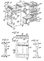
- FIG. 1 shows schematically an interface board utilizing an assembly of interlocked modular blocks in accordance with one form of the invention.
- each of the two rectangular end blocks 10 and 12 contains a pair of counter-bored mounting holes, designated 14, 16 and 18, 20, respectively.
- Suitable mounting screws 19 can be inserted through the holes and screwed into corresponding threaded mounting holes on a supporting frame 21, which may, for example, be an interior wall of an engine compartment.
- This example shows, merely by way of illustration, the use of four side-by-side rectangular modular blocks 10, 22, 24 and 12, a square block 26 mounted to one end of rectangular block 24, and a further rectangular block 28 mounted to the ends of blocks 22 and 24.
- the modular blocks may be assembled in many different ways other than those shown; for example, the rectangular blocks may be mounted to each other in end-to-end configurations, and the square block may be mounted to the short side of either half of a long side of any of the rectangular blocks.
- Another configuration and arrangement of interface board is shown, for example, in Figure 22, and will be referred to in detail later herein.
- each of the blocks has a front face, facing the viewer in Figs. 1 and 2, a rear face on its opposite side, and four side faces.
- the front faces of blocks 22 and 24 are provided with suitable conventional plug-in socket openings such as 30 and 32, into which one may plug any of various electrical elements such as the relay 38 and the circuit breakers 40.
- Block 12 is provided with nine sockets such as 41 into which may be inserted terminal connectors such as 42, secured to the ends of wires such as 43; suitable spring clips such as 43A may be provided in the connectors, and suitable detent structures such as 43B may be provided, extending from the front of block 12, to hold the connectors such as 42 in position once inserted in place, as shown.
- each modular block comprises, along its side faces, sets of locking elements such as set 54 in Fig. 2. It will be seen that in Fig. 2 there are two such sets of locking elements along each of the longer sides of the rectangular blocks and one such set along each of the shorter side faces, each set being identical with the other and the block in this example being substantially twice as long as it is wide.
- Each set such as 54 comprises a bar-like land such as 56 extending parallel to the front-to-rear dimension of the modular block and protruding from its side face on one side of the front-to-back center line A-A' of that set of locking elements. Also provided is a groove 58 extending parallel to the bar-like land 56, the groove and the land being equidistant on opposite sides of the centerline A-A'. Groove 58 is of transverse dimensions such as to snugly receive within it a bar-like land identical with land 56, integrally formed on another side face of one of the other blocks.
- first abutment means 62 providing a rearwardly-facing shoulder 64, and a second abutment means 66 positioned on the opposite side of the centerline A-A' and comprising a shoulder facing forwardly on the end of land 56- the first and second abutment means are disposed equidistantly from and on opposite sides of the center line A-A', so that when a pair of the blocks are placed with their locking elements in mating engagement with each other, these first and second abutment means are thereby positioned adjacent corresponding abutment means of the adjacent block with which it is mated, thereby to prevent sliding motion of one block with respect to the other in either direction parallel to the lands and grooves.
- These comprise, in the first set of locking elements 54, a dovetail mortise 70 recessed into the side edge of block 22, in this case configured symmetrically with respect to the centerline A-A'.
- the mortises of the two will therefore be placed in aligned confronting relationship, so as to provide between them an opening into which the locking wedge to be described hereinafter may be pressed to lock the adjacent blocks to each other against parting motion thereof. Accordingly, by placing the selected modular blocks in mating engagement to provide the interface board desired, and then inserting the locking wedges into place, a customized interface board may be provided at low cost, without requiring special assembly techniques or tools.
- FIG 14 shows the same two blocks 22 and 24 in mating engagement with each other, and illustrates how the locking wedges, in the form of double dovetailed wedges 80 and 82, are inserted into their corresponding mortises to lock the two blocks together against parting motion.
- each locking wedge is held aligned, as shown, and advanced to insert it into the mortises, wherein it is pressed until it wedges itself tightly within the mortises and achieves a locked position therein.
- the form of the mortises and wedges, and the nature of their locking action will be more fully appreciated first from a consideration of the wedge itself as shown in Figs. 10-12, and then from a consideration particularly of Figs. 15-17 showing a wedge in locked position.
- Figs. 10-12 of the typical locking wedge 80 As shown in Fig. 10 in plan view, its side edges taper downwardly in wedge-like fashion toward the left in Fig. 10, which is the direction of its insertion.
- the corresponding mortises such as 24e and 22e are also tapered in this same direction. These tapers provide for easy entry of the smaller ends of the wedges into the mortises; the mortises preferably have slightly greater taper than the wedges so that, as the wedge approaches its fully inserted position, there is a binding action between wedge and mortise which tends to hold the wedge tightly in place after it is fully inserted with its front end abutting the inner end of the mortise.
- the wedge is in the form of a double-sided wedge having two identical dovetail tenons 86,88 and 90,92 on its opposite side edges. It also comprises an integral resilient hooked projection 96 extending from near the middle of its forward end, used to achieve further positive locking, as will presently be described.
- tenons 86 and 88 serve as a dovetail inserted in the mortise 22e of block 22, while tenons 90 and 92 provide a dovetail fit into mortise 24e of block 24.
- the wedge therefore provides two dovetail arrangements, one on each side of the center of the wedge, each mating with a mortise on one of the two adjacent blocks so as to hold the blocks locked against parting motion.
- the wedge 80 is shown fully inserted, so that its forward end abuts against a shoulder 100 at the bottom of the mortise. Furthermore, the hooked end of the projection 96 flexes sufficiently during its insertion to pass the boss 100 on the block 24, and in the position shown has sprung back so that its hooked end engages with the shoulder detent 98 to prevent subsequent withdrawal or accidental pulling out 0 : the wedge after it has been fully inserted to the position shown in Figure 17.
- FIG 22 Another type of interface board which can be similarly put together by means of the present invention is shown schematically in Figure 22, which is made up entirely of square blocks such as 110 plus four mounting structures such as 112 each having sets of locking elements on those side surfaces thereof which engage the adjacent square blocks.
- Figure 18 shows the representative square block 110 of Figure 22, and the adjacent representative mounting block or structure 112.
- Structure 112 is provided with a suitable through-bore at 116 in which a suitable mounting screw 117 (Fig. 21) may be inserted.
- a suitable mounting screw 117 Fig. 21
- Each of its two side faces 118 and 120 is provided with a set of locking elements identical with those of the square blocks adjacent it, including block 110.
- Figures 18-21 also show a modified and preferred arrangement of the locking projection and detent for holding the locking wedge 121 securely in place once fully inserted.
- the resilient locking projection 202 is off-center, as is the detent 204 with which it engages, so that the wedge must be turned to the correct one of its two reversible positions in order for the projection to line up with the detent during and after its insertion.
- a relief 208 of lesser depth than the detent which, when the blocks are mated, leaves an opening behind the resilient projection just sufficient to permit the projection to be forced into its final position, engaging the detent. With this arrangement the projection cannot readily be bent back sufficiently to clear the detent after it is once installed, providing a more permanent final structure.
Landscapes
- Connector Housings Or Holding Contact Members (AREA)
Applications Claiming Priority (2)
| Application Number | Priority Date | Filing Date | Title |
|---|---|---|---|
| US06/636,148 US4611879A (en) | 1984-07-31 | 1984-07-31 | Modular block and electrical interface assemblies employing same |
| US636148 | 1984-07-31 |
Publications (3)
| Publication Number | Publication Date |
|---|---|
| EP0170455A2 true EP0170455A2 (fr) | 1986-02-05 |
| EP0170455A3 EP0170455A3 (en) | 1987-10-14 |
| EP0170455B1 EP0170455B1 (fr) | 1994-04-13 |
Family
ID=24550621
Family Applications (1)
| Application Number | Title | Priority Date | Filing Date |
|---|---|---|---|
| EP85304954A Expired - Lifetime EP0170455B1 (fr) | 1984-07-31 | 1985-07-11 | Bloc modulaire et systèmes électriques de construction utilisant celui-ci |
Country Status (4)
| Country | Link |
|---|---|
| US (1) | US4611879A (fr) |
| EP (1) | EP0170455B1 (fr) |
| CA (1) | CA1234424A (fr) |
| DE (1) | DE3587796T2 (fr) |
Cited By (12)
| Publication number | Priority date | Publication date | Assignee | Title |
|---|---|---|---|---|
| DE4114921A1 (de) * | 1991-05-07 | 1992-11-12 | Ahlborn Mess Und Regelungstech | Elektrische steckverbindung |
| EP0593862A1 (fr) * | 1992-10-23 | 1994-04-27 | F. Wieland Elektrische Industrie GmbH | Boîtier de connection pour appareils électriques |
| EP0508059A3 (fr) * | 1991-04-08 | 1994-05-04 | Codognese Meccanotec | |
| WO1997017741A1 (fr) * | 1995-11-09 | 1997-05-15 | The Whitaker Corporation | Coupleur mecanique |
| FR2742004A1 (fr) * | 1995-12-05 | 1997-06-06 | Sylea | Boite de connexion |
| US5807119A (en) * | 1996-11-08 | 1998-09-15 | Baechtle; David Robert | Mechanical coupling device |
| EP0810690A3 (fr) * | 1996-05-28 | 1998-10-28 | Plasticos Mondragon, S.A. | Bloc modulaire de connexion, coupage et test pour lignes téléphoniques |
| FR2799338A1 (fr) * | 1999-10-05 | 2001-04-06 | Sylea | Ensemble de modules pour la realisation de boites a fusibles |
| EP2892110A1 (fr) * | 2014-01-06 | 2015-07-08 | Hamilton Sundstrand Corporation | Diviseur de bloc terminal à champs remplaçable |
| WO2016162463A1 (fr) * | 2015-04-10 | 2016-10-13 | Phoenix Contact Gmbh & Co. Kg | Système de rangement en nid d'abeille |
| WO2017174728A1 (fr) * | 2016-04-08 | 2017-10-12 | Phoenix Contact Gmbh & Co. Kg | Bloc de jonction en nid d'abeilles |
| WO2018178401A1 (fr) * | 2017-03-31 | 2018-10-04 | Igus Gmbh | Système modulaire pour modules de connecteur enfichable, unité de connecteur enfichable et cadre de boîtier modulaire associé |
Families Citing this family (32)
| Publication number | Priority date | Publication date | Assignee | Title |
|---|---|---|---|---|
| KR900003934A (ko) * | 1987-08-19 | 1990-03-27 | 나가오 다게시 | 전자접촉기의 연결장치 |
| US5033978A (en) * | 1990-06-21 | 1991-07-23 | Northern Telecom Limited | Telecommunications connector housing |
| DE9013646U1 (de) * | 1990-09-28 | 1990-12-20 | Siemens AG, 80333 München | Verteilerleiste für Telekommunikationsanlagen zur Verbindung von ankommenden und abgehenden Leitungsadern |
| USD352685S (en) | 1992-09-28 | 1994-11-22 | Issa Darrell E | Slide-together relay socket |
| US5295870A (en) * | 1992-12-11 | 1994-03-22 | Electro-Wire Products, Inc. | Modular electrical assembly and removable wedge therefor |
| DE4425466A1 (de) * | 1994-07-19 | 1996-01-25 | Thomas & Betts Gmbh | Kabel-Steckverbinder |
| US5587890A (en) | 1994-08-08 | 1996-12-24 | Cooper Industries, Inc. | Vehicle electric power distribution system |
| JPH11502054A (ja) * | 1995-03-16 | 1999-02-16 | ザ ウィタカー コーポレーション | モジュラフレーム組立体 |
| DE19535822A1 (de) * | 1995-09-26 | 1997-03-27 | Amp Holland | Anordnung zum Verbinden von einem elektrischen Stecker mit einem komplementären Stecker |
| DE19613748A1 (de) * | 1996-04-01 | 1997-10-02 | Taller Gmbh | Mehrpolige Anschlußklemmleiste zur ortsfesten Befestigung an einer Gehäusewandung für elektrische Geräte |
| US6059615A (en) * | 1997-01-31 | 2000-05-09 | Berg Technology, Inc. | Modular cable to board power connector |
| DE29703565U1 (de) * | 1997-02-27 | 1997-04-30 | Siemens AG, 80333 München | Verbindungselement zum Verbinden von Einzelschützen zu einer Schützkombination |
| USD405055S (en) * | 1997-06-09 | 1999-02-02 | Cliff Electronic Components Limited | Electrical terminal housing |
| JP3494917B2 (ja) * | 1999-03-31 | 2004-02-09 | 矢崎総業株式会社 | 圧接ジョイントコネクタ |
| DE29917684U1 (de) * | 1999-10-07 | 2000-02-17 | TRW Automotive Electronics & Components GmbH & Co. KG, 78315 Radolfzell | Mehrfachschalter |
| JP4056225B2 (ja) * | 2001-02-08 | 2008-03-05 | 矢崎総業株式会社 | 電気接続箱の製造方法および電気接続箱 |
| ATE393464T1 (de) | 2002-02-14 | 2008-05-15 | Mta Spa | Modulare struktur zum halten von sicherungen und modularer sicherungshalter |
| CN200959416Y (zh) * | 2006-09-15 | 2007-10-10 | 富士康(昆山)电脑接插件有限公司 | 电连接器 |
| TWI334672B (en) * | 2007-07-06 | 2010-12-11 | Ks Terminals Inc | Electrical connector and conducting terminal and fabrication method thereof |
| CN102055109B (zh) * | 2009-10-27 | 2013-07-03 | 鸿富锦精密工业(深圳)有限公司 | 连接座 |
| CN102543616A (zh) * | 2011-12-14 | 2012-07-04 | 潍坊胜科电气有限公司 | 一种可扩展组合型保险装置 |
| US9437954B2 (en) * | 2013-04-26 | 2016-09-06 | Interconnect Devices, Inc. | Series connector |
| US20140357095A1 (en) * | 2013-06-03 | 2014-12-04 | Toyota Motor Engineering & Manufacturing North America, Inc. | Block connector holder |
| DE102015105546A1 (de) * | 2015-04-10 | 2016-10-13 | Phoenix Contact Gmbh & Co. Kg | Wabenbaustein |
| DE102015105548A1 (de) * | 2015-04-10 | 2016-10-13 | Phoenix Contact Gmbh & Co. Kg | Rangierwabe |
| DE102016106479A1 (de) | 2016-04-08 | 2017-10-12 | Phoenix Contact Gmbh & Co. Kg | Rangierwabe |
| JP6886971B2 (ja) * | 2016-05-24 | 2021-06-16 | 日本端子株式会社 | コネクタ構造 |
| DE102016119061B4 (de) * | 2016-10-07 | 2021-06-10 | Phoenix Contact Gmbh & Co. Kg | Rangierwabe mit gebildeter Haltenut für Markierungsschilder und Wabenbaustein |
| JP7097300B2 (ja) * | 2016-11-30 | 2022-07-07 | 古河電気工業株式会社 | 電気接続カセット |
| DE102017108430B4 (de) * | 2017-04-20 | 2021-09-30 | Harting Electric Gmbh & Co. Kg | Halterahmen für einen schweren Steckverbinder sowie System |
| EP3413415A1 (fr) * | 2017-06-09 | 2018-12-12 | Schneikel Electronics GmbH | Barre multiprise et système de fixation associé |
| DE202020100373U1 (de) * | 2020-01-24 | 2021-04-27 | WAGO Verwaltungsgesellschaft mit beschränkter Haftung | Set aus einem Leiteranschlusselement und einem Befestigungselement |
Family Cites Families (24)
| Publication number | Priority date | Publication date | Assignee | Title |
|---|---|---|---|---|
| US2326327A (en) * | 1941-10-31 | 1943-08-10 | Ford Motor Co | Connector |
| US2463826A (en) * | 1944-02-15 | 1949-03-08 | James H Cannon | Coupler and terminal block |
| US2726375A (en) * | 1951-12-17 | 1955-12-06 | Gordon James | Multiple terminal block |
| FR1232356A (fr) * | 1959-03-28 | 1960-10-07 | Dispositifs d'agrafage des connecteurs | |
| NL298483A (fr) * | 1962-09-27 | |||
| US3259870A (en) * | 1963-03-06 | 1966-07-05 | Albert & J M Anderson Mfg Co | Electrical connector |
| GB1029090A (en) * | 1963-12-27 | 1966-05-11 | Lucas Industries Ltd | Plug and socket connectors |
| US3325771A (en) * | 1964-04-09 | 1967-06-13 | Elco Corp | Electrical connector module with adjustable polarization |
| GB1066672A (en) * | 1964-04-16 | 1967-04-26 | Northrop Corp | A match-determining key device for mating electrical components |
| GB1132584A (en) * | 1965-02-03 | 1968-11-06 | Keyswitch Relays Ltd | Electrical plug and socket assemblies |
| US3344392A (en) * | 1965-02-08 | 1967-09-26 | Briscoe Mfg Company | Electrical terminal connector |
| US3358266A (en) * | 1965-03-17 | 1967-12-12 | Itt | Positive retention disconnectable wire splice |
| US3474397A (en) * | 1967-06-19 | 1969-10-21 | Thomas & Betts Corp | Modular terminal block |
| FR96413E (fr) * | 1968-10-18 | 1972-06-30 | Cie Generale Entpr Elec | Éléments modulaires de traversée et application de tels éléments aux raccordements électriques. |
| DE1923128A1 (de) * | 1969-05-06 | 1970-11-19 | Brawa Artur Braun Fa | Kabelklemmkoerpergesteck fuer Schwachstrom,vorzugsweise fuer Spielzeug |
| US3771104A (en) * | 1971-08-10 | 1973-11-06 | M Clark | Modular element for a solderless expandable terminal strip |
| FR2262873B1 (fr) * | 1974-03-01 | 1977-09-23 | Carpano & Pons | |
| US4046452A (en) * | 1975-04-16 | 1977-09-06 | Amp Incorporated | Electrical connector housing having an improved locking means |
| DE2715861C3 (de) * | 1977-04-09 | 1980-04-24 | Ellenberger & Poensgen Gmbh, 8503 Altdorf | Klemmbrett für die Halterung nebeneinander aufgereihter elektrischer Installationsgeräte |
| US4171862A (en) * | 1977-04-09 | 1979-10-23 | Ellenberger & Poensgen Gmbh | Terminal board for electrical equipment |
| US4269470A (en) * | 1979-08-17 | 1981-05-26 | Ustin Martin D | Modular electrical terminal board |
| US4343528A (en) * | 1980-04-25 | 1982-08-10 | Amp Incorporated | Modular interconnect system |
| US4469393A (en) * | 1981-10-02 | 1984-09-04 | Westinghouse Electric Corp. | Modular connector |
| US4466687A (en) * | 1982-05-20 | 1984-08-21 | Amp Incorporated | Low profile connector providing high density application |
-
1984
- 1984-07-31 US US06/636,148 patent/US4611879A/en not_active Expired - Lifetime
-
1985
- 1985-07-04 CA CA000486303A patent/CA1234424A/fr not_active Expired
- 1985-07-11 DE DE3587796T patent/DE3587796T2/de not_active Expired - Lifetime
- 1985-07-11 EP EP85304954A patent/EP0170455B1/fr not_active Expired - Lifetime
Cited By (23)
| Publication number | Priority date | Publication date | Assignee | Title |
|---|---|---|---|---|
| EP0508059A3 (fr) * | 1991-04-08 | 1994-05-04 | Codognese Meccanotec | |
| DE4114921A1 (de) * | 1991-05-07 | 1992-11-12 | Ahlborn Mess Und Regelungstech | Elektrische steckverbindung |
| EP0593862A1 (fr) * | 1992-10-23 | 1994-04-27 | F. Wieland Elektrische Industrie GmbH | Boîtier de connection pour appareils électriques |
| WO1997017741A1 (fr) * | 1995-11-09 | 1997-05-15 | The Whitaker Corporation | Coupleur mecanique |
| FR2742004A1 (fr) * | 1995-12-05 | 1997-06-06 | Sylea | Boite de connexion |
| EP0810690A3 (fr) * | 1996-05-28 | 1998-10-28 | Plasticos Mondragon, S.A. | Bloc modulaire de connexion, coupage et test pour lignes téléphoniques |
| US5807119A (en) * | 1996-11-08 | 1998-09-15 | Baechtle; David Robert | Mechanical coupling device |
| FR2799338A1 (fr) * | 1999-10-05 | 2001-04-06 | Sylea | Ensemble de modules pour la realisation de boites a fusibles |
| EP1091380A1 (fr) * | 1999-10-05 | 2001-04-11 | Société SYLEA | Ensemble de modules pour la réalisation de boítes à fusibles |
| US20150194750A1 (en) * | 2014-01-06 | 2015-07-09 | Hamilton Sundstrand Corporation | Field-replaceable terminal block divider |
| EP2892110A1 (fr) * | 2014-01-06 | 2015-07-08 | Hamilton Sundstrand Corporation | Diviseur de bloc terminal à champs remplaçable |
| JP2015130336A (ja) * | 2014-01-06 | 2015-07-16 | ハミルトン・サンドストランド・コーポレイションHamilton Sundstrand Corporation | 現場で交換可能な端子台デバイダ |
| US9502794B2 (en) | 2014-01-06 | 2016-11-22 | Hamilton Sundstrand Corporation | Field-replaceable terminal block divider |
| WO2016162463A1 (fr) * | 2015-04-10 | 2016-10-13 | Phoenix Contact Gmbh & Co. Kg | Système de rangement en nid d'abeille |
| EP3281254B1 (fr) * | 2015-04-10 | 2023-11-15 | Phoenix Contact GmbH & Co. KG | Système de rangement en nid d'abeille |
| JP2019514171A (ja) * | 2016-04-08 | 2019-05-30 | フェニックス コンタクト ゲゼルシャフト ミット ベシュレンクテル ハフツング ウント コンパニー コマンディートゲゼルシャフトPhoenix Contact GmbH & Co.KG | パッチボード |
| RU2690957C1 (ru) * | 2016-04-08 | 2019-06-07 | Фёникс Контакт Гмбх Унд Ко. Кг | Упорядоченная ячеистая структура |
| US10374352B2 (en) | 2016-04-08 | 2019-08-06 | Phoenix Contact Gmbh & Co. Kg | Patchboard |
| WO2017174728A1 (fr) * | 2016-04-08 | 2017-10-12 | Phoenix Contact Gmbh & Co. Kg | Bloc de jonction en nid d'abeilles |
| WO2018178401A1 (fr) * | 2017-03-31 | 2018-10-04 | Igus Gmbh | Système modulaire pour modules de connecteur enfichable, unité de connecteur enfichable et cadre de boîtier modulaire associé |
| CN110637397A (zh) * | 2017-03-31 | 2019-12-31 | 易格斯有限公司 | 用于插接连接器模块的积木系统、插接连接器单元和用于插接连接器单元的模块式壳体框架 |
| CN110637397B (zh) * | 2017-03-31 | 2021-12-07 | 易格斯有限公司 | 用于插接连接器模块的积木系统、插接连接器单元和用于插接连接器单元的模块式壳体框架 |
| US11374348B2 (en) | 2017-03-31 | 2022-06-28 | Igus Gmbh | Modular system for plug connector modules, plug connector unit and modular housing frames for same |
Also Published As
| Publication number | Publication date |
|---|---|
| DE3587796T2 (de) | 1994-11-24 |
| US4611879A (en) | 1986-09-16 |
| CA1234424A (fr) | 1988-03-22 |
| EP0170455A3 (en) | 1987-10-14 |
| EP0170455B1 (fr) | 1994-04-13 |
| DE3587796D1 (de) | 1994-05-19 |
Similar Documents
| Publication | Publication Date | Title |
|---|---|---|
| US4611879A (en) | Modular block and electrical interface assemblies employing same | |
| US6004158A (en) | Electrical connector with secondary locking plates | |
| US4368939A (en) | Modular connector housing | |
| US3848951A (en) | Connector housings and locking structures therefor | |
| US4655525A (en) | Means for retaining terminals in a connector | |
| US5184964A (en) | Panel lock for a float mount connector | |
| US4560227A (en) | Fuseholder for blade-type fuses | |
| US4171862A (en) | Terminal board for electrical equipment | |
| EP0731530B1 (fr) | Connecteur assemblé | |
| US4596436A (en) | Electrical connector housing assembly comprising housing frame containing housing modules | |
| US5211585A (en) | Electrical connector housings having polarizing means | |
| US5007888A (en) | Electrical interconnection assembly | |
| US5213518A (en) | Connecting electrical bus bars to electrical circuitry | |
| US5197896A (en) | Float mounting an electrical connector | |
| US5203722A (en) | Double-lock electrical connector | |
| US4682839A (en) | Multi-row modular electrical connector | |
| EP0644626A2 (fr) | Système de codage pour connecteur électrique | |
| CA2099092A1 (fr) | Fiche et prise electriques codees configurables | |
| US5468156A (en) | Locking system for interconnection of daughter board and mother board assemblies | |
| GB2077051A (en) | Midular electrical plug and socket connectors | |
| GB2248350A (en) | Double-lock for contact in an electrical connector | |
| US6878017B2 (en) | Joint connector and method of assembling it | |
| US6162068A (en) | Electrical connector assembly | |
| US4747792A (en) | Multi-pole plug connector with coding system | |
| US5370557A (en) | Keying system for low profile connector |
Legal Events
| Date | Code | Title | Description |
|---|---|---|---|
| PUAI | Public reference made under article 153(3) epc to a published international application that has entered the european phase |
Free format text: ORIGINAL CODE: 0009012 |
|
| AK | Designated contracting states |
Designated state(s): DE FR GB SE |
|
| PUAL | Search report despatched |
Free format text: ORIGINAL CODE: 0009013 |
|
| AK | Designated contracting states |
Kind code of ref document: A3 Designated state(s): DE FR GB SE |
|
| 17P | Request for examination filed |
Effective date: 19880311 |
|
| 17Q | First examination report despatched |
Effective date: 19900925 |
|
| GRAA | (expected) grant |
Free format text: ORIGINAL CODE: 0009210 |
|
| RAP1 | Party data changed (applicant data changed or rights of an application transferred) |
Owner name: FARGO ASSEMBLY OF PA, INC. |
|
| AK | Designated contracting states |
Kind code of ref document: B1 Designated state(s): DE FR GB SE |
|
| PG25 | Lapsed in a contracting state [announced via postgrant information from national office to epo] |
Ref country code: SE Free format text: THE PATENT HAS BEEN ANNULLED BY A DECISION OF A NATIONAL AUTHORITY Effective date: 19940413 Ref country code: FR Effective date: 19940413 |
|
| REF | Corresponds to: |
Ref document number: 3587796 Country of ref document: DE Date of ref document: 19940519 |
|
| EN | Fr: translation not filed | ||
| PLBE | No opposition filed within time limit |
Free format text: ORIGINAL CODE: 0009261 |
|
| STAA | Information on the status of an ep patent application or granted ep patent |
Free format text: STATUS: NO OPPOSITION FILED WITHIN TIME LIMIT |
|
| 26N | No opposition filed | ||
| REG | Reference to a national code |
Ref country code: GB Ref legal event code: IF02 |
|
| PGFP | Annual fee paid to national office [announced via postgrant information from national office to epo] |
Ref country code: GB Payment date: 20040707 Year of fee payment: 20 |
|
| PGFP | Annual fee paid to national office [announced via postgrant information from national office to epo] |
Ref country code: DE Payment date: 20040722 Year of fee payment: 20 |
|
| PG25 | Lapsed in a contracting state [announced via postgrant information from national office to epo] |
Ref country code: GB Free format text: LAPSE BECAUSE OF EXPIRATION OF PROTECTION Effective date: 20050710 |
|
| REG | Reference to a national code |
Ref country code: GB Ref legal event code: PE20 |