EP0170459B1 - Lebensmittelschneidevorrichtung - Google Patents
Lebensmittelschneidevorrichtung Download PDFInfo
- Publication number
- EP0170459B1 EP0170459B1 EP85305013A EP85305013A EP0170459B1 EP 0170459 B1 EP0170459 B1 EP 0170459B1 EP 85305013 A EP85305013 A EP 85305013A EP 85305013 A EP85305013 A EP 85305013A EP 0170459 B1 EP0170459 B1 EP 0170459B1
- Authority
- EP
- European Patent Office
- Prior art keywords
- rod
- supporting
- plate
- cutting
- worm wheel
- Prior art date
- Legal status (The legal status is an assumption and is not a legal conclusion. Google has not performed a legal analysis and makes no representation as to the accuracy of the status listed.)
- Expired
Links
- 238000005520 cutting process Methods 0.000 title claims description 68
- 235000013305 food Nutrition 0.000 description 10
- 239000000126 substance Substances 0.000 description 5
- 230000007547 defect Effects 0.000 description 3
- 239000010794 food waste Substances 0.000 description 2
- 230000004048 modification Effects 0.000 description 2
- 238000012986 modification Methods 0.000 description 2
- 229920003023 plastic Polymers 0.000 description 2
- 239000004033 plastic Substances 0.000 description 2
- 235000021055 solid food Nutrition 0.000 description 2
- 208000027418 Wounds and injury Diseases 0.000 description 1
- 238000010276 construction Methods 0.000 description 1
- 230000006378 damage Effects 0.000 description 1
- 239000000428 dust Substances 0.000 description 1
- 235000013399 edible fruits Nutrition 0.000 description 1
- 230000000694 effects Effects 0.000 description 1
- 235000015203 fruit juice Nutrition 0.000 description 1
- 208000014674 injury Diseases 0.000 description 1
- 239000000463 material Substances 0.000 description 1
- 230000002093 peripheral effect Effects 0.000 description 1
- 229910001220 stainless steel Inorganic materials 0.000 description 1
- 239000010935 stainless steel Substances 0.000 description 1
- 238000005406 washing Methods 0.000 description 1
Images




Classifications
-
- B—PERFORMING OPERATIONS; TRANSPORTING
- B26—HAND CUTTING TOOLS; CUTTING; SEVERING
- B26D—CUTTING; DETAILS COMMON TO MACHINES FOR PERFORATING, PUNCHING, CUTTING-OUT, STAMPING-OUT OR SEVERING
- B26D3/00—Cutting work characterised by the nature of the cut made; Apparatus therefor
- B26D3/24—Cutting work characterised by the nature of the cut made; Apparatus therefor to obtain segments other than slices, e.g. cutting pies
- B26D3/26—Cutting work characterised by the nature of the cut made; Apparatus therefor to obtain segments other than slices, e.g. cutting pies specially adapted for cutting fruit or vegetables, e.g. for onions
-
- A—HUMAN NECESSITIES
- A23—FOODS OR FOODSTUFFS; TREATMENT THEREOF, NOT COVERED BY OTHER CLASSES
- A23G—COCOA; COCOA PRODUCTS, e.g. CHOCOLATE; SUBSTITUTES FOR COCOA OR COCOA PRODUCTS; CONFECTIONERY; CHEWING GUM; ICE-CREAM; PREPARATION THEREOF
- A23G9/00—Frozen sweets, e.g. ice confectionery, ice-cream; Mixtures therefor
- A23G9/04—Production of frozen sweets, e.g. ice-cream
- A23G9/045—Production of frozen sweets, e.g. ice-cream of slush-ice, e.g. semi-frozen beverage
-
- B—PERFORMING OPERATIONS; TRANSPORTING
- B26—HAND CUTTING TOOLS; CUTTING; SEVERING
- B26D—CUTTING; DETAILS COMMON TO MACHINES FOR PERFORATING, PUNCHING, CUTTING-OUT, STAMPING-OUT OR SEVERING
- B26D7/00—Details of apparatus for cutting, cutting-out, stamping-out, punching, perforating, or severing by means other than cutting
- B26D7/06—Arrangements for feeding or delivering work of other than sheet, web, or filamentary form
-
- B—PERFORMING OPERATIONS; TRANSPORTING
- B26—HAND CUTTING TOOLS; CUTTING; SEVERING
- B26D—CUTTING; DETAILS COMMON TO MACHINES FOR PERFORATING, PUNCHING, CUTTING-OUT, STAMPING-OUT OR SEVERING
- B26D7/00—Details of apparatus for cutting, cutting-out, stamping-out, punching, perforating, or severing by means other than cutting
- B26D7/22—Safety devices specially adapted for cutting machines
- B26D7/24—Safety devices specially adapted for cutting machines arranged to disable the operating means for the cutting member
-
- B—PERFORMING OPERATIONS; TRANSPORTING
- B26—HAND CUTTING TOOLS; CUTTING; SEVERING
- B26D—CUTTING; DETAILS COMMON TO MACHINES FOR PERFORATING, PUNCHING, CUTTING-OUT, STAMPING-OUT OR SEVERING
- B26D7/00—Details of apparatus for cutting, cutting-out, stamping-out, punching, perforating, or severing by means other than cutting
- B26D7/26—Means for mounting or adjusting the cutting member; Means for adjusting the stroke of the cutting member
- B26D7/2628—Means for adjusting the position of the cutting member
Definitions
- the present invention relates to a food-cutting apparatus for solid foods such as ice blocks, frozen fruits and the like.
- FIG. 1 is an upper frame; 2 is a boss provided in a central portion of a back surface of the frame 1; 3 is a cylindrical shaft housing; 4 is a rotary shaft; 5 is a pulley fixed to a lower end of the rotary shaft 4; 6 is a supporting arm; 7 is a driving electric motor; 8 is a pulley mounted on a shaft of the electric motor 7; 9 is a belt running under tension around the pulleys 5 and 8; 11 is a cutting plate; 12 is an opening provided in the cutting plate 11; 13 is a cutting blade arranged to protrude at its front tip from the opening 12; 15 is a transfer rotor; 16 is a boss; 17 is a bush; 18 is a nut; 20 is a hopper; 21 is an anti-scatter cover disposed over the hopper 20
- This food-cutting apparatus is so constructed that, when its food-cutting operation has finished, it is possible to wash out any residue of cut foods adhering to the transfer rotor 15 and the cutting plate 11, by opening the lid 24, removing in turn the head cover 22 and the anti-scatter cover 21, and then dismounting the transfer motor 15 and the cutting plate 11 from the frame 1.
- FIG. 2 shows a cutting blade mounting portion 32 of this earlier apparatus.
- a supporting plate 34 is fixed to a back surface of the cutting plate 11, near the opening 12, through mounts 33 by means of bolts 35, and a pair of arms 36 are provided on the surface of the supporting plate 34 remote from the cutting plate 11, between the front ends of which arms 36 a supporting rod 37 is pivotally supported.
- the supporting rod 37 is mounted in a central boss portion 39 of a mounting plate 38 for the cutting blade 13, and the cutting blade 13 is fixed to a front bent portion of the plate 38 by means of bolts 40.
- Another bolt 42 has a threaded front portion thereof engaging with a female screw (not shown) of an adjusting knob 45 through an opening 43 provided in a rear portion of the mounting plate 38, to adjust the amount of the front tip of the cutting blade which protrudes through the opening 12 by rotating the adjusting knob 4 to thereby slightly rotate the plate 38 on the supporting rod 37.
- the reference numeral 46 designates a spring interposed between the supporting plate 34 and the mounting plate 38.
- reference numeral 51 designates a base on one side of which is mounted an upstanding supporting frame 52, at an upper portion of which is mounted an upper frame 53 extending laterally from the supporting frame 52. Within an upper portion of the supporting frame 52 an electric motor 55 is mounted. These frames 52 and 53 are covered by a head cover 54.
- a main shaft 57 on an outer peripheral surface of which a worm is formed, is rotatably mounted on a supporting member 60 provided on the upper frame 53, and a pulley 56 is slidably connected to an upper portion of the main shaft 57 by means of a key or the like.
- a belt 59 runs under tension around pulley 56 and another pulley 58 mounted on a shaft of the electric motor 55.
- a holding member 62 To a lower end of the main shaft 57 is attached a holding member 62, below which is disposed a cutting plate 63 to which a cutting blade 13 is detachably secured.
- a worm wheel 65 meshing with the worm of the main shaft 57 is fixed to a rotary shaft 66 which is rotatably supported by a supporting member 64 provided on the upper frame 3, adjacent to which worm wheel 65 a brake ring 67 (Fig. 4) is also fixed to the rotary shaft 66.
- On the upper frame 53 On the upper frame 53 is mounted a supporting member 68 through which a threaded hole extends laterally.
- a screw shaft 70 is engaged in the hole, and a front end portion of the screw shaft 70 has a blind bore into which a small- diameter supporting shaft 71 of a brake shoe 69 is inserted.
- a coil spring 72 is wound to press the brake shoe 69 on to the brake ring 67.
- the numeral 73 designates a main switch for actuating the motor 55.
- 75 designates a lower cover provided between the upper frame 53 and the cutting plate 63 to enclose the cutting area, which cover 75 has its rear half portion 75b attached to the supporting frame 52 by means of mounting means 76, and its front half portion 75a, which is of smaller radius than the rear half portion 75b, inserted at its lower end in a concave groove provided in the cutting plate 63 to make it horizontally openable.
- Numeral 77 designates a manual operating handle fixed to an outwardly extending end of the rotary shaft 66.
- the worm wheel 65 is rotated by turning the rotary shaft 66 by the manual handle 77, to move the main shaft 57 up so as to form a space between the holding member 62 and the cutting plate 63. Then the lower cover 65 is opened to place a work-piece in the form of some food in the space just mentioned, and thereafter the holding member 62 is lowered, by rotating the handle 77 in the reverse direction, to pierce the food with holding pins 79 provided on the lower surface of the holding member 62.
- the motor 55 When cutting food with this apparatus, the motor 55 is actuated by turning on the main switch 73 after closing the lower cover 75, and the motor 55 then drives the main shaft through the pulleys 56, 58 and the belt 59. Since the worm wheel 65 is prevented from rotating by the braking force of the brake shoe 69, the main shaft 57 is lowered when rotated by the motor 55, to press downward and rotate the food by means of the holding member 62, so that the food is cut by the cutting blade 13. At this time the food resists the downward movement of the main shaft 57, and this resisting force is overcome when the worm wheel 65, meshing with the worm of the main shaft 57, is rotated by the driving force of the motor 55 against the braking force of the brake shoe 69.
- the main switch 73 may be turned on when the lower cover 75 is still not closed completely, due for example to a user's carelessness and the user turning the main switch on by mistake. This can lead to an accident, for example from a piece of cut food striking a worker near the apparatus, or in a user's injury caused by his touching the holding member 62. This is another defect inherent in this known apparatus.
- An object of the invention is to provide a food-cutting apparatus in which an accidental downward movement of the aforementioned holding member is prevented, by securing the holding down member in a upward position of its movement when desired.
- Figs. 5A, 5B, 5C and 5D show details of the holding member 62.
- a base plate 78 made of plastic, in which the holding pins 79 are integrally embedded when the base plate 78 is molded.
- the total number of holding pins 79 is eight, four of which are provided in a radially inner portion of the base plate and remaining four of which are provided in a radially outer portion thereof.
- the total number of holdings pins 79 is not however restricted to eight only.
- Reference numerals 82 designates a cover fitted to the base plate 78, in a central portion of which cover is provided a threaded hole 80 with which a lower end of the main work shaft 57 engages.
- the cover 82 is secured to the base plate 78 by means of set screws 83 which engage in threaded holes 84.
- the holding pins 79 are integrally embedded in the base plate 78 of the holding member 62, it is difficult to remove any food residue which adheres to the root portions of the holding pins 79 adjacent the underneath surface of the base plate 78, and to portions between the cover 82 and the base plate 78. This is yet another defect inherent in this known food-cutting apparatus.
- another object of the present invention is to provide a mounting means for a cutting blade of a food-cutting apparatus for solid foods, which mounting means enables a mounting plate for the cutting blade and a supporting plate to be disassembled from the apparatus so as to wash out substances adhered to the above- mentioned members, thereby to resolve or at least reduce the problems inherent in the known food-cutting apparatus.
- the present invention is characterised in that a supporting plate is fixed to said back surface of said cutting plate near to said opening and between said cutting plate and said mounting plate, said pair of arms being provided on an outer surface of said supporting plate, in that said mounting plate is mounted on said supporting rod by way of an engaging recess formed in a central portion of the mounting plate on the side of said supporting rod facing said supporting plate, spring means being interposed between said mounting plate and said supporting plate rearwardly of said engaging recess to urge said mounting plate into engagement with said supporting rod, and that the apparatus further comprises a stop means having a front end engaging portion engageable with said worm wheel, said stop means being so supported that said front end engaging portion is movable between a first position where it engages with said worm wheel and a second position where it does not; and a supporting member for said stop means, said supporting member being disposed on said upper frame.
- the mounting plate can be pulled out of the apparatus once the cutting blade has been removed from the mounting plate and the adjusting means has also been removed. Consequently it is possible to completely wash away any substances adhered to the facing inner sides of the mounting plate and the supporting plate, when the cutting blade is being washed. This enables the apparatus to provide cut foods in a sanitary manner and to be assembled and disassembled easily and quickly, thereby to enhance the workability of the apparatus.
- the stop means when the said holding down member is held in a stationary position, the stop means may be moved to the said first position to engage with the worm wheel so as to prevent the worm wheel from rotating, whereby up and down movement of the main shaft is prevented.
- the stop means when it is desired to move the main shaft up and down, the stop means may be moved to the said second position where the engagement between the stop means and the worm wheel is released to enable the worm wheel to rotate freely.
- the said stop means includes a rod which is both rotatable and slidable in a hole extending through said supporting member, said front end engaging portion being formed at the front end of said rod and having an inclined end surface engageable with said worm wheel, behind which engaging portion is formed a flange, a coil spring being mounted around said rod between said flange and said supporting member to bias said rod towards said worm wheel, said rod being movable between said first and second positions wherein said inclined end surface is directed up and down respectively by rotation of said rod, and a stop pin on said rod which engages with a rear surface of said supporting member in said first position and said second position.
- the said stop means includes a rod which is both rotatable and slidable in a hole extending through said supporting member, said front end engaging portion being formed at the front end of said rod, a flange behind said engaging portion, a coil spring encircling said rod between said flange and said supporting member to bias said rod toward said worm wheel, and a transverse pin in a rear portion of said rod, said supporting member having an opening in a rear side thereof mounting a sleeve formed with a long slot in which said pin is insertable.
- Another subsidiary object of the invention is to provide a food-cutting apparatus in which the electric motor cannot be actuated, thereby to prevent the holding member from rotating, when the lower cover is open.
- This may be accomplished by providing, at a lower end of said upper frame, a sub-switch for on-off operation controlled by opening and closing of said cover, which sub-switch is connected in series with said main switch in said control circuit for said electric motor. Then, since the sub-switch is turned off by opening the lower cover, the electric motor cannot be actuated even if the user turns on the main switch by mistake, and as a result the cutting operation cannot be started.
- a further subsidiary object of the invention is to provide a food-cutting apparatus in which there is no fear of causing sanitary problems because food residue adhered to root portions of the holding pins adjacent the base plate, and also adhered between the cover and the base plate, can be easily removed.
- This may be accomplished by forming the holding member as a base plate, a plurality of holding pins and a cover, which base plate is provided with a plurality of through-holes in which said plurality of holding pins are inserted. Then, when it is desired to wash out the holding member, such member is first disconnected from the main shaft and thereafter disassembled into the base plate, the holding pins and the cover to enable such parts to be easily washed out.
- reference numeral 90 designates a mounting device for a cutting blade 13, the device 90 including a supporting plate 92 fixed to a back surface of a cutting plate 128, near to an opening 131 therein, by means of mounts 91 and bolts 93.
- a pair of arms 95 are fixed to the outside surface of the supporting plate 92 by means of bolts 94, between which arms 95 a supporting rod 96 is mounted by inserting its opposite ends into transverse holes provided in the arms 95.
- a circular arc-shaped engaging recess 99 formed in a central portion of a mounting plate 98 partly embraces the supporting rod 96 so that the plate 98 is pivotable on the supporting rod 96 acting as a center of rotation thereof. As shown in Fig.
- the cutting blade 13 is releasably connected to a front bent portion of the mounting plate 98 by means of bolts 100.
- the supporting plate 92 carries a bolt 101 which threadedly engages with a female screw 106 of a sleeve 105 mounted in an end bore of an adjusting knob 103, via a notch 102 formed in a rear portion of the mounting plate 98.
- a spring 107 is interposed between the supporting plate 92 and the mounting plate 98 to urge the mounting plate 98 into engagement with the supporting rod 96. Rotation of the adjusting knob 103 adjusts the position of the cutting blade 13.
- the bolts 100 are first removed to dismount the cutting blade 13 from its mounting plate 98, and then the adjusting knob 103 is turned to disengage the bolt 102 from the sleeve 105. Then, when the spring 107 has been removed, it is possible to pull out the mounting plate 98 from its position between the arms 95, to separate the mounting plate from the supporting plate 92.
- Figs. 9 to 17C show an embodiment of a food-cutting apparatus according to the present invention.
- like reference numerals designate parts similar to those of the known food-cutting apparatus shown in Fig. 3 and already described above.
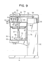
- FIG. 9 shows an embodiment of a food-cutting apparatus according to the present invention.
- This embodiment of the present invention differs from the apparatus of Fig. 3 mainly in that it is provided with a stop means 135 (135'), a sub-switch 151, an improved construction of the lower cover 75, and a holding member 161 which replaces the known type of holding member 62.
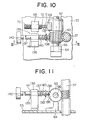
- Figs. 10 and 11 show details of the stop means 135.
- a supporting member 136 is mounted on the upper frame 53 side by side with the supporting member 68, which frame 53 and member 68 have already been described above.
- a throughhole is formed in the supporting member 136, in which a rod 137 is rotatably and slidably fitted.
- an engaging portion 138 having an inclined surface which engages with the worm wheel 65 in the manner of a pawl.
- Behind the portion 138 a flange 139 is provided.
- a coil spring 140 acting between the flange 139 and the supporting member 136 biases the rod 137 towards the worm wheel 65.
- a stop pin 141 is provided to abut on a back surface of the supporting member 136 when the engaging portion 138 engages with the worm wheel 65.
- a knob 142 is provided at the rear end of the rod 137 .
- a first position where the stop means 135 engages with the worm wheel 65 is shown with solid lines.
- the engaging portion 138 engages with the worm wheel 65, and the stop pin 141 abuts on the back surface of the supporting member 136, this being a stable condition. If it is required to change this condition, it is enough to pull the rod 137 rearward and to turn the same by a half-turn by means of the knob 142, so as to bring the engaging portion 138 to a second position shown with chain lines in Fig. 11, in which second position the engaging portion 138 is prevented from engaging with the worm wheel 65 and is held in that position by the stop pin 141.
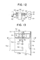
- Fig. 12 shows a modification 135' of the stop means 135.
- a sleeve 143 is mounted on a rear portion of a supporting member 136' to protrude therefrom, in which sleeve 143 a rod 137' having a worm wheel engaging portion 138' is slidably supported.
- a stop pin 141' is provided on a rear portion of the rod 137', which stop pin 141' is received in a long slot 144 in the sleeve 143.
- a recess 145 is formed in the rear end of the sleeve 143, which recess is spaced from the slot 144 by an angle of 90° around the axis of the sleeve 143.
- a first position of the device is again shown with solid lines and a second position with chain lines. '
- FIGs. 13 to 16 show details of the lower cover 75 and the sub-switch 151.
- the lower cover 75 is similar to that of the Fig. 3 apparatus to the extent that it is formed by a pair of semi-cylindrical covers, one a front cover 75a and the other a rear cover 75b, and is fixed to the supporting frame 52 through mounting means 76 associated with the rear cover 75b.
- the front cover 75a is attached to the rear cover 75b through hinges 152 so as to be openable as shown in Fig. 13 with chain lines and solid lines.
- the front cover 75a is lockable to the rear cover 75b in its closed position by a mechanism which is not shown in the drawings.
- An inward curved flange 153 (Fig.
- a knob 154 is provided for opening and closing the front cover 75a.
- a sub-switch 151 for example a limit switch or the like, is connected with the main switch 3 in series in the control circuit for the motor 55.
- the sub-switch 151 is secured via a mounting plate 155 to a lower portion of the upper frame 53 above an upper portion of a free end of the front cover 75a, and is provided with an actuating lever 156 which is biased toward an off position indicated by a chain line in Fig. 13.
- a lower end of the switch actuating lever 156 extends downward beyond the middle cover 74 through a hole 157 provided in the flange 81 thereof, to be engageable by the flange 153 of the front cover 75a.
- the sub-switch 151 is turned off when the front cover 75a is opened so as to bring the lever 156 to the position indicated by the chain line in Fig. 13.
- the motor 55 is not actuated even if the main switch 73 is turned on.
- the front cover 75a is closed, it is possible to actuate the motor 55 by turning on the main switch 73, since the sub-switch 151 is closed by the front cover 75a.
- the front cover 75a is first opened to place food on the cutting plate 63. At this time, there is no danger to the user even if he turns on the main switch 73 by mistake, because the sub-switch 151 is turned off by the opened front cover 75a. If the front cover 75a is opened by mistake during a cutting operation, since the sub-switch 151 is simultaneously turned off there is no danger to the user.
- the sub-switch 151 is provided above the free end of the front cover 75a. However, it is possible to locate the sub-switch in any position where its actuating lever 156 is moved to the on position when the front cover 75a is closed. In other words the location of sub-switch 151 is not restricted to that of the above described embodiment.
- Figs. 17A to 17C show details of the holding member 161.
- This member is formed by a base plate 162, a plurality of holding pins 163, and a cover 164.
- both the base plate 162 and the cover 164 are made of plastics, it is also possible to employ other suitable materials for them.
- the base plate 162 is formed with a plurality of small holes 165 in which holding pins 163 are inserted, and a threaded central hole 166 which is threadedly engaged with the main shaft 57.
- the cover 164 has a through-hole 168 for the passage of a threaded portion of the main shaft 57.
- the holding pins 163 are first inserted into the small holes 165 of the base plate 162, and then the cover 164 is fitted in the upper portion of the base plate 162. After that, the threaded portion 167 of the main shaft 57 is screwed into the threaded central hole 166 of the base plate 162, through the hole 168 of the cover 164, and fastened thereto. Disassembling of the holding member 161 can be performed in reverse sequence with respect to the above assembling sequence of the same. Since the holding member 161 can thus be easily assembled and disassembled, it is possible to wash all of its parts in a simple manner.
Landscapes
- Life Sciences & Earth Sciences (AREA)
- Engineering & Computer Science (AREA)
- Forests & Forestry (AREA)
- Mechanical Engineering (AREA)
- Chemical & Material Sciences (AREA)
- Food Science & Technology (AREA)
- Polymers & Plastics (AREA)
- Food-Manufacturing Devices (AREA)
- Nonmetal Cutting Devices (AREA)
Claims (5)
Applications Claiming Priority (6)
| Application Number | Priority Date | Filing Date | Title |
|---|---|---|---|
| JP111525/84 | 1984-07-23 | ||
| JP11152584U JPS6127079U (ja) | 1984-07-23 | 1984-07-23 | 氷削り機の主軸ロツク機構 |
| JP117481/84 | 1984-07-31 | ||
| JP1984117481U JPS6131698U (ja) | 1984-07-31 | 1984-07-31 | 食品切削装置における切削刃取付装置 |
| JP12825284U JPS6142296U (ja) | 1984-08-24 | 1984-08-24 | 食品切削装置 |
| JP128252/84 | 1984-08-24 |
Publications (2)
| Publication Number | Publication Date |
|---|---|
| EP0170459A1 EP0170459A1 (de) | 1986-02-05 |
| EP0170459B1 true EP0170459B1 (de) | 1990-10-03 |
Family
ID=27311984
Family Applications (1)
| Application Number | Title | Priority Date | Filing Date |
|---|---|---|---|
| EP85305013A Expired EP0170459B1 (de) | 1984-07-23 | 1985-07-12 | Lebensmittelschneidevorrichtung |
Country Status (9)
| Country | Link |
|---|---|
| EP (1) | EP0170459B1 (de) |
| KR (1) | KR900004281B1 (de) |
| AU (1) | AU548200B2 (de) |
| BR (1) | BR8406482A (de) |
| CA (1) | CA1233731A (de) |
| DE (1) | DE3579976D1 (de) |
| ES (1) | ES538610A0 (de) |
| GR (1) | GR81208B (de) |
| MX (1) | MX156687A (de) |
Cited By (2)
| Publication number | Priority date | Publication date | Assignee | Title |
|---|---|---|---|---|
| CN103406931A (zh) * | 2013-08-26 | 2013-11-27 | 东莞市飞新达精密机械科技有限公司 | 模切机的抬杠装置 |
| CN103406931B (zh) * | 2013-08-26 | 2016-11-30 | 广东飞新达智能设备股份有限公司 | 模切机的抬杠装置 |
Families Citing this family (2)
| Publication number | Priority date | Publication date | Assignee | Title |
|---|---|---|---|---|
| US4767068A (en) * | 1986-06-10 | 1988-08-30 | Chubu Industries, Inc. | Domestic ice shaver |
| CN114274587B (zh) * | 2021-11-30 | 2023-09-26 | 重庆皖渝纸制品有限公司 | 一种具有限位机构的纸箱加工用裁切装置 |
Family Cites Families (1)
| Publication number | Priority date | Publication date | Assignee | Title |
|---|---|---|---|---|
| US4055099A (en) * | 1975-02-28 | 1977-10-25 | Chubukoki Kabushiki Kaisha | Food slicer |
-
1984
- 1984-12-06 AU AU36358/84A patent/AU548200B2/en not_active Ceased
- 1984-12-07 GR GR81208A patent/GR81208B/el unknown
- 1984-12-14 ES ES84538610A patent/ES538610A0/es active Granted
- 1984-12-17 BR BR8406482A patent/BR8406482A/pt not_active IP Right Cessation
- 1984-12-24 KR KR1019840008297A patent/KR900004281B1/ko not_active Expired
- 1984-12-24 MX MX84203881A patent/MX156687A/es unknown
-
1985
- 1985-02-18 CA CA000474545A patent/CA1233731A/en not_active Expired
- 1985-07-12 DE DE8585305013T patent/DE3579976D1/de not_active Expired - Lifetime
- 1985-07-12 EP EP85305013A patent/EP0170459B1/de not_active Expired
Cited By (2)
| Publication number | Priority date | Publication date | Assignee | Title |
|---|---|---|---|---|
| CN103406931A (zh) * | 2013-08-26 | 2013-11-27 | 东莞市飞新达精密机械科技有限公司 | 模切机的抬杠装置 |
| CN103406931B (zh) * | 2013-08-26 | 2016-11-30 | 广东飞新达智能设备股份有限公司 | 模切机的抬杠装置 |
Also Published As
| Publication number | Publication date |
|---|---|
| ES8506996A1 (es) | 1985-08-16 |
| EP0170459A1 (de) | 1986-02-05 |
| CA1233731A (en) | 1988-03-08 |
| AU548200B2 (en) | 1985-11-28 |
| DE3579976D1 (de) | 1990-11-08 |
| ES538610A0 (es) | 1985-08-16 |
| GR81208B (en) | 1985-04-05 |
| MX156687A (es) | 1988-09-26 |
| BR8406482A (pt) | 1986-07-01 |
| KR900004281B1 (ko) | 1990-06-20 |
| KR860000847A (ko) | 1986-02-20 |
| AU3635884A (en) | 1985-11-28 |
Similar Documents
| Publication | Publication Date | Title |
|---|---|---|
| US7028930B2 (en) | Kitchen appliance with a safety interlock | |
| EP2677909B1 (de) | Lebensmittelverarbeitungsvorrichtung mit einem extern betätigten einstellmechanismus | |
| US4569266A (en) | Food-cutting apparatus | |
| CA1262126A (en) | Universal kitchen machine | |
| DE3650216T2 (de) | Rotierende Aufschnitt-Schneidvorrichtung für Nahrungsmittel. | |
| US5433144A (en) | Food processor with strainer and trash basket means | |
| EP0101237A2 (de) | Küchenmaschine | |
| US9049965B2 (en) | Food processing device with an externally operated adjustment mechanism | |
| US20060065134A1 (en) | Double blade peeling device for vegetables and fruits | |
| CA2804226C (en) | Food processor with external control for operating an adjustable cutting tool | |
| EP0170459A1 (de) | Lebensmittelschneidevorrichtung | |
| EP0116017B1 (de) | Elektrische Haushaltsmaschine zum Schneiden von Früchten, Gemüse und ähnlichen Nahrungsmitteln in kleine Stücke oder Klötze veränderbarer Dicke | |
| US7020970B1 (en) | Saw guard system | |
| EP0004987B1 (de) | Elektrischer Haushalts-Mischzerkleinerer | |
| KR950000269B1 (ko) | 가정용 아이스 쉐이버 | |
| US20190152086A1 (en) | Cutting Appliance | |
| CA1236380A (en) | Food slicer | |
| WO2021137263A1 (en) | Semi-automatic machine for crushing and for collecting outside frozen food substances for a subsequent food use of said food substances | |
| WO2001098042A2 (en) | Rotary cutter | |
| CN220024827U (zh) | 坚果开壳机 | |
| KR960003960Y1 (ko) | 세절기 | |
| JPH0620396Y2 (ja) | 食品クラツシヤ− | |
| JPS631789Y2 (de) | ||
| JPH0126354Y2 (de) | ||
| DE1268010B (de) | Schutzgehaeuse fuer Kreismesser einer Scheibenschneidmaschine |
Legal Events
| Date | Code | Title | Description |
|---|---|---|---|
| PUAI | Public reference made under article 153(3) epc to a published international application that has entered the european phase |
Free format text: ORIGINAL CODE: 0009012 |
|
| AK | Designated contracting states |
Designated state(s): DE FR GB IT |
|
| 17P | Request for examination filed |
Effective date: 19860422 |
|
| 17Q | First examination report despatched |
Effective date: 19870723 |
|
| GRAA | (expected) grant |
Free format text: ORIGINAL CODE: 0009210 |
|
| AK | Designated contracting states |
Kind code of ref document: B1 Designated state(s): DE FR GB IT |
|
| ITF | It: translation for a ep patent filed | ||
| REF | Corresponds to: |
Ref document number: 3579976 Country of ref document: DE Date of ref document: 19901108 |
|
| ET | Fr: translation filed | ||
| PLBE | No opposition filed within time limit |
Free format text: ORIGINAL CODE: 0009261 |
|
| STAA | Information on the status of an ep patent application or granted ep patent |
Free format text: STATUS: NO OPPOSITION FILED WITHIN TIME LIMIT |
|
| 26N | No opposition filed | ||
| ITTA | It: last paid annual fee | ||
| PGFP | Annual fee paid to national office [announced via postgrant information from national office to epo] |
Ref country code: GB Payment date: 19950706 Year of fee payment: 11 |
|
| PGFP | Annual fee paid to national office [announced via postgrant information from national office to epo] |
Ref country code: FR Payment date: 19950720 Year of fee payment: 11 |
|
| PGFP | Annual fee paid to national office [announced via postgrant information from national office to epo] |
Ref country code: DE Payment date: 19950731 Year of fee payment: 11 |
|
| PG25 | Lapsed in a contracting state [announced via postgrant information from national office to epo] |
Ref country code: GB Effective date: 19960712 |
|
| GBPC | Gb: european patent ceased through non-payment of renewal fee |
Effective date: 19960712 |
|
| PG25 | Lapsed in a contracting state [announced via postgrant information from national office to epo] |
Ref country code: FR Effective date: 19970328 |
|
| PG25 | Lapsed in a contracting state [announced via postgrant information from national office to epo] |
Ref country code: DE Effective date: 19970402 |
|
| REG | Reference to a national code |
Ref country code: FR Ref legal event code: ST |