EP0170476A2 - Datenübertragungsnetz - Google Patents
Datenübertragungsnetz Download PDFInfo
- Publication number
- EP0170476A2 EP0170476A2 EP85305172A EP85305172A EP0170476A2 EP 0170476 A2 EP0170476 A2 EP 0170476A2 EP 85305172 A EP85305172 A EP 85305172A EP 85305172 A EP85305172 A EP 85305172A EP 0170476 A2 EP0170476 A2 EP 0170476A2
- Authority
- EP
- European Patent Office
- Prior art keywords
- circuitry
- mode
- networking
- compatible
- network according
- Prior art date
- Legal status (The legal status is an assumption and is not a legal conclusion. Google has not performed a legal analysis and makes no representation as to the accuracy of the status listed.)
- Withdrawn
Links
- 238000004891 communication Methods 0.000 title claims abstract description 5
- 230000006855 networking Effects 0.000 claims abstract description 56
- 238000004804 winding Methods 0.000 claims description 23
- 230000005540 biological transmission Effects 0.000 claims description 21
- 101100172132 Mus musculus Eif3a gene Proteins 0.000 claims description 18
- 238000001514 detection method Methods 0.000 claims description 9
- 230000011664 signaling Effects 0.000 claims description 9
- 239000003990 capacitor Substances 0.000 claims description 8
- 238000006243 chemical reaction Methods 0.000 claims description 2
- 230000002401 inhibitory effect Effects 0.000 claims description 2
- 239000013307 optical fiber Substances 0.000 claims description 2
- 239000000872 buffer Substances 0.000 description 17
- 230000008878 coupling Effects 0.000 description 4
- 238000010168 coupling process Methods 0.000 description 4
- 238000005859 coupling reaction Methods 0.000 description 4
- 238000002955 isolation Methods 0.000 description 4
- 238000012935 Averaging Methods 0.000 description 2
- 238000010586 diagram Methods 0.000 description 2
- 206010000210 abortion Diseases 0.000 description 1
- 230000000903 blocking effect Effects 0.000 description 1
- 239000000835 fiber Substances 0.000 description 1
- 238000003780 insertion Methods 0.000 description 1
- 230000037431 insertion Effects 0.000 description 1
- 238000000034 method Methods 0.000 description 1
Images


Classifications
-
- H—ELECTRICITY
- H04—ELECTRIC COMMUNICATION TECHNIQUE
- H04L—TRANSMISSION OF DIGITAL INFORMATION, e.g. TELEGRAPHIC COMMUNICATION
- H04L12/00—Data switching networks
- H04L12/28—Data switching networks characterised by path configuration, e.g. LAN [Local Area Networks] or WAN [Wide Area Networks]
Definitions
- This invention relates to data communication networks.
- Such networks for example so-called local area networks, enable computers and other data handling devices to communicate.
- CSMA/CA CSMA/CA
- collision avoidance prevent collisions by allowing transmissions to occur only in accordance with a predetermined priority.
- a token ring network In one type of CSMA/CA network (called a token ring network) the devices are connected in a logical ring by twisted pair links between adjoining devices. A "token" signal passes around the ring and determines what unit may transmit at a given time, thus avoiding collisions.
- Another IEEE standard (802.5) applies to token ring networks.
- the aforesaid co-pending application discloses an 802.3 network organized into subnetworks with collisions being prevented by a collision avoidance technique within each subnetwork, and by a collision detection technique between subnetworks.
- a wiring concentrator connects a number of 802.3 devices to the common bus shared by all networks.
- the concentrator contains circuitry for carrying out the hybrid collision avoidance and collision detection mode of operation.
- the invention features a data communication networking system for carrying messages among a plurality of data handling devices in accordance with a plurality of different networking modes, each device being compatible with at least one of the networking modes, the networking system including networking circuitry for interconnecting the devices effectively in accordance with different ones of the networking modes, and concentrator circuitry having control circuitry for providing signals indicative of the networking modes with which different devices are compatible, and routing circuitry responsive to the control circuitry for routing messages between a given device and the networking circuitry in accordance with one of the networking modes with which the given device is compatible.
- the system includes a mode signaling circuit associated with at least one of the devices for delivering to the control circuitry mode information indicative of the networking modes with which the device is compatible; each device is connected to the concentrator circuitry by a message transmission path conforming to one of the networking modes with which the device is compatible for carrying messages to and from the device, and the mode signaling circuit associated with the device is connected to send the mode information via a mode information transmission path; there are lines connecting the concentrator circuitry and each device, and the lines serve simultaneously as parts of both the message transmission path and the mode information transmission path, and the paths have decoupling arrangements for decoupling the messages from the mode information; the lines include first and second pairs for carrying messages respectively to and from the device, the control circuitry, the lines, and the mode signaling circuit together comprise a pair of direct current circuits, the levels of direct current carried in the direct current circuits carries the mode information, and the direct current circuits comprise decoupling arrangements (transformers and a capacitor) for decoupling the direct current levels carried over the lines from signals which
- the networking circuitry when the fault signals are generated; there is fault indicator circuitry responsive to the fault circuitry for providing an alarm when the fault signals are generated; the fault circuitry includes deglitcher circuitry for inhibiting the fault circuitry from generating fault signals in response to preselected conditions; and the mode signaling circuit includes the conventional phantom circuits of a station interface unit compatible with IEEE standard 802.5.
- the control circuitry provides a signal to indicate that a device is compatible with the first mode, and provides no signal to indicate that a -device is compatible with the second mode, and the routing circuitry routes messages in accordance with the first mode in the absence of a signal from the control circuitry, and in accordance with the second mode when a signal is received from the control circuitry;
- the networking circuitry comprises separate networks corresponding respectively to different networking modes, and the routing circuitry comprises switch means for effectively connecting each device to a network corresponding to a networking mode with which the device is compatible;
- one networking mode comprises interconnecting the devices effectively in a ring, and the routing circuitry is responsive to the control circuitry for establishing a connection between each device which is compatible with said one networking mode, and each of the two adjacent devices in the ring;
- a second networking mode comprises a CSMA/CD arrangement having a plurality of subnetworks, the concentrator circuitry includes collision avoidance and detection circuitry for avoiding message collisions within each subnetwork and
- a single concentrator can be used to serve devices compatible with different networking modes automatically using signals generated by phantom circuitry already present in devices compatible with one of the networking modes.
- the two DC circuits each follow a path which includes a part of the split winding of each coupling transformer and one wire of each twisted pair, which maximizes the likelihood of detecting faults in the circuitry.
- the fault circuitry effectively and simply detects the faults, while the deglitcher minimizes the likelihood of erroneous fault signals.
- the token ring network automatically bypasses any faulty token ring device. When a token ring device is being served, the CSMA circuitry is inhibited to reduce the transmission of noise back through the concentrator to that device.
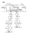
- wiring concentrators 10a, 10b and 10c are connected to each other by twisted- pair line 12 to form part of a first network operating in accordance with the IEEE 802.5 token ring standard, and are each also connected to coaxial bus 14 to form part of a second network operating in accordance with the IEEE 802.3 CSMA/CD standard.
- Illustrative user device 16 is connected to concentrator 10a by two twisted pair lines through standard CSMA/CD network interface unit (NIU) 18 and station interface unit (SIU) 20 (of the type disclosed in the copending application), for connecting device 16 in the CSMA/CD network in combined collision detect and collision avoidance operation, all as disclosed in detail in the copending application.
- NIU network interface unit
- SIU station interface unit
- Illustrative user device 22 is connected.by two twisted pair lines to the same concentrator 10a through standard 802.5 type SIU 24, for connecting device 22 in the token ring network.
- Wall plates 26, 28 are respectively connected to concentrator 10a by twisted pair lines 30, 32, and 34, 36 and permit SIU's 20, 24 respectively to plug into concentrator 10a via twisted pair lines 38, 40, and 42, 44.
- Concentrators 10b and 10c similarly support other groups of user devices.
- Each concentrator includes a number of identical routing and control circuits 39, each associated with one of the. user devices. Adjoining circuits 39 are linked by line 12.
- Each concentrator also has a circuit 51 which includes a transceiver and collision avoidance and detection circuitry, all as disclosed in detail in the copending application.
- Each circuit 39 is linked to circuit 51.
- twisted pair lines 42, 44 respectively connect to split windings 45, 46 of transformers 47, 48 for respectively carrying transmitted and received information packets between the SIU 24 and concentrator 10a.
- Windings 49, 50 of transformers 47, 48 respectively connect to a user device (not shown) for respectively carrying transmitted and received information packets between the SIU and the user device.
- Twisted pair line 34 connects to split winding 52 of transformer 54 in concentrator 10a (and also to twisted pair line 42 via wall plate 28).
- Winding 56 of transformer 54 (which is AC-coupled to split winding 52 to pass transmitted information packets) has two terminal wires 58a, 58b which respectively connect to relay armatures 60, 62.
- relay armatures 60, 62 In a first position (shown in Fig. 2), relay armatures 60, 62 connect line 34 to transmission line 64.
- the relay armatures 60, 62 In a second position (the opposite position from the one shown), the relay armatures 60, 62 connect line 34 to relay armatures 66, 67 which then also occupy a position opposite to the one shown and thus connect twisted pair line 34 to 802.5 token ring standard line 12.
- Twisted pair line 36 similarly connects to split winding 70 of transformer 72 (and also to twisted pair line 44 via wall plate 28).
- Winding 74 of transformer 72 (which is AC-coupled to split winding 70) has two terminal wires 76a, 76b which respectively connect to relay armatures 78, 80.
- relay armatures 78, 80 In a first position (shown), relay armatures 78, 80 connect line 36 to receive line 82.
- relay armatures 78, 80 In a second position (opposite to the one shown), relay armatures 78, 80 connect line 36 to relay armatures 84, 86 which then also occupy a position opposite the one shown and thus connect twisted pair line 36 of SIU 24 to IEEE 802.5 token ring standard line 12.
- Impedance matching resistors 87 are connected across the two leads of transmission line 64 and receive line 82.
- token ring standard line 12 is effectively connected to bypass the concentrator circuitry of Fig. 2 so that the associated SIU is excluded from the 802.5 network.
- Relay armatures 66, 67, 84, 86 are electromagnetically coupled to relay coil 89 so that relay armatures 66, 67, 84, 86 occupy the 802.3 position shown while a relay coil 89 is not energized, but occupy the 802.5 position (opposite to the one shown) when relay coil 89 is energized.
- Relay armatures 60, 62, 78, 80 likewise normally occupy the 802.3 position shown except when relay coil 91 is energized.
- Relay coils 89, 91 are powered respectively by relay drivers 92, 94 which are both connected to a trigger line 96.
- the signal on trigger line 961 determines whether relay armatures 60, 62, 66, 67, 78, 80, 84, 86 occupy the 802.3 or the 802.5 position, and thus determine whether information packets from an SIU are carried in the 802.5 or the 802.3 network.
- SIU 24 and concentrator 10a include circuitry which generates and carries DC signals from SIU 24 to concentrator 10a to indicate that it is an 802.5 device and causes concentrator 10a accordingly to connect SIU 24 into the 802.5 network.
- the DC signals sent from SIU 24 to concentrator l0a are carried over twisted pair lines 34, 36, 42, 44, which for this purpose are arranged to serve as parts of two separate DC paths.
- the DC signals originate in two standard phantom circuits 97, 98 already present in SIU 24.
- supply voltages +V BB and -V BB are delivered at points 99, 100.
- a logical low applied to input 101 e.g., by means of a voltage source controlled by a push button or by a switch which is automatically thrown by the insertion of lines 42, 44 into wallplate 28
- Inductor 103 carries the low level DC signal (while providing high frequency isolation) from transistor 102 to winding 46a of transformer 48.
- AC coupling capacitor 104 blocks the DC signal, forcing it to travel through one wire 106 of twisted pair line 44.
- Wire 107, in line 36 (connected to wire 106 in line 44), carries the current to winding 70b of transformer 72 in concentrator 10a.
- AC coupling capacitor 108 blocks the DC signal, forcing it into (and thereby enabling) opto coupler 109.
- the DC signal returns through winding 52a of transformer 54.
- Capacitor 110 blocks the DC signal, forcing it through one wire 111 of twisted pair line 34.
- Wire 112, in line 42 (connected to wire 111 in line 34), creates a path for the signal to return it to SIU 24.
- Winding 45b of transformer 47 passes the signal, blocked by capacitor 114 (like capacitors 104, 108, 110), through isolation inductor 116, thus completing one DC circuit.
- the logical low applied to input 101 effectively closes transistor switch 118 in phantom circuit 98.
- the resulting low level DC signal is carried in a second D C circuit made up of isolation inductor 120, winding 46b of transformer 48 (which cooperates with AC blocking capacitor 104), wire 121 of the twisted pair line 44, wire 122 in line 36, winding 70a of transformer 72, opto coupler 124, winding 52b of transformer 54, wire 126 of twisted pair line 34, wire 128 in line 42, winding 45a of ⁇ transformer 47, and isolation inductor 130.
- each DC circuit includes one side of the split winding of each of the transformers 47, 48, 54, 72, and one of the wires of each twisted pair 34, 36.
- the opto couplers 109, 124 isolate the 802.5 SIU 24 controller power supply 99, 100 from the concentrator 10a power supply 125, 126. Each opto coupler produces a logical low output signal when it is enabled. Each low signal respectively feeds into the inverting inputs of a logical AND gate 134. When both of its inputs are low (indicating that SIU 24 is a 802.5 type device), AND gate 134 outputs a logical high signal onto trigger line 96, which simultaneously triggers both relay drivers 92, 94 to power relay coils 89, 91, switching relay armatures 60, 62, 66, 67, 78, 80, 84, 86 to the 802.5 position.
- the outputs of opto couplers 109, 124 are also connected to circuitry 142 for sensing faults in the two DC circuits described above.
- an EXCLUSIVE OR gate 143 receives the output signals from the opto couplers and delivers a high output only if one of the opto coupler outputs is high and the other is low.
- the output of EXCLUSIVE OR gate 143 is connected both directly to an AND gate 144, and indirectly via two delaying buffers 145, 146 to the same AND gate 144.
- bypass relay driver 147 for driving a relay coil 148 which is electromagnetically coupled to relay armatures 149, 150 of bypass relay 151.
- Bypass relay armatures 149, 150 are normally in the position shown which allows information packets on the token ring network to pass between an 802.5 SIU and line 12.
- relay coil 148 is powered, armatures 149, 150 are switched to the opposite position, and connect lines 12 together via wires X, Y, thus bypassing faulty SIU 24.
- Fault line 152 is also connected via buffer 153 to an LED-type fault indicator (not shown).
- the circuit 51 of concentrator 10a includes CSMA/CD transceiver circuitry 200, collision avoidance circuitry 202, and receive drive circuitry 204, all as more fully illustrated and described in the copending application.
- Transmit line 64 and receive line 82 are respectively connected to the circuitry of Fig. 3.
- Trigger line 96 is connected to squelch 206 (for deactivating the squelch circuitry when a trigger signal appears on line 96), and via buffer 208 to the enabling input of receive buffer 210 (for disabling the receive buffer when a trigger signal appears on line 96), and via buffer 211 to the enabling input of collision gate 212 (for disabling the collision gate when a trigger signal appears on line 96).
- a transmitted message packet on line 64 is carried to buffer 222 (identical to other buffers, not shown) and activates squelch 206 (identical to other squelches, not shown), which sends a signal (S 1 ) via line 224 to PLA (programmable logic array) 226, and via gate 228 to collision gate 212 (which is enabled, thereby allowing collision signals, if any, to pass through it to SIU 24 via line 82), and to receive buffer 210 (which closes, thereby not allowing received packets onto line 82).
- Other identical collision gates and receive buffers serve other SIUs.
- PLA 226 If PLA 226 receives no other signal from other squelches, it sends an enabling signal (E l ) via line 230 (identical to lines 232, 234) to gate 236 (identical to other gates, not shown), which is enabled and allows the transmitted packet onto transmission bus 238, from which it propagates to standard transceiver circuitry 200 (e.g., circuitry such as that of Digital Equipment Corporation Model H-4000 Ethernet Transceiver), which has, in general, conventional circuitry (including an equalizer) to condition both transmitted and received packets, to limit the length of transmitted packets, and to sense collisions on bus 14. Transceiver 200 broadcasts the transmitted packet throughout the LAN for pickup by its addressee device.
- E l enabling signal
- a transmitted packet from SIU .24 arrives at concentrator 10a via line 64 just ahead of a transmitted packet from another SIU.
- the second packet activates a squelch (not shown) identical to squelch 206, which sends a signal (S 2 ) over line 240 that enables a collision gate (not shown) identical to collision gate 212, closes a receive buffer (not shown) identical to receive buffer 210 and reaches PLA 226 just after signal (S 1 ) does.
- PLA 226 senses that signal (S 1 ) was absolutely first, and sends a signal (E 1 ) via line 230 that enables gate 236 (permitting the first transmitted packet to pass to transmitter bus 238, and to transceiver 200 for broadcasting throughout the LAN).
- PLA 226 also sends a signal (C 2 ) via line 242 to demultiplexer (DMUX) 244, which sends a collision signal (generated by 10 MHz oscillator 246) via line 248 to a collision gate (not shown) identical to collision gate 212, through which it passes for transmission back to the NIU that had originated the second transmitted packet.
- This collision signal is "private"; that is, only the NIU that was the source of the second transmission receives it; whereupon the NIU withdraws the transmission.
- PLA 226 does not send a signal (E 2 ) to enable a gate (not shown) identical to gate 236, through which the second transmitted packet would have passed had it been absolutely first.
- received packets from any source in the LAN pass through the receiver circuitry of transceiver 200, through predistortion circuit 250 and buffer 252, and onto receiver bus 254, from which they move through each of receive buffers, e.g., receive buffer 210, to be read by appropriate addressees.
- Collisions on bus 14 between packets from separate subnetworks cause collision signals to be sent by each concentrator in the LAN to all SIUs, as distinguished from the "private" signalling for collision avoidance within a subnetwork, discussed above.
- the voltage level drops below the level when only one packet is on the line.
- a subcircuit within transceiver 200 monitors the voltage level and, whenever it detects such a drop, causes a collision signal to pass to all NIUs in the subnetwork, as follows.
- Low pass filter 260 which taps into the conventional receiver circuitry via line 259 and moves through DC voltage averaging circuit 262 to comparator 264, which also receives from trim pot 266 a standard signal whose voltage level is slightly lower (to compensate for noise on the line) than the voltage level on bus 14 when two packets are on it.
- comparator 264 Whenever comparator 264 in comparing the two voltage levels thus detects a collision on the bus, it sends an enabling signal over line 268 to gate 270 (connected also by line 272 to oscillator 246), which then opens to permit a 10 MHz collision signal from oscillator 246 to pass via line 274 to each of the collision gates, e.g., 212, through which it passes to all transmitting SIUs and NIUs, which withdraw their transmissions.
- gate 276 in the receiver circuit is connected to DC voltage averaging circuit 262 and is disabled when it detects a drop in voltage on bus 14, thus preventing received packets from passing from transceiver 200 to predistortion circuit 250.
- the system thus enables a single concentrator to serve devices compatible with different networking modes automatically using signals generated by phantom circuitry already present in devices compatible with one of the networking modes.
- the two DC circuits each follow a path which includes a part of the split winding of each coupling transformer and one wire of each twisted pair, which maximizes the likelihood of detecting faults in the circuitry.
- the fault circuitry effectively and simply detects the faults, while the deglitcher minimizes the likelihood of erroneous fault signals.
- the token ring network automatically bypasses any faulty token ring device. When a token ring device is being served, the CS MA circuitry is inhibited to reduce the transmission of noise back through the concentrator to that device.
- the deglitching circuitry detects the fault, sends a signal to the LED fault indicator, and throws the bypass relay which effectively connects line 12 to bypass the faulty SIU.
- line 12 could be replaced by a fiber optics cable 221 connected via an electro-optical converter 223 (both shown by dashed lines).
- the system can be extended to enable handling of more than two different-networking modes.
Landscapes
- Engineering & Computer Science (AREA)
- Computer Networks & Wireless Communication (AREA)
- Signal Processing (AREA)
- Small-Scale Networks (AREA)
- Data Exchanges In Wide-Area Networks (AREA)
- Use Of Switch Circuits For Exchanges And Methods Of Control Of Multiplex Exchanges (AREA)
Applications Claiming Priority (2)
| Application Number | Priority Date | Filing Date | Title |
|---|---|---|---|
| US63440084A | 1984-07-25 | 1984-07-25 | |
| US634400 | 1984-07-25 |
Publications (2)
| Publication Number | Publication Date |
|---|---|
| EP0170476A2 true EP0170476A2 (de) | 1986-02-05 |
| EP0170476A3 EP0170476A3 (de) | 1988-03-30 |
Family
ID=24543627
Family Applications (1)
| Application Number | Title | Priority Date | Filing Date |
|---|---|---|---|
| EP85305172A Withdrawn EP0170476A3 (de) | 1984-07-25 | 1985-07-19 | Datenübertragungsnetz |
Country Status (3)
| Country | Link |
|---|---|
| EP (1) | EP0170476A3 (de) |
| JP (1) | JPS6133046A (de) |
| CA (1) | CA1243761A (de) |
Cited By (1)
| Publication number | Priority date | Publication date | Assignee | Title |
|---|---|---|---|---|
| EP0567342A3 (de) * | 1992-04-24 | 1995-02-01 | Texas Instruments Inc | Signalschnittstelle zur Verbindung einer Netzeingangsschaltung mit einer Netzadapterschaltung. |
Families Citing this family (3)
| Publication number | Priority date | Publication date | Assignee | Title |
|---|---|---|---|---|
| JPS62263938A (ja) * | 1986-05-08 | 1987-11-16 | Kurita Water Ind Ltd | ニツケルイオンと亜鉛イオンとの分離方法 |
| FR2670925B1 (fr) * | 1990-12-20 | 1995-01-27 | Bull Sa | Architecture informatique distribuee utilisant un reseau local de type csma/cd. |
| CN114245242B (zh) * | 2021-12-23 | 2023-10-27 | 海南神州泰岳软件有限公司 | 一种用户下线检测方法、装置和电子设备 |
Family Cites Families (2)
| Publication number | Priority date | Publication date | Assignee | Title |
|---|---|---|---|---|
| IT1118355B (it) * | 1979-02-15 | 1986-02-24 | Cselt Centro Studi Lab Telecom | Sistema di interconnessione tra processori |
| DE3268099D1 (en) * | 1982-06-15 | 1986-02-06 | Ibm | Method and apparatus for controlling access to a communication network |
-
1985
- 1985-04-23 JP JP8734585A patent/JPS6133046A/ja active Pending
- 1985-05-07 CA CA000480886A patent/CA1243761A/en not_active Expired
- 1985-07-19 EP EP85305172A patent/EP0170476A3/de not_active Withdrawn
Cited By (1)
| Publication number | Priority date | Publication date | Assignee | Title |
|---|---|---|---|---|
| EP0567342A3 (de) * | 1992-04-24 | 1995-02-01 | Texas Instruments Inc | Signalschnittstelle zur Verbindung einer Netzeingangsschaltung mit einer Netzadapterschaltung. |
Also Published As
| Publication number | Publication date |
|---|---|
| CA1243761A (en) | 1988-10-25 |
| JPS6133046A (ja) | 1986-02-15 |
| EP0170476A3 (de) | 1988-03-30 |
Similar Documents
| Publication | Publication Date | Title |
|---|---|---|
| EP0161836B1 (de) | Datenübertragungsnetz | |
| US4935926A (en) | Networking circuitry | |
| AU600577B2 (en) | Lan communication system and medium adapter for use therewith | |
| AU687026B2 (en) | Method and apparatus for connecting nodes for a computer network | |
| EP0081335B1 (de) | Zugriffskontrolle für Übertragungsnetzwerke | |
| EP0103623B1 (de) | Mehrpunkt-datenübertragungssystem mit kollisionsermittlung | |
| EP0266151B1 (de) | Verfahren und Vorrichtung zur Verbindung von Rechnerarbeitsstationen | |
| KR100420708B1 (ko) | 토큰링 네트워크에서 사용되는 멀티포트 랜 스위치 | |
| EP0198932B1 (de) | Nebenanschlussanordnung und Verfahren zum Stationsanschliessen für ein Ringkommunikationssystem | |
| EP0946917A1 (de) | Elektronisches bussystem | |
| GB2166328A (en) | In-house distribution facility for a broadband communication system | |
| US4882728A (en) | Networking circuitry | |
| JPH10135987A (ja) | 通信ネットワークにおける入力信号伝送の制御方法及びそのためのコネクタとそこに内装される分離回路 | |
| US4887259A (en) | Communication network having multi-conjunction architecture | |
| US5530694A (en) | Device for connecting a station to a local area network comprising at least one ring | |
| EP0170476A2 (de) | Datenübertragungsnetz | |
| CN1886934B (zh) | 10/100 mbs网络设备 | |
| GB2218599A (en) | Local access network signel regenerator | |
| US6922742B2 (en) | Node device for a serial databus connecting a number of devices | |
| Schmidt et al. | Fibernet II: A fiber optic local area network with data collision sensing | |
| JPS6249739A (ja) | スタ−カプラ装置 | |
| Flewitt | Access mechanisms | |
| JPH04157839A (ja) | 回線分岐装置 | |
| JPH0514363A (ja) | ローカルエリアネツトワーク用トランシーバ | |
| JPH0695682B2 (ja) | 光データ伝送装置 |
Legal Events
| Date | Code | Title | Description |
|---|---|---|---|
| PUAI | Public reference made under article 153(3) epc to a published international application that has entered the european phase |
Free format text: ORIGINAL CODE: 0009012 |
|
| AK | Designated contracting states |
Designated state(s): AT BE CH DE FR GB IT LI LU NL SE |
|
| PUAL | Search report despatched |
Free format text: ORIGINAL CODE: 0009013 |
|
| AK | Designated contracting states |
Kind code of ref document: A3 Designated state(s): AT BE CH DE FR GB IT LI LU NL SE |
|
| 17P | Request for examination filed |
Effective date: 19880929 |
|
| 17Q | First examination report despatched |
Effective date: 19900710 |
|
| STAA | Information on the status of an ep patent application or granted ep patent |
Free format text: STATUS: THE APPLICATION HAS BEEN WITHDRAWN |
|
| 18W | Application withdrawn |
Withdrawal date: 19901120 |
|
| RIN1 | Information on inventor provided before grant (corrected) |
Inventor name: HERMAN, ALEXANDER |
|
| P01 | Opt-out of the competence of the unified patent court (upc) registered |
Effective date: 20230522 |