EP0170514A2 - Verfahren und Vorrichtung zur Ermittlung von magnetischen Kernresonanzspektren und darin verwendbare Spulen - Google Patents
Verfahren und Vorrichtung zur Ermittlung von magnetischen Kernresonanzspektren und darin verwendbare Spulen Download PDFInfo
- Publication number
- EP0170514A2 EP0170514A2 EP85305397A EP85305397A EP0170514A2 EP 0170514 A2 EP0170514 A2 EP 0170514A2 EP 85305397 A EP85305397 A EP 85305397A EP 85305397 A EP85305397 A EP 85305397A EP 0170514 A2 EP0170514 A2 EP 0170514A2
- Authority
- EP
- European Patent Office
- Prior art keywords
- coils
- coil
- sample
- transmission line
- switching means
- Prior art date
- Legal status (The legal status is an assumption and is not a legal conclusion. Google has not performed a legal analysis and makes no representation as to the accuracy of the status listed.)
- Granted
Links
Images


Classifications
-
- G—PHYSICS
- G01—MEASURING; TESTING
- G01R—MEASURING ELECTRIC VARIABLES; MEASURING MAGNETIC VARIABLES
- G01R33/00—Arrangements or instruments for measuring magnetic variables
- G01R33/20—Arrangements or instruments for measuring magnetic variables involving magnetic resonance
- G01R33/28—Details of apparatus provided for in groups G01R33/44 - G01R33/64
- G01R33/32—Excitation or detection systems, e.g. using radio frequency signals
- G01R33/34—Constructional details, e.g. resonators, specially adapted to MR
- G01R33/341—Constructional details, e.g. resonators, specially adapted to MR comprising surface coils
-
- G—PHYSICS
- G01—MEASURING; TESTING
- G01R—MEASURING ELECTRIC VARIABLES; MEASURING MAGNETIC VARIABLES
- G01R33/00—Arrangements or instruments for measuring magnetic variables
- G01R33/20—Arrangements or instruments for measuring magnetic variables involving magnetic resonance
- G01R33/28—Details of apparatus provided for in groups G01R33/44 - G01R33/64
- G01R33/32—Excitation or detection systems, e.g. using radio frequency signals
- G01R33/34—Constructional details, e.g. resonators, specially adapted to MR
- G01R33/34046—Volume type coils, e.g. bird-cage coils; Quadrature bird-cage coils; Circularly polarised coils
-
- G—PHYSICS
- G01—MEASURING; TESTING
- G01R—MEASURING ELECTRIC VARIABLES; MEASURING MAGNETIC VARIABLES
- G01R33/00—Arrangements or instruments for measuring magnetic variables
- G01R33/20—Arrangements or instruments for measuring magnetic variables involving magnetic resonance
- G01R33/28—Details of apparatus provided for in groups G01R33/44 - G01R33/64
- G01R33/32—Excitation or detection systems, e.g. using radio frequency signals
- G01R33/36—Electrical details, e.g. matching or coupling of the coil to the receiver
- G01R33/3628—Tuning/matching of the transmit/receive coil
-
- G—PHYSICS
- G01—MEASURING; TESTING
- G01R—MEASURING ELECTRIC VARIABLES; MEASURING MAGNETIC VARIABLES
- G01R33/00—Arrangements or instruments for measuring magnetic variables
- G01R33/20—Arrangements or instruments for measuring magnetic variables involving magnetic resonance
- G01R33/44—Arrangements or instruments for measuring magnetic variables involving magnetic resonance using nuclear magnetic resonance [NMR]
- G01R33/46—NMR spectroscopy
- G01R33/465—NMR spectroscopy applied to biological material, e.g. in vitro testing
-
- G—PHYSICS
- G01—MEASURING; TESTING
- G01R—MEASURING ELECTRIC VARIABLES; MEASURING MAGNETIC VARIABLES
- G01R33/00—Arrangements or instruments for measuring magnetic variables
- G01R33/20—Arrangements or instruments for measuring magnetic variables involving magnetic resonance
- G01R33/44—Arrangements or instruments for measuring magnetic variables involving magnetic resonance using nuclear magnetic resonance [NMR]
- G01R33/48—NMR imaging systems
- G01R33/483—NMR imaging systems with selection of signals or spectra from particular regions of the volume, e.g. in vivo spectroscopy
- G01R33/4831—NMR imaging systems with selection of signals or spectra from particular regions of the volume, e.g. in vivo spectroscopy using B1 gradients, e.g. rotating frame techniques, use of surface coils
Definitions
- This invention relates to nuclear magnetic resonance, and to coil assemblies for use in nuclear magnetic resonance.
- the signals obtained from the eight individual signal acquisitions carried out with the various combinations of these phase shifts are then averaged, and it is found that the signal obtained from various parts of the sensitive region of the receiving coil cancel, so that the actual signal sensed by the receiving coil is from a region localised in space.
- apparatus for obtaining an N.M.R. spectrum of a sample comprises means for generating a static magnetic field, a sample location space within the magnetic field for containing the sample, means for applying to the space an Rf field having a wavelength such as to cause perturbation of nuclear spins in the sample space in the presence of the magnetic field, and means for detecting the Rf signal induced in the sample as a consequence of the applied Rf field, the apparatus comprising at least two tuned Rf coils, at least one of the said Rf coils being connected to ground via switching means, whereby operation of the switching means causes the detuning of the said at least one coil. Either a transmit or receive coil, or both, or two or more receive or transmit coils, may be detuned by means of such a switching means.
- a further aspect of the invention provides a method of detuning a radiofrequency coil during a pulsed nuclear magnetic resonance procedure of sample analysis by operating a switch inserted between the radiofrequency coil and ground.
- the term "switch" is intended to encompass any means of substantially reducing the electrical current oscillating at the radiofrequency and flowing between the coil and ground.
- the invention may be utilised to minimise coupling either between a transmitter coil and a receiver coil, or between two transmitter coils. In either case, what is required is that, during the application of pulses with one coil, the other coil is detuned.
- a possible method of doing this in accordance with the invention is to use a switch in each Rf circuit within the RF probe.
- switching means are proving seween at least one of the coils and ground, to seme the said coil from the other coil. In practice inever the specification required of such a switch is very demanding. The switch must act aurkt, say in a few milliseconds, and must function in a strong magnetic field.
- the switching means takes the form of a swatch ar the end of a transmission line, for example a length of coaxial cable, having a length which is an integral number of quarter wavelengths (referred tu meinafterfter as a ⁇ /4 cable).
- a swatch ar the end of a transmission line, for example a length of coaxial cable, having a length which is an integral number of quarter wavelengths (referred tu meinafterfter as a ⁇ /4 cable).
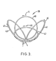
- a coil assembly for use in an N.M.R. spectrometer comprising at least two pairs of complimentary electrical coils, the coils being arranged in a non-coplanar "flower-petal" configuration, with coils corresponding to diametrically opposed petals connected together such that an electrical current applied thereto flows in the same direction about an axis passing through the said diametrically opposed coils.
- the number of pairs of coils is preferably 2, and these are preferably arranged symmetrically, ie. with their axes substantially at right angles to each other.
- the two coils of each pair are preferably also arranged to be at right angles. This configuration results in particularly advantageous localisation of the Rf field applied.
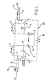
- FIG. 1 is a generalised circuit diagram of an Rf probe in accordance with the invention, incorporating two Rf transmit coils, 1 and 2, for providing the so-called ⁇ and ⁇ pulses, as referred in the publication by M.R. Bendall, referred to above.
- ⁇ coil 1 is provided with tuning capacitor 3, and matching capacitor 4.
- ⁇ coil 2 is provided with tuning capacitor 5, and matching capacitor 6.
- each of the coils 1 and 2 would be connected directly to earth at one end, as shown by the dotted lines 7 and 8.
- the direct earth connections 7 are omitted, and instead the coils 1 and 2 are connected respectively to co-axial cables 10 and 11.
- the coils 1 and 2 are connected to the central conductor of the co-axial cables, the outer screen being connected to earth.
- the length of the co-axial cables 10 and 11 corresponds to approximately 1 4 of the wavelength of the Rf frequency to be applied to the coils.
- Figure 9 represents a conventional NMR instrument, having a magnet with north and south pole-pieces 51 and 52.
- the magnet may be a permanent magnet, or, preferably, is a superconducting magnet.
- the tuning and matching capacitors shown in Figure 1 are contained within a screened probe assembly 56, illustrated by dotted line 56 in Figure 1.
- Connected to probe assembly 56 are the 0 coil 1, and ⁇ coil.
- Also terminating in probe assembly 56 are screened co-axial cables 10 and 11.
- switches 15 and 16 are provided between the central conductor and the screen of the co-axial cable.
- the switches 15 and 16 are, in practice, magnetic reed switches, and are operated at high speed by means of electrical coils 57 and 58 respectively.
- Electrical coils 57 and 58 are both driven by a computer, which also is responsible for producing the appropriate train of Rf pulses which are fed to the probe assembly.
- the Rf pulses are generated by an Rf generator 65 coupled to a Rf modulator 66. Modulation of the radio frequency signal produced by the Rf generator 65 is controlled by a pulse generator 68, in turn controlled by computer 55. The modulated Rf signal is amplified by an Rf amplifier 67, and from there is fed to the probe assembly 56 by means of a connection 54. As shown in Figure 1, probe assembly 56 contains the appropriate tuning and matching capacitors to enable both coils 1 and 2 to be separately tuned and matched.
- An Rf receiver 74 of conventional form is also connected to the probe assembly 56, and receives the radio frequency signal resulting from the applied pulse sequence.
- the receiving antenna for the Rf receiver 74 may be one of the coils 1 or 2, or, is a further coil included in the probe assembly.
- the signal from the Rf receiver 74 is also passed to computer 55, where it is analysed by appropriate means, to provide the desired NMR signal.
- a sample support 69 is provided to support the sample in the magnetic field. For example, if the apparatus is intended for carrying out an NMR experiment on a human body, the sample support 69 may be adapted to support a human patient with the appropriate part of the body between the pole pieces 51 and 52.
- the switches 15 and 16 are spaced from the main spectrometer field by a distance corresponding to the length of the co-axial cables 10 and 11 (typically 1.5m in the experiments described), no substantial interference by the switching coils with the main spectrometer field coil is experienced.
- the circuit is equivalent to direct connections between the coils 1 and 2, and earth.
- the high speed switches 15 and 16 are in the closed position, they are equivalent to the breaking of the connection between the coils 1 and 2 and earth.
- the switches 15 and 16 and associated coils may be included within a magnetically shielded enclosure, for example a steel or mu-metal box.
- the point of insertion of the ⁇ /4 cable into the Rf circuit is critical. If inserted between the live Rf input and the matching capacitor (point a of Fig. 1), the Rf circuit is dematched when the relay is closed, rather than detuned, and the Rf coil would still couple with an adjacent coil. If inserted in the high voltage part of the circuit (point b of Fig. 1) the Q of the coil is dramatically decreased and the ⁇ /4 cable or the relays would be likely to fail under pulse power.
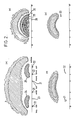
- FIGS 2a to 2d are schematic diagrams , illustrating the intensity contours of signals obtained from a homogeneous sample (a 9mm thick slice phantom), using a circuit as in Figure 1.
- Two transmit coils 21 and 22 were utilised in a co-planar arrangement, the outer having a diameter of 70mm, and the inner a diameter of 20mm. In this arrangement, if not for the circuitry described above, the coils would be closely coupled. For example, having tuned and matched one coil to 32 MHz, it is impossible to introduce a second coil and tune and match it to 32 MHz. However, using the two ⁇ /4 cables, and high speed switches, the interaction between the two coils is virtually eliminated.
- Figure 2a represents the intensity contours obtained with pulse power applied using the large coil 22 only, with the small coil 21 detuned.
- the x-direction is taken to be the depth axis or coil axis.
- the smaller cross-hatched regions 24 and 25 of Figure 2 (a) correspond to e angles close to 270° ("the 270° region").
- the image is slightly distorted, curving away from the surface, as a result of magnetic field inhomogeneity.
- Figure 2b represents a similar contour diagram of the sensitive volume produced in the small coil 21, with the large coil 22 detuned.
- the complicated area close to the surface is the high flux region. At least a 270°, 450 and 630° signal regions can be discerned (30, 29 and 28 respectively).
- Figure 2c represents the image of the sensitive volume in the xy plane, which is produced for the same coil arrangement and sample, using a pulse sequence of the form [A]. acquire with e coil
- Figure 2(d) is the image of the sensitive volume in the xz plane of the same sequence.
- the detune switches 15 and 16 were not completely equivalent to opening the Rf circuits, as they shifted the tuning points to two points an equal distance either side of 32 MHz, (ie.to +8 MHz and +12 MHz for the large and small coil respectively).
- the switches 15 and 16 lowered the Q's of both coils by 40%, compared with the Q's measured for each coil when the detuned switches and the other coil is entirely removed from the probe.
- Cables external to an Rf probe can easily feed in external noise. This was prevented by optically coupling the external spectrometer pulse line to the reed relays and using a common earth for the ⁇ /4 cables and the Faraday shielding around the Rf coils.
- the reed relays employed (RS Components, Corby, England, type 7-RSR-A, operate time 2 msec maximum, release time 0.2 msec, breakdown voltage minimum 700 V d.c.) arced under Rf power for pulses longer than 1 msec, for a large range of Rf power levels. For the experiments carried out, this was not a problem, thought it was determined that the arcing could be eliminated by inserting short delays (eg. 1 msec) between long pulses.
- the sensitive volume was image at 31 P frequencies using a slice phantom of H 3 PO 4 and a standard procedure which, for a single coil, may be written schematically as The y (or z) gradient after the first pulse is adjusted to ensure that the top of the spin-echo occurs at the end of the second T period halfway through signal acquisition.
- the incremented x gradient provides the second image dimension via a second transformation, ie. the standard Fourier Transform imaging method.
- the receive coil for these experiments was a broad-band coil 23.
- FIG. 3 A suitable coil arrangement is illustrated in Figure 3, which comprises four loops, 40, 41, 42 and 43.
- the loops are connected at their base, so that the circuit is continuous, and so that for each pair of opposite loops, electric current flows in the same direction (ie. in the same direction about an axis passing through the pairs of opposite loops).
- the current in loops 40, 41, 42 and 43 flows in the direction shown by arrows 44, 45, 46 and 47 respectively.
- the opposite coils 40 and 42 are mutually at right angles, as are opposite coils 41 and 43.
- an axis drawn through the centre of coils 41 and 43 intersects an axis drawn through the centre of coils 40 and 42 at right angles.
- the coil assembly is utilised as the ⁇ coil for a spectrometer probe as described above.
- the ⁇ probe is disposed in a plane perpendicular to an axis passing through the "stem" of the flower.
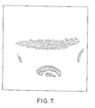
- Figures 4 and 7 show 31p images of sensitive volume using a lcm thick circular slice phantom of H 3 P0 4 of sufficient diameter to fit just inside the four coils 40, 41, 42, 43, whose diameters were 9cm.
- the images were obtained using the depth pulse scheme using the terminology referred to above, modified by inserting pulsed field gradients before and after the last 2 ⁇ pulse in the same way that scheme [A] was modified using the general method shown in scheme [B].
- Figure 4 is a contour diagram obtained for the slice phantom placed in the middle of the coil array in the xy plane, and Figure 5 shows the equivalent image in the xz plane.
- Figures 6 and 7 show images for the two planes which contain the x axis, and are diagonal to y and z. Departure from symmetry (eg. as in Figure 5) is thought to result from a failure to wind the coils 40 to 43 with perfect symmetry.
- Figure 8 shows the 31p images of the sensitive volume obtained for the circular slice phantom in the xy plane using the pulse scheme [A], modified to include the general method in [B].
- the coil assembly 39 was used as the ⁇ coil, and an additional surface coil as ⁇ coil.
- Such an arrangement would be suitable, for example, for performing NMR determinations on the human brain, without detecting the intervening skull.
- the apparatus and method according to the invention may also be utilised on other parts of the human body.
- apparatus for obtaining a spectrum of a living body comprising means for producing a homogeneous magnetic field, and a pair of Rf coils, switching means associated with each of the Rf coils for connecting the coil to ground, whereby each of the said coils may be detuned, means for applying a sequence of pulses to at least one of the coils, and for operating the switching means in association therewith, to selectively detune one or other of the said coils.
- the apparatus according to the invention may preferably include a sample support, for example a support for a patient, to support the patient with a part of the body of the patient in the magnetic field.
- the opposed coils of the "flower petal" configuration are right angles to each other, angles greater than or less than a right angle maybe utilised.
- all four coils constituting the "petals” are wired in series, it would be possible for the two pairs of coils to be used separately as the ⁇ and coils respectively.
- the current in diametrically opposed coils should flow in the same direction (i.e. in the same direction about an axis passing through the coils), in certain circumstances, for example when one pair of coils is used as the ⁇ set, and one as the ⁇ , it may be advantageous to arrange for the current to flow in opposite directions in opposed coils.
Landscapes
- Physics & Mathematics (AREA)
- Condensed Matter Physics & Semiconductors (AREA)
- General Physics & Mathematics (AREA)
- Spectroscopy & Molecular Physics (AREA)
- High Energy & Nuclear Physics (AREA)
- Health & Medical Sciences (AREA)
- Life Sciences & Earth Sciences (AREA)
- General Health & Medical Sciences (AREA)
- Molecular Biology (AREA)
- Optics & Photonics (AREA)
- Magnetic Resonance Imaging Apparatus (AREA)
Applications Claiming Priority (4)
| Application Number | Priority Date | Filing Date | Title |
|---|---|---|---|
| GB848419466A GB8419466D0 (en) | 1984-07-31 | 1984-07-31 | Obtaining nmr spectra and coils |
| GB8419466 | 1984-07-31 | ||
| GB858514852A GB8514852D0 (en) | 1984-07-31 | 1985-06-12 | Apparatus for obtaining n m r spectra & coils |
| GB8514852 | 1985-06-12 |
Publications (3)
| Publication Number | Publication Date |
|---|---|
| EP0170514A2 true EP0170514A2 (de) | 1986-02-05 |
| EP0170514A3 EP0170514A3 (en) | 1987-09-02 |
| EP0170514B1 EP0170514B1 (de) | 1990-09-19 |
Family
ID=26288046
Family Applications (1)
| Application Number | Title | Priority Date | Filing Date |
|---|---|---|---|
| EP85305397A Expired - Lifetime EP0170514B1 (de) | 1984-07-31 | 1985-07-29 | Verfahren und Vorrichtung zur Ermittlung von magnetischen Kernresonanzspektren und darin verwendbare Spulen |
Country Status (3)
| Country | Link |
|---|---|
| US (1) | US4728896A (de) |
| EP (1) | EP0170514B1 (de) |
| DE (1) | DE3579773D1 (de) |
Cited By (10)
| Publication number | Priority date | Publication date | Assignee | Title |
|---|---|---|---|---|
| EP0262495A1 (de) * | 1986-09-22 | 1988-04-06 | Siemens Aktiengesellschaft | Kernspin-Resonanzgerät zur Ermittlung von Spektren oder Bildern eines Untersuchungsobjektes |
| DE3743105A1 (de) * | 1986-12-19 | 1988-07-07 | Toshiba Kawasaki Kk | Sende/empfangssystem fuer magnetresonanz-abbildungssystem |
| EP0256520A3 (en) * | 1986-08-15 | 1988-07-20 | Mcw Research Foundation, Inc. | Nmr local coil network |
| EP0257782A3 (de) * | 1986-08-07 | 1989-09-20 | Picker International, Inc. | Gerät zur magnetischen Resonanz |
| EP0312586A4 (en) * | 1987-04-30 | 1990-10-24 | Varian Associates, Inc. | Spurious resonance control for nmr observe coils |
| EP0335512A3 (de) * | 1988-03-31 | 1990-12-19 | Varian Associates, Inc. | Kalibrierte Entkopplung von konzentrischen Oberflächenspulen mit starker Kopplung |
| EP0322192A3 (en) * | 1987-12-21 | 1990-12-27 | General Electric Company | Apparatus for dynamically disabling an nmr field coil |
| EP0325351B1 (de) * | 1988-01-19 | 1995-05-17 | The Regents Of The University Of California | Schaltbare Vielfachanordnung von Hochfrequenzspulen mit verschiedenen und überlappenden Blickfeldern der einzelnen Spulen zur Bilderzeugung mittels magnetischer Resonanz |
| EP0347180B1 (de) * | 1988-06-15 | 1997-09-03 | Btg International Limited | Elektrische Oberflächenspulenanordnungen |
| AT517551B1 (de) * | 2015-07-30 | 2018-12-15 | Univ Graz Tech | Messvorrichtung zur breitbandigen Anregung und Erfassung von NQR- und/oder NMR-Spektrographie-Signalen |
Families Citing this family (15)
| Publication number | Priority date | Publication date | Assignee | Title |
|---|---|---|---|---|
| US4839594A (en) * | 1987-08-17 | 1989-06-13 | Picker International, Inc. | Faraday shield localized coil for magnetic resonance imaging |
| US4783629A (en) * | 1987-10-07 | 1988-11-08 | The Regents Of The University Of California | RF coil for MRI with self-tracking ganged coupling capacitors |
| US4825162A (en) * | 1987-12-07 | 1989-04-25 | General Electric Company | Nuclear magnetic resonance (NMR) imaging with multiple surface coils |
| DE4002160A1 (de) * | 1990-01-25 | 1991-08-08 | Bruker Analytische Messtechnik | Probenkopf fuer kernresonanzmessungen und verfahren zur messung von kernresonanzen |
| US5138260A (en) * | 1990-11-21 | 1992-08-11 | Picker International, Inc. | Computer controlled switching of multiple rf coils |
| US5621323A (en) * | 1991-11-29 | 1997-04-15 | Magnetic Research, Inc. | Surface coil elements |
| US5357958A (en) * | 1993-03-18 | 1994-10-25 | The Regents Of The University Of California | Interventional MRI system and RF coils therefore |
| DE4324021C2 (de) * | 1993-07-17 | 1996-05-30 | Bruker Analytische Messtechnik | Therapietomograph |
| US5663645A (en) * | 1994-08-02 | 1997-09-02 | Toshiba America Mri Inc. | Spatially orthogonal rectangular coil pair suitable for vertical magnetic field MRI system |
| US6489872B1 (en) | 1999-05-06 | 2002-12-03 | New Mexico Resonance | Unilateral magnet having a remote uniform field region for nuclear magnetic resonance |
| GB2427479B (en) * | 2005-06-22 | 2007-11-14 | Siemens Magnet Technology Ltd | Particle Radiation Therapy Equipment and method for performing particle radiation therapy |
| JP5357010B2 (ja) * | 2006-04-24 | 2013-12-04 | コーニンクレッカ フィリップス エヌ ヴェ | コイルシステム及び磁気共鳴システム |
| JP5117747B2 (ja) * | 2007-03-23 | 2013-01-16 | ジーイー・メディカル・システムズ・グローバル・テクノロジー・カンパニー・エルエルシー | Rfコイルおよび磁気共鳴イメージング装置 |
| CN107356892B (zh) * | 2017-07-05 | 2019-12-03 | 上海联影医疗科技有限公司 | 一种磁共振射频线圈调节方法、磁共振扫描系统及介质 |
| US20250076426A1 (en) * | 2022-01-06 | 2025-03-06 | The Regents Of The University Of California | Flexible Radiofrequency (RF) Coil for Small Field-of-View Magnetic Resonance Imaging (MRI) |
Family Cites Families (10)
| Publication number | Priority date | Publication date | Assignee | Title |
|---|---|---|---|---|
| CA655029A (en) * | 1963-01-01 | Varian Associates | Gyromagnetic resonance methods and apparatus | |
| GB1275902A (en) * | 1968-08-09 | 1972-06-01 | Perkin Elmer Ltd | Nuclear magnetic resonance probe |
| DE2736744A1 (de) * | 1976-04-26 | 1979-02-22 | Hiss Eckart | Vielfachspule fuer naeherungsschalter |
| US4093911A (en) * | 1977-02-22 | 1978-06-06 | Varian Associates, Inc. | Nuclear magnetic resonance spectrometer employing an improved resonance signal gating circuit |
| US4408162A (en) * | 1980-12-22 | 1983-10-04 | Varian Associates, Inc. | Sensitivity NMR probe |
| DE3131946A1 (de) * | 1981-08-12 | 1983-03-17 | Siemens AG, 1000 Berlin und 8000 München | "hochfrequenz-magnetsystem in einer einrichtung der kernspinresonanz-technik" |
| US4590427A (en) * | 1983-03-28 | 1986-05-20 | The United States Of America As Represented By The United States Department Of Energy | Nuclear magnetic resonance apparatus having semitoroidal rf coil for use in topical NMR and NMR imaging |
| US4641097A (en) * | 1984-05-10 | 1987-02-03 | General Electrtic Company | Elliptical cross-section slotted-tube radio-frequency resonator for nuclear magnetic resonance imaging |
| US4629988A (en) * | 1984-07-02 | 1986-12-16 | General Electric Company | Method of imaging by depth-resolved surface coil spectroscopy |
| US4620155A (en) * | 1984-08-16 | 1986-10-28 | General Electric Company | Nuclear magnetic resonance imaging antenna subsystem having a plurality of non-orthogonal surface coils |
-
1985
- 1985-07-29 EP EP85305397A patent/EP0170514B1/de not_active Expired - Lifetime
- 1985-07-29 DE DE8585305397T patent/DE3579773D1/de not_active Expired - Lifetime
- 1985-07-29 US US06/759,881 patent/US4728896A/en not_active Expired - Lifetime
Cited By (11)
| Publication number | Priority date | Publication date | Assignee | Title |
|---|---|---|---|---|
| EP0257782A3 (de) * | 1986-08-07 | 1989-09-20 | Picker International, Inc. | Gerät zur magnetischen Resonanz |
| EP0256520A3 (en) * | 1986-08-15 | 1988-07-20 | Mcw Research Foundation, Inc. | Nmr local coil network |
| EP0262495A1 (de) * | 1986-09-22 | 1988-04-06 | Siemens Aktiengesellschaft | Kernspin-Resonanzgerät zur Ermittlung von Spektren oder Bildern eines Untersuchungsobjektes |
| US4801885A (en) * | 1986-09-22 | 1989-01-31 | Siemens Aktiengesellshaft | Nuclear magnetic resonance apparatus for the identification of spectra or images of an examination subject |
| DE3743105A1 (de) * | 1986-12-19 | 1988-07-07 | Toshiba Kawasaki Kk | Sende/empfangssystem fuer magnetresonanz-abbildungssystem |
| EP0312586A4 (en) * | 1987-04-30 | 1990-10-24 | Varian Associates, Inc. | Spurious resonance control for nmr observe coils |
| EP0322192A3 (en) * | 1987-12-21 | 1990-12-27 | General Electric Company | Apparatus for dynamically disabling an nmr field coil |
| EP0325351B1 (de) * | 1988-01-19 | 1995-05-17 | The Regents Of The University Of California | Schaltbare Vielfachanordnung von Hochfrequenzspulen mit verschiedenen und überlappenden Blickfeldern der einzelnen Spulen zur Bilderzeugung mittels magnetischer Resonanz |
| EP0335512A3 (de) * | 1988-03-31 | 1990-12-19 | Varian Associates, Inc. | Kalibrierte Entkopplung von konzentrischen Oberflächenspulen mit starker Kopplung |
| EP0347180B1 (de) * | 1988-06-15 | 1997-09-03 | Btg International Limited | Elektrische Oberflächenspulenanordnungen |
| AT517551B1 (de) * | 2015-07-30 | 2018-12-15 | Univ Graz Tech | Messvorrichtung zur breitbandigen Anregung und Erfassung von NQR- und/oder NMR-Spektrographie-Signalen |
Also Published As
| Publication number | Publication date |
|---|---|
| EP0170514B1 (de) | 1990-09-19 |
| EP0170514A3 (en) | 1987-09-02 |
| US4728896A (en) | 1988-03-01 |
| DE3579773D1 (de) | 1990-10-25 |
Similar Documents
| Publication | Publication Date | Title |
|---|---|---|
| EP0170514B1 (de) | Verfahren und Vorrichtung zur Ermittlung von magnetischen Kernresonanzspektren und darin verwendbare Spulen | |
| EP0359374B1 (de) | Kernspinresonanzgerät | |
| EP1059539B1 (de) | RF-Körperspule für ein offenes System zur Bilderzeugung mittels magnetischer Resonanz | |
| CA2311630C (en) | Mri in cylindrical coordinates using a catheter antenna | |
| EP0201084B1 (de) | Lokale Sonde zur Anwendung bei der Bilderzeugung mittels magnetischer Kernresonanz | |
| JP3872431B2 (ja) | 磁気共鳴イメージング装置 | |
| EP0580327B1 (de) | Apparat mittels magnetischer Resonanz | |
| EP0254983B1 (de) | Polarisationstransfer durch selektive Homonukleartechnik zur Unterdrückung von entkoppelten Spins in der KMR-Spektroskopie | |
| US20030184293A1 (en) | Multiple channel, microstrip transceiver volume array for magnetic resonance imaging | |
| US8406852B2 (en) | MRI involving forwardly and reversely polarised RF excitation | |
| EP1336114A1 (de) | Vorrichtung zur bildgebung mittels magnetischer resonanz in externen statischen magnetfeldern | |
| US4385277A (en) | Topical nuclear magnetic resonance spectrometer and method | |
| EP0335512A2 (de) | Kalibrierte Entkopplung von konzentrischen Oberflächenspulen mit starker Kopplung | |
| EP0302742B1 (de) | Verfahren zur Darstellung der Verteilung von paramagnetischen Molekülen in einem Lösungsmittel | |
| EP0955554A2 (de) | Mehrfrequenz-Magnetresonanzbildgebung | |
| GB2261516A (en) | Magnetic resonance system and probe | |
| EP0349894A2 (de) | Zweidimensionales Verfahren zur Spektralzuordnung von Kernresonanzsignalen von Metaboliten mit gekoppelten Kernen | |
| EP1241485B1 (de) | Kernspinresonanz mit Overhauserverstärkung | |
| EP0460929A2 (de) | NMR Spektroskopie | |
| EP0797102B1 (de) | Ein Gerät zur Anregung und zum Erfassen von magnetischer Resonanz | |
| Klomp et al. | Radio-frequency probe for 1H decoupled 31P MRS of the head and neck region | |
| US5055792A (en) | Miniaturized surface probes | |
| US20060232272A1 (en) | Imaging apparatus and method | |
| EP0845108B1 (de) | Bilderzeugung mittels magnetischer resonanz | |
| Rubinson et al. | NMR imaging with shorted coaxial line probes |
Legal Events
| Date | Code | Title | Description |
|---|---|---|---|
| PUAI | Public reference made under article 153(3) epc to a published international application that has entered the european phase |
Free format text: ORIGINAL CODE: 0009012 |
|
| AK | Designated contracting states |
Designated state(s): CH DE FR GB LI NL |
|
| PUAL | Search report despatched |
Free format text: ORIGINAL CODE: 0009013 |
|
| AK | Designated contracting states |
Kind code of ref document: A3 Designated state(s): CH DE FR GB LI NL |
|
| 17P | Request for examination filed |
Effective date: 19871214 |
|
| 17Q | First examination report despatched |
Effective date: 19890606 |
|
| GRAA | (expected) grant |
Free format text: ORIGINAL CODE: 0009210 |
|
| AK | Designated contracting states |
Kind code of ref document: B1 Designated state(s): CH DE FR GB LI NL |
|
| REF | Corresponds to: |
Ref document number: 3579773 Country of ref document: DE Date of ref document: 19901025 |
|
| ET | Fr: translation filed | ||
| PLBE | No opposition filed within time limit |
Free format text: ORIGINAL CODE: 0009261 |
|
| STAA | Information on the status of an ep patent application or granted ep patent |
Free format text: STATUS: NO OPPOSITION FILED WITHIN TIME LIMIT |
|
| 26N | No opposition filed | ||
| PGFP | Annual fee paid to national office [announced via postgrant information from national office to epo] |
Ref country code: NL Payment date: 20010731 Year of fee payment: 17 Ref country code: FR Payment date: 20010731 Year of fee payment: 17 |
|
| PGFP | Annual fee paid to national office [announced via postgrant information from national office to epo] |
Ref country code: CH Payment date: 20011025 Year of fee payment: 17 |
|
| REG | Reference to a national code |
Ref country code: GB Ref legal event code: IF02 |
|
| PG25 | Lapsed in a contracting state [announced via postgrant information from national office to epo] |
Ref country code: LI Free format text: LAPSE BECAUSE OF NON-PAYMENT OF DUE FEES Effective date: 20020731 Ref country code: CH Free format text: LAPSE BECAUSE OF NON-PAYMENT OF DUE FEES Effective date: 20020731 |
|
| PGFP | Annual fee paid to national office [announced via postgrant information from national office to epo] |
Ref country code: DE Payment date: 20021106 Year of fee payment: 18 |
|
| PG25 | Lapsed in a contracting state [announced via postgrant information from national office to epo] |
Ref country code: NL Free format text: LAPSE BECAUSE OF NON-PAYMENT OF DUE FEES Effective date: 20030201 |
|
| REG | Reference to a national code |
Ref country code: CH Ref legal event code: PL |
|
| PG25 | Lapsed in a contracting state [announced via postgrant information from national office to epo] |
Ref country code: FR Free format text: LAPSE BECAUSE OF NON-PAYMENT OF DUE FEES Effective date: 20030331 |
|
| NLV4 | Nl: lapsed or anulled due to non-payment of the annual fee |
Effective date: 20030201 |
|
| REG | Reference to a national code |
Ref country code: FR Ref legal event code: ST |
|
| PG25 | Lapsed in a contracting state [announced via postgrant information from national office to epo] |
Ref country code: DE Free format text: LAPSE BECAUSE OF NON-PAYMENT OF DUE FEES Effective date: 20040203 |
|
| PGFP | Annual fee paid to national office [announced via postgrant information from national office to epo] |
Ref country code: GB Payment date: 20040719 Year of fee payment: 20 |
|
| PG25 | Lapsed in a contracting state [announced via postgrant information from national office to epo] |
Ref country code: GB Free format text: LAPSE BECAUSE OF EXPIRATION OF PROTECTION Effective date: 20050728 |
|
| REG | Reference to a national code |
Ref country code: GB Ref legal event code: PE20 |