EP0170532B1 - Unsichtbare Befestigung von einem hierzugefügten Teil auf einem Träger - Google Patents
Unsichtbare Befestigung von einem hierzugefügten Teil auf einem Träger Download PDFInfo
- Publication number
- EP0170532B1 EP0170532B1 EP19850400812 EP85400812A EP0170532B1 EP 0170532 B1 EP0170532 B1 EP 0170532B1 EP 19850400812 EP19850400812 EP 19850400812 EP 85400812 A EP85400812 A EP 85400812A EP 0170532 B1 EP0170532 B1 EP 0170532B1
- Authority
- EP
- European Patent Office
- Prior art keywords
- support
- blade
- anchoring
- pion
- seating
- Prior art date
- Legal status (The legal status is an assumption and is not a legal conclusion. Google has not performed a legal analysis and makes no representation as to the accuracy of the status listed.)
- Expired
Links
- 238000004873 anchoring Methods 0.000 claims description 5
- 241000920340 Pion Species 0.000 claims 3
- 238000003032 molecular docking Methods 0.000 description 1
Images
Classifications
-
- F—MECHANICAL ENGINEERING; LIGHTING; HEATING; WEAPONS; BLASTING
- F16—ENGINEERING ELEMENTS AND UNITS; GENERAL MEASURES FOR PRODUCING AND MAINTAINING EFFECTIVE FUNCTIONING OF MACHINES OR INSTALLATIONS; THERMAL INSULATION IN GENERAL
- F16B—DEVICES FOR FASTENING OR SECURING CONSTRUCTIONAL ELEMENTS OR MACHINE PARTS TOGETHER, e.g. NAILS, BOLTS, CIRCLIPS, CLAMPS, CLIPS OR WEDGES; JOINTS OR JOINTING
- F16B5/00—Joining sheets or plates, e.g. panels, to one another or to strips or bars parallel to them
- F16B5/12—Fastening strips or bars to sheets or plates, e.g. rubber strips, decorative strips for motor vehicles, by means of clips
- F16B5/123—Auxiliary fasteners specially designed for this purpose
- F16B5/125—Auxiliary fasteners specially designed for this purpose one of the auxiliary fasteners is comprising wire or sheet material or is made thereof
Definitions
- Document FR-A- 1 394 502 describes an element intended to be fixed on a support by means of an elastic member coupled to said element and capable of being hooked to an anchoring pin secured to the support, the attachment zone. from the elastic member to the anchor pin not, in the free state, projecting relative to the bearing plane of the base of the element on the support. But this element requires a blind docking, generating inaccuracy and loss of time during assembly.
- the present invention relates to an element whose attachment does not have these drawbacks and which is characterized in that it is associated with a removable means capable of maintaining this hooking zone projecting from this support plane.
- the elastic member consists of a curved blade, the ends of which are engaged under transverse bars integral with the element to be fixed.
- the curved blade may include in its middle part a buttonhole whose enlarged end has dimensions allowing it to be engaged by the anchor pin.
- the means for holding the attachment zone of the blade projecting relative to the bearing plane of the base of the element may consist of an elongated piece which can be inserted, by elastically deforming the blade, between the middle part of this blade and the base of the element.
- This piece can for example be constituted by a pin with two branches.
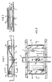
- Figure 1 is a longitudinal sectional view along 1-1 of Figure 2, showing the element hung on the support, but not yet clamped thereon;
- Figure 2 is a section along 11-11 of Figure 1;
- Figure 3 is a section along III-III of Figure 1.
- This element 1 which must be fixed on a support 2.
- This element 1 is constituted for example, by a strip which must be fixed on the body of a motor vehicle.
- the element 1 has a U-shaped section and its bearing edges are preferably furnished with flexible midsoles 3 coming into contact with the support 2. It has, at an intermediate location of its height, a series of pairs of internal transverse bars 1a and 1b, these pairs each corresponding to a fixing point on the support 2, the fixing point being constituted by an anchor pin 4 whose head 4a is slightly spaced from the wall of the support.
- Element 1 is equipped with a series of elastic blades 5 curved in the shape of a flared U, each of which is associated with a pair of bars 1a and 1b and whose width is slightly less than the internal width of element 1 ; the curved ends 5a and 5b of the blades are engaged under the bars 1a and 1b.
- Each of these blades has a transverse buttonhole 6 at mid-length. One end of this buttonhole is in the center of the blade; its opposite end is widened as indicated in 6a and has a diameter sufficient to allow the passage of the head 4a of an anchor pin 4.
- the blade 5 In the free state, the blade 5 extends over a height less than that of the element 1, and is therefore set back relative to the bearing plane of the soles 3. But, before mounting this element on the support 2, a pin 7, the shape of which is similar to that of a hairpin, was engaged laterally under the flexible soles 3 and on the lower central part 5c of the blade 5, on either side of its buttonhole 6. This operation resulted in an increase in the deflection of the blade, the middle part 5c then protrudes under the element 1 and which is now clamped on this element, its ends 5a and 5b being braced on the bars la and 1b.
Landscapes
- Engineering & Computer Science (AREA)
- General Engineering & Computer Science (AREA)
- Mechanical Engineering (AREA)
- Clamps And Clips (AREA)
- Insertion Pins And Rivets (AREA)
- Snaps, Bayonet Connections, Set Pins, And Snap Rings (AREA)
Claims (5)
Applications Claiming Priority (2)
| Application Number | Priority Date | Filing Date | Title |
|---|---|---|---|
| FR8408622A FR2564909B1 (fr) | 1984-05-25 | 1984-05-25 | Fixation invisible sur un rapport d'un element rapporte |
| FR8408622 | 1984-05-25 |
Publications (2)
| Publication Number | Publication Date |
|---|---|
| EP0170532A1 EP0170532A1 (de) | 1986-02-05 |
| EP0170532B1 true EP0170532B1 (de) | 1988-02-24 |
Family
ID=9304608
Family Applications (1)
| Application Number | Title | Priority Date | Filing Date |
|---|---|---|---|
| EP19850400812 Expired EP0170532B1 (de) | 1984-05-25 | 1985-04-25 | Unsichtbare Befestigung von einem hierzugefügten Teil auf einem Träger |
Country Status (3)
| Country | Link |
|---|---|
| EP (1) | EP0170532B1 (de) |
| DE (1) | DE3561672D1 (de) |
| FR (1) | FR2564909B1 (de) |
Families Citing this family (1)
| Publication number | Priority date | Publication date | Assignee | Title |
|---|---|---|---|---|
| FR2629878B1 (fr) * | 1988-04-12 | 1990-07-06 | Renault | Dispositif de fixation |
Family Cites Families (1)
| Publication number | Priority date | Publication date | Assignee | Title |
|---|---|---|---|---|
| GB1014137A (en) * | 1963-05-09 | 1965-12-22 | Chicago United Products Compan | Fastening assembly |
-
1984
- 1984-05-25 FR FR8408622A patent/FR2564909B1/fr not_active Expired
-
1985
- 1985-04-25 EP EP19850400812 patent/EP0170532B1/de not_active Expired
- 1985-04-25 DE DE8585400812T patent/DE3561672D1/de not_active Expired
Also Published As
| Publication number | Publication date |
|---|---|
| DE3561672D1 (en) | 1988-03-31 |
| FR2564909B1 (fr) | 1986-09-05 |
| FR2564909A1 (fr) | 1985-11-29 |
| EP0170532A1 (de) | 1986-02-05 |
Similar Documents
| Publication | Publication Date | Title |
|---|---|---|
| EP0296898B1 (de) | Schuhbefestigungsvorrichtung an einem Fahrradpedal | |
| EP2943693A1 (de) | Klemme zur befestigung einer platte an einem halter und auf diese weise hergestellte anordnung | |
| FR2784629A1 (fr) | Dispositif de fixation pour siege de vehicule, siege de vehicule comportant un tel dispositif, et glissiere pour un tel siege | |
| FR2868023A1 (fr) | Dossier de siege de vehicule adapte pour permettre la fixation d'un siege pour enfant et siege de vehicule comprenant un tel dossier | |
| FR2579693A1 (fr) | Goujon a souder et agrafe se montant sur ce goujon | |
| FR2857314A1 (fr) | Dispositif de fixation des parties laterales en forme de crosse du pare-chocs avant d'un vehicule automobile aux ailes de ce dernier | |
| FR3128257A1 (fr) | Ensemble de serrage de sangle de fixation | |
| EP0170532A1 (de) | Unsichtbare Befestigung von einem hierzugefügten Teil auf einem Träger | |
| FR2630311A1 (fr) | Dispositif de blocage rapide pour glissieres extensibles de tiroirs | |
| EP1209370A1 (de) | Vorrichtung zum Befestigen eines Bauteils an einen Träger und diese Vorrichtung verwendendes System zum kontrollierten, formschlüssigen Befestigen eines hölzernen Kraftfahrzeugbauteils | |
| EP0683327A1 (de) | Befestigungselement für Kabel, Rohre oder dergleichen | |
| FR2796344A1 (fr) | Mecanisme d'ancrage et d'articulation, notamment pour un siege arriere d'un vehicule automobile | |
| EP1498305B1 (de) | Befestigungsvorrichtung des Hintersitzkissens eines Kraftfahrzeuges. | |
| FR2547194A1 (fr) | Crochet d'amarrage de brancard pour ambulance | |
| FR2786449A1 (fr) | Connecteur d'essuie-glace de vehicule automobile | |
| EP0878353A1 (de) | Vorrichtung zur vorübergehenden Befestigung einer Beleuchtungs- oder Signaleinrichtung auf der Karosserie eines Kraftfahrzeuges | |
| FR2681025A1 (fr) | Balai d'essuie-glace comportant des moyens d'arret longitudinal de la lame d'essuyage. | |
| WO2018172642A1 (fr) | Piece d'habillage de carrosserie de vehicule | |
| FR2730871A1 (fr) | Dispositif de fixation d'un faisceau de cables sur une structure quelconque | |
| FR2475107A1 (fr) | Dispositif de fixation d'un chassis de porte, notamment pour une porte de garage | |
| FR2764785A1 (fr) | Dispositif de fixation d'un accotoir de sommier | |
| CH260678A (fr) | Fermoir pour bracelet. | |
| EP3390161B1 (de) | Vorrichtung zur befestigung eines abdeckelements an einer fensterpfostenstruktur | |
| FR2631085A1 (fr) | Dispositif d'accrochage notamment d'un appareil de chauffage electrique a une paroi | |
| FR2855467A1 (fr) | Dispositif de fixation d'un siege sur un plancher de vehicule et siege de vehicule comprenant un tel dispositif de fixation. |
Legal Events
| Date | Code | Title | Description |
|---|---|---|---|
| PUAI | Public reference made under article 153(3) epc to a published international application that has entered the european phase |
Free format text: ORIGINAL CODE: 0009012 |
|
| AK | Designated contracting states |
Designated state(s): DE GB IT |
|
| 17P | Request for examination filed |
Effective date: 19851206 |
|
| 17Q | First examination report despatched |
Effective date: 19870119 |
|
| GRAA | (expected) grant |
Free format text: ORIGINAL CODE: 0009210 |
|
| AK | Designated contracting states |
Kind code of ref document: B1 Designated state(s): DE GB IT |
|
| ITF | It: translation for a ep patent filed | ||
| GBT | Gb: translation of ep patent filed (gb section 77(6)(a)/1977) | ||
| REF | Corresponds to: |
Ref document number: 3561672 Country of ref document: DE Date of ref document: 19880331 |
|
| ITPR | It: changes in ownership of a european patent |
Owner name: OFFERTA DI LICENZA AL PUBBLICO |
|
| REG | Reference to a national code |
Ref country code: GB Ref legal event code: 746 |
|
| PLBE | No opposition filed within time limit |
Free format text: ORIGINAL CODE: 0009261 |
|
| STAA | Information on the status of an ep patent application or granted ep patent |
Free format text: STATUS: NO OPPOSITION FILED WITHIN TIME LIMIT |
|
| 26N | No opposition filed | ||
| PGFP | Annual fee paid to national office [announced via postgrant information from national office to epo] |
Ref country code: GB Payment date: 19930420 Year of fee payment: 9 |
|
| PGFP | Annual fee paid to national office [announced via postgrant information from national office to epo] |
Ref country code: DE Payment date: 19930423 Year of fee payment: 9 |
|
| ITTA | It: last paid annual fee | ||
| PG25 | Lapsed in a contracting state [announced via postgrant information from national office to epo] |
Ref country code: GB Effective date: 19940425 |
|
| GBPC | Gb: european patent ceased through non-payment of renewal fee |
Effective date: 19940425 |
|
| PG25 | Lapsed in a contracting state [announced via postgrant information from national office to epo] |
Ref country code: DE Effective date: 19950103 |