EP0170577A1 - Dispositif de commande de l'ouverture d'une serrure de portière de véhicule automobile - Google Patents
Dispositif de commande de l'ouverture d'une serrure de portière de véhicule automobile Download PDFInfo
- Publication number
- EP0170577A1 EP0170577A1 EP85401373A EP85401373A EP0170577A1 EP 0170577 A1 EP0170577 A1 EP 0170577A1 EP 85401373 A EP85401373 A EP 85401373A EP 85401373 A EP85401373 A EP 85401373A EP 0170577 A1 EP0170577 A1 EP 0170577A1
- Authority
- EP
- European Patent Office
- Prior art keywords
- cleat
- lock
- opening
- toothed wheel
- slide
- Prior art date
- Legal status (The legal status is an assumption and is not a legal conclusion. Google has not performed a legal analysis and makes no representation as to the accuracy of the status listed.)
- Granted
Links
- 230000008878 coupling Effects 0.000 claims abstract description 9
- 238000010168 coupling process Methods 0.000 claims abstract description 9
- 238000005859 coupling reaction Methods 0.000 claims abstract description 9
- 230000002093 peripheral effect Effects 0.000 claims 1
- 230000000903 blocking effect Effects 0.000 abstract 1
- 238000006073 displacement reaction Methods 0.000 description 3
- 240000000966 Allium tricoccum Species 0.000 description 1
- 230000004323 axial length Effects 0.000 description 1
- 210000003323 beak Anatomy 0.000 description 1
- 230000005540 biological transmission Effects 0.000 description 1
- 230000007423 decrease Effects 0.000 description 1
- 230000000994 depressogenic effect Effects 0.000 description 1
- 230000003100 immobilizing effect Effects 0.000 description 1
- 210000000056 organ Anatomy 0.000 description 1
Images

Classifications
-
- E—FIXED CONSTRUCTIONS
- E05—LOCKS; KEYS; WINDOW OR DOOR FITTINGS; SAFES
- E05B—LOCKS; ACCESSORIES THEREFOR; HANDCUFFS
- E05B81/00—Power-actuated vehicle locks
- E05B81/12—Power-actuated vehicle locks characterised by the function or purpose of the powered actuators
- E05B81/14—Power-actuated vehicle locks characterised by the function or purpose of the powered actuators operating on bolt detents, e.g. for unlatching the bolt
-
- E—FIXED CONSTRUCTIONS
- E05—LOCKS; KEYS; WINDOW OR DOOR FITTINGS; SAFES
- E05B—LOCKS; ACCESSORIES THEREFOR; HANDCUFFS
- E05B85/00—Details of vehicle locks not provided for in groups E05B77/00 - E05B83/00
- E05B85/20—Bolts or detents
- E05B85/24—Bolts rotating about an axis
- E05B85/243—Bolts rotating about an axis with a bifurcated bolt
Definitions
- the present invention relates to locks for doors of a motor vehicle and in particular locks comprising a locking mechanism intended to lock the bolt in its open and closed positions and an electromechanical device for controlling this mechanism for the opening of the lock qüi - are connected by a sliding coupling member moved by the electromechanical device and provided with means for driving an articulated lock of the locking mechanism.
- the electromechanical device generally comprises a toothed wheel driven by an electric motor and moving a driving cleat which cooperates with a projection of the sliding coupling member, as well as an electric device which stops the motor. and consequently interrupts the drive of the toothed wheel when the sliding member has reached the desired position of opening or closing. It is therefore necessary to provide inside the lock a certain number of electrical contactors as well as corresponding electrical connections, which makes the production of the lock complex, but above all requires providing effective protection against humidity and in particular rainwater.
- the present invention aims to remedy these drawbacks by providing an efficient and safe control device which does not use an internal electrical contactor in the lock.
- the subject of this invention is in fact a device for controlling the opening of a lock of the above type, in which a screw driven in rotation by an electric motor displaces a driving cleat with a projection of a coupling slide which comprises means creating a link :: drive sound between the cleat and the wheel during a determined angular travel of the latter which corresponds to the displacement of the slide between its closed and open positions of the lock, this connection being automatically disengaged by the arrival of the slide in the open position.
- the locking mechanism immobilizing the slide in each of its open and closed positions and the drive link between the cleat and the toothed wheel being automatically interrupted when the slide arrives in the open position, it does not It is not essential to stop the engine immediately.
- the toothed wheel can indeed continue to rotate for an indefinite time without changing the position of the lock.
- the means for creating a drive connection between the cleat and the toothed wheel comprise ramps which cooperate with balls to push back the cleat in engagement with the wheel.
- the balls and the ramps are mounted respectively on two rings coaxial with the toothed wheel, one of which is fixed, while the other is moved by the slide arriving at the end of the opening or closing.
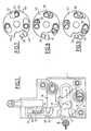
- the lock for the door of a motor vehicle shown in Fig. 1 and 2 comprises a box 1 provided with an opening 2 for introducing a keeper G and enclosing a pivoting bolt 4 which comprises a notch 6 for housing the keeper between two nozzles 8 and 10 respectively, this bolt pivoting about a hinge axis 12 and being returned to its open position shown in FIG. 1 by a spring 14 mounted on the axis 12.
- the housing 1 also contains a locking mechanism intended in particular to block the keeper in the opening.
- This mechanism comprises a latch 16 pivotally mounted on an axis 17 and forming a hook 18 for cooperation with the beaks of the bolt 4.
- the latch 16 At its end opposite to the axis 17, the latch 16 comprises a latching finger 20 which comes fit into a cavity 22 formed at the lower end of a slide 24 provided with a projection or lug 26 and thus constituting a coupling and transmission member movement between the locking mechanism and a device for controlling the opening of this mechanism.
- the slide is pushed back towards the opening 2, that is to say towards its locking position by a spring 28 mounted between it and a fixed cleat 30 of the housing.
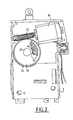
- the movement of the slide 24 against the action of the spring 28, that is to say towards the open position of the door, is controlled from an electric motor 30 (FIG. 2) which is supplied from outside the housing. and causes the rotation of a screw 32.
- This screw 32 is engaged with a toothed wheel 34 which is free to rotate on an axis 35 fixed in the housing 1.
- the wheel 34 is hollow and its bottom 36 which is crossed by the axis 35, has on its internal surface radial grooves 38 (Fig.3).
- Radial grooves 40 similar to the grooves 38 are formed on a disc 41 which is also mounted on the axis 35 but is both free to rotate and capable of moving axially relative to this axis.
- the disc 41 is mounted inside the toothed wheel 34 and carries on its face opposite to the toothing 40 a tab 42 projecting outside this wheel.
- the cleat 42 has an axial length such that it successively passes through a notch 43 formed at the periphery of a fixed washer 44 secured to the axis 35 then a notch 45 formed at the periphery of a movable washer 46 mounted to rotate freely on axis 35.
- the fixed washer 44 is pierced with a number of holes 48 which pass through it and each serve as a housing for a ball 50 which is thus capable of projecting from one or the other of the faces of the washer 44.
- the ron fixed delle 46 Opposite from each of the holes 48, the ron fixed delle 46 has a curved recess 52 coaxially with the washer 46, one of the side walls of which forms an inclined ramp 54 so that the depth of the recess decreases progressively in this direction (FIG. 4).
- the balls are aligned with the deep part of the corresponding recess 52 (Fig.5) or with the upper part of the ramp 54 as shown in Fig. 6.
- the balls 50 are thus inside the recesses 52, they only make a very slight projection on the opposite face of the fixed washer 44 so that the disc 41 is free between this washer and the bottom 36 of the wheel toothed 34.
- the washer 46 having rotated, the balls have been pushed back by the ramps 54 until they protrude significantly on the opposite face of the fixed washer 44, the disc 41 is pressed by these balls against the bottom 36 of the toothed wheel 34. Consequently, the grooves 40 of the disc 41 come into engagement with the grooves 38 of the bottom 36 of the toothed wheel and secure these two rotating members.
- the cleat 42 is consequently driven by the toothed wheel 34.
- the notches 45 of the movable washer 46 and 43 of the fixed washer 44 are also crossed by the projection or the lug 26 of the slide 24 so that the movement of the cleat 42 in a clockwise direction considering the Figs .7,8 and 9 causes that of the slide 24.
- the slide 24 In the closed position of the lock, that is to say when the keeper G is blocked inside the notch 6 of the bolt 4 and the spout 8 of this bolt is immobilized by the hook 18 of the latch 16, the slide 24 is in the depressed position, that is to say in its position closest to the opening of the housing 1.
- the lug 26 is in contact with the cleat 42 which is itself supported on the edge of the notch 45 of the washer 46 as shown in Fig. 7. At this moment, the washer 46 is in the same position as in FIG. 6.
- the ramps 54 therefore push the balls 50_ outwards, that is to say in the direction of the disc 41.
- the grooves 40 and 38 are engaged and the cleat 42 is integral with the toothed wheel.
- the rotation of the screw 32 causes that of the toothed wheel 34 and causes the displacement of the cleat 42 in the notch 45.
- the cleat 42 entrains the lug 26 until it contacts with the opposite end of the notch 45 then the toothed wheel 34 continuing to rotate, pushes the washer 46 which in turn turns.
- each of the recesses 52 moves under the ball 50 and allows it to descend along the ramp 54 to penetrate into the portion of greatest depth of the recess, and thus free the disc 41 which is no longer clamped against the toothed wheel 34.
- the slope of the grooves 38 and 40 is such that the disc 41 deviates from itself from the bottom 36 of the toothed wheel 34.
- This toothed wheel 34 can continue to rotate under the action of the screw 32 and the motor 30, but the disc 41 and the cleat 42 are no longer driven.
- the slide 24 has been moved away from the opening 2 by driving the finger 20 so that the latch 16 has pivoted and released the bolt 4.
- the lock is unlocked and the keeper G is free.
- the slide 24 and consequently the lug 26 are pushed back by the spring 28 in direct tion of the opening 2 and tend to pivot the latch 16 in the direction of the bolt 4.
- the lug 26 therefore exerts a force on the cleat 42 which, like the disc 41 is free to rotate, the grooves 38 and 40 being disengaged .
- the lug 26 therefore pushes the cleat 42 back into the notch 45 until the hook 18 of the latch 16 abuts the spout 10 of the bolt 4 and stops the movement (FIGS. 1 and 9).
- the mechanism is then immobilized in the open position of the lock, the bolt 4 being ready to receive the keeper G.
- the keeper G enters the opening 2 then in the notch 6 of the bolt 4 and pushes the latter until it is released from the hook 18 of the latch 16.
- the slide 24 moves by driving the lug 26.
- the latter pushes the cleat 42 to the end of the notch 45 and even causes the rotation of the washer 46 to bring it in the clutch position shown in Fig.6 and 7.
- the locking mechanism blocks the keeper G in the bolt 4 while the cleat 42 of the control device is made integral with the toothed wheel 34 and is ready to be driven by the motor 3 0 as soon as it will be supplied, for example via external contactors known type that does not need to be described or shown.
- the device for controlling the opening which has just been described enables the desired displacement of the coupling slide of the locking mechanism to be obtained safely and effectively without requiring the use of contactors or other electrical components. inside the lock.
- This movement is in fact independent of the duration of supply of the motor 30 which can without danger actuate and even drive the toothed wheel 34 for a period significantly greater than that necessary for opening, since the cleat 42 is automatically made independent of this wheel, when the slider reaches the useful end of travel.
- the return to the cleat drive position is also automatic when the door is closed.
Landscapes
- Lock And Its Accessories (AREA)
- Power-Operated Mechanisms For Wings (AREA)
Abstract
Description
- La présente invention concerne les serrures pour portières de véhicule automobile et notamment les serrures comportant un mécanisme de verrouillage destiné à bloquer le pêne dans ses positions d'ouverture et de fermeture et un dispositif électromécanique de commande de ce mécanisme en vue de l'ouverture de la serrure qüi - sont reliés par un organe de couplage coulissant déplacé par le dispositif électromécanique et muni de moyens d'entrainement d'un verrou articulé du mécanisme de verrouillage.
- Dans les serrures de ce type, le dispositif électromécanique comporte généralement une roue dentée entrainée par un moteur électrique et déplaçant un taquet d'entrainement qui coopére avec une saillie de l'organe de couplage coulissant, ainsi qu'un dispositif électrique qui arrête le moteur et par suite interrompt l'entrainement de la roue dentée lorsque l'organe coulissant a atteint la position désirée d'ouverture ou de fermeture. Il est donc nécessaire de prévoir à l'intérieur de la serrure un certain nombre de contacteurs électriques ainsi que des raccordements électriques correspondants, ce qui rend complexe la réalisation de la serrure, mais surtout oblige à prévoir une protection efficace contre l'humidité et notamment l'eau de pluie.
- La présente invention a pour but de remédier à ces inconvénients en fournissant un dispositif de commande efficace et sûr qui n'utilise pas de contacteur électrique interne à la serrure.
- Cette invention a en effet pour objet un dispositif de commande de l'ouverture d'une serrure du type ci-dessus, dans lequel une vis entrainée en rotation par un moteur électrique déplace un taquet d'en- trainement d'une saillie d'un coulisseau de couplage qui comporte des moyens créant une lia::son d'entrai- nement entre le taquet et la roue pendant une course angulaire déterminée de cette dernière qui correspond au déplacement du coulisseau entre ses positions de fermeture et d'ouverture de la serrure, cette liaison étant automatiquement débrayée par l'arrivée du coulisseau en position d'ouverture.
- Le mécanisme de verrouillage immobilisant le coulisseau dans chacune de ses positions d'ouverture et de fermeture et la liaison d'entrainement entre le taquet et la roue dentée étant automatiquement interrompue lors de l'arrivée du coulisseau en position d'ouverture, il n'est pas indispensable d'arrêter immédiatement le moteur. La roue dentée peut en effet continuer à tourner pendant un temps indéterminé sans modifier la position de la serrure.
- Selon une autre caractéristique de l'invention, les moyens pour créer une liaison d'entrainement entre le taquet et la roue dentée comportent des rampes qui coopèrent avec des billes pour repousser le taquet en prise avec la roue.
- Selon un mode de réalisation préféré, les billes et les rampes sont montées respectivement sur deux couronnes coaxiales à la roue dentée dont l'une est fixe, tandis que l'autre est déplacée par le coulisseau arrivant en fin de course d'ouverture ou de fermeture.
- La description ci-dessous d'un mode de réalisation donné à titre d'exemple non limitatif et représenté aux dessins annexés fera d'ailleurs ressortir les avantages et caractéristiques de l'invention.
- Sur ces dessins :
- - la Fig.1 est une vue schématique, en plan, du mécanisme de verrouillage de la serrure;
- - la Fig.2 est une vue analogue à la Fig.1 montrant le dispositif de commande de l'ouverture;
- - la Fig.3 est une vue en perspective éclatée du mécanisme d'entrainement du coulisseau;
- - la Fig.4 est une vue suivant la flèche F de la Fig.3 montrant les rampes d'entrainement;
- - les Fig.5 et 6 sont des vues partielles, en coupe du mécanisme d'entrainement assemblé, respectivement en position débrayée et en position d'en- trainement;
- - les Fig.7,8 et 9 sont des vues schématiques montrant les positions des organes d'entrainement respectivement lorsque la serrure est fermée, ouverte et en position intermédiaire.
- La serrure pour portière de véhicule automobile représentée sur les Fig.1 et 2 comporte un boitier 1 muni d'une ouverture 2 d'introduction d'une gâche G et enfermant un pêne pivotant 4 qui comporte une encoche 6 de logement de la gâche entre deux becs respectivement 8 et 10, ce pêne pivotant autour d'un axe d'articulation 12 et étant rappelé dans sa position d'ouverture représentée sur la Fig.1 par un ressort 14 monté sur l'axe 12.
- Le boîtier 1 contient également un mécanisme de verrouillage destiné notamment à bloquer la gâche dans l'ouverture. Ce mécanisme comporte un verrou 16 monté pivotant sur un axe 17 et formant un crochet 18 de coopération avec les becs du pêne 4. A son extrémité opposée à l'axe 17, le verrou 16 comporte un doigt d'accrochage 20 qui vient s'emboiter dans une cavité 22 formée à l'extrémité inférieure d'un coulisseau 24 muni d'une saillie ou ergot 26 et constituant ainsi un organe de couplage et de transmission de mouvement entre le mécanisme de verrouillage et un dispositif de commande de l'ouverture de ce mécanisme.
- Le coulisseau est repoussé en direction de l'ouverture 2, c'est à dire vers sa- position de verrouillage par un ressort 28 monté entre lui et un taquet fixe 30 du boitier.
- Le déplacement du coulisseau 24 contre l'action du ressort 28 c'est à dire vers la position d'ouverture de la porte est commandé à partir d'un moteur électrique 30 (Fig.2) qui est alimenté depuis l'extérieur du boîtier et provoque la rotation d'une vis 32. Cette vis 32 est en prise avec une roue dentée 34 qui est libre en rotation sur un axe 35 fixé dans le boitier 1. En fait, la roue 34 est creuse et son fond 36 qui est traversé par l'axe 35, comporte sur sa surface interne des cannelures radiales 38 (Fig.3). Des cannelures radiales 40 analogues aux cannelures 38 sont formées sur un disque 41 qui est également monté sur l'axe 35 mais est à la fois libre en rotation et susceptible de se déplacer axialement par rapport à cet axe. Le disque 41 est monté à l'intérieur de la roue dentée 34 et porte sur sa face opposée à la denture 40 un taquet 42 en saillie à l'extérieur de cette roue. Le taquet 42 a une longueur axiale telle qu'il traverse successivement une encoche 43 ménagée à la périphérie d'une rondelle fixe 44 solidaire de l'axe 35 puis une encoche 45 ménagée à la périphérie d'une rondelle mobile 46 montée libre en rotation sur l'axe 35.
- La rondelle fixe 44 est percée d'un certain nombre de trous 48 qui la traversent et servent chacun de logement à une bille 50 qui est ainsi susceptible de faire saillie sur l'une ou l'autre des faces de la rondelle 44. En regard de chacun des trous 48,la rondelle fixe 46 comporte un évidement 52 incurvé coaxia- lement à la rondelle 46 dont l'une des parois latérales forme une rampe inclinée 54 de sorte que la profondeur de l'évidement décroit progressivement dans- cette direction (Fig.4).
- Selon la position de la rondelle 46 par rapport à la rondelle fixe 44, les billes se trouvent alignées avec la partie profonde de l'évidement 52 correspondant (Fig.5) ou avec la partie supérieure de la rampe 54 comme le montre la Fig.6. Lorsque les billes 50 sont ainsi à l'intérieur des évidements 52, elles ne font qu'une saillie très faible sur la face opposée de la rondelle fixe 44 de sorte que le disque 41 est libre entre cette rondelle et le fond 36 de la roue dentée 34. Au contraire, lorsque la rondelle 46 ayant tourné, les billes ont été repoussées par les rampes 54 jusqu'à faire saillie de manière importante sur la face opposée de la rondelle fixe 44,le disque 41 est serré par ces billes contre le fond 36 de la roue dentée 34. En conséquence, les cannelures 40 du disque 41 viennent en prise avec les cannelures 38 du fond 36 de la roue dentée et solidarisent ces deux organes en rotation. Le taquet 42 est par suite entrainé par la roue dentée 34.
- Les encoches 45 de la rondelle mobile 46 et 43 de la rondelle fixe 44 sont également traversées par la saillie ou l'ergot 26 du coulisseau 24 de sorte que le déplacement du taquet 42 dans le sens des aiguilles d'une montre en considérant les Fig.7,8 et 9 provoque celui du coulisseau 24.
- Dans la position de fermeture de la serrure, c'est à dire lorsque la gâche G est bloquée à l'intérieur de l'encoche 6 du pêne 4 et que le bec 8 de ce pêne est immobilisé par le crochet 18 du verrou 16, le coulisseau 24 est en position enfoncée, c'est à dire dans sa position la plus proche de l'ouverture du boîtier 1. L'ergot 26 est en contact avec le taquet 42 qui est lui-même appuyé sur le bord de l'encoche 45 de la rondelle 46 comme le montre la Fig.7. A ce moment, la rondelle 46 est dans la même position que sur la Fig.6. Les rampes 54 repoussent donc les billes 50_ vers l'extérieur, c'est à dire en direction du disque 41. Les cannelures 40 et 38 sont en prise et le taquet 42 est solidaire de la roue dentée.
- Si à ce moment, le moteur 30 est excité, la rotation de la vis 32 entraine celle de la roue dentée 34 et provoque le déplacement du taquet 42 dans l'encoche 45. Le taquet 42 entraine l'ergot 26 jusqu'à son contact avec l'extrémité opposée de l'encoche 45 puis la roue dentée 34 continuant à tourner, pousse la rondelle 46 qui tourne à son tour. Au cours de cette rotation, chacun des évidements 52 se déplace sous la bille 50 et permet à celle-ci de descendre le long de la rampe 54 pour pénétrer dans la partie de plus grande profondeur de l'évidement, et ainsi de libérer le disque 41 qui n'est plus serré contre la roue dentée 34. La pente des cannelures 38 et 40 est telle que le disque 41 s'écarte de lui-même du fond 36 de la roue dentée 34.
- Cette roue dentée 34 peut continuer à tourner sous l'action de la vis 32 et du moteur 30, mais le disque 41 et le taquet 42 ne sont plus entrainés. Le coulisseau 24 a été écarté de l'ouverture 2 en entrainant le doigt 20 de sorte que le verrou 16 a pivoté et libéré le pêne 4. La serrure est déverrouillée et la gâche G est libre.
- Par contre, le coulisseau 24 et par suite l'ergot 26 sont repoussés par le ressort 28 en direction de l'ouverture 2 et tendent à faire pivoter le verrou 16 en direction du pêne 4. L'ergot 26 exerce donc un effort sur le taquet 42 qui, comme le disque 41 est libre en rotation, les cannelures 38 et 40 étant débrayées. L'ergot 26 repousse donc le taquet 42 dans l'encoche 45 jusqu'au moment où le crochet 18 du verrou 16 vient buter sur le bec 10 du pêne 4 et ar- rète le déplacement (Fig. 1 et 9). Le mécanisme est alors immobilisé en position d'ouverture de la serrure, le pêne 4 étant prêt à recevoir la gâche G.
- Lors de la fermeture de la portière, la gâche G pénètre dans l'ouverture 2 puis dans l'encoche 6 du pêne 4 et repousse ce dernier jusqu'à ce qu'il soit dégagé du crochet 18 du verrou 16. A ce moment, sous l'action du ressort 28,le coulisseau 24 se déplace en entrainant l'ergot 26. Ce dernier repousse le taquet 42 jusqu'à l'extrémité de l'encoche 45 et provoque même la rotation de la rondelle 46 pour l'amener dans la position d'embrayage représentée sur les Fig.6 et 7. A ce moment, le mécanisme de verrouillage bloque la gâche G dans le pêne 4 tandis que le taquet 42 du dispositif de commande est rendu solidaire de la roue dentée 34 et est prêt à être entrainé par le moteur 30 dès que celui-ci sera alimenté, par exemple par l'intermédiaire de contacteurs extérieurs de type connu qui n'ont pas besoin d'être décrits ni représentés.
- On constate que le dispositif de commande de l'ouverture qui vient d'être décrit permet d'obtenir de façon sûre et efficace le déplacement désiré du coulisseau de couplage du mécanisme de verrouillage sans nécessiter l'utilisation de contacteurs ou autres organes électriques à l'intérieur de la serrure. Ce déplacement est en effet indépendant de la durée d'alimentation du moteur 30 qui peut sans danger fonctionner et même entrainer la roue dentée 34 pendant une période nettement supérieure à celle nécessaire pour l'ouverture, puisque le taquet 42 est automatiquement rendu indépendant de cette roue, lorsque le coulisseau arrive en fin de course utile. Le retour à la position d'entrainement du taquet s'effectue également de manière automatique lors de la fermeture de la porte.
Claims (8)
Applications Claiming Priority (2)
| Application Number | Priority Date | Filing Date | Title |
|---|---|---|---|
| FR8411599 | 1984-07-20 | ||
| FR8411599A FR2567949B1 (fr) | 1984-07-20 | 1984-07-20 | Dispositif de commande de l'ouverture d'une serrure de portiere de vehicule automobile |
Publications (2)
| Publication Number | Publication Date |
|---|---|
| EP0170577A1 true EP0170577A1 (fr) | 1986-02-05 |
| EP0170577B1 EP0170577B1 (fr) | 1988-06-15 |
Family
ID=9306356
Family Applications (1)
| Application Number | Title | Priority Date | Filing Date |
|---|---|---|---|
| EP19850401373 Expired EP0170577B1 (fr) | 1984-07-20 | 1985-07-05 | Dispositif de commande de l'ouverture d'une serrure de portière de véhicule automobile |
Country Status (4)
| Country | Link |
|---|---|
| EP (1) | EP0170577B1 (fr) |
| DE (1) | DE3563367D1 (fr) |
| ES (1) | ES288363Y (fr) |
| FR (1) | FR2567949B1 (fr) |
Cited By (7)
| Publication number | Priority date | Publication date | Assignee | Title |
|---|---|---|---|---|
| GB2241737A (en) * | 1987-09-21 | 1991-09-11 | Kelsey Hayes Co | Door lock actuator with centrifugal clutch |
| EP0808979A3 (fr) * | 1996-05-21 | 1998-03-18 | General Motors Corporation | Fermeture pour véhicule automobile |
| FR2757204A1 (fr) * | 1996-12-13 | 1998-06-19 | Deny | Serrure electrique |
| WO1999000572A1 (fr) * | 1997-06-26 | 1999-01-07 | Hyun Gyu Cho | Serrure electrique de portiere et systeme de verrouillage d'automobile |
| FR2821108A1 (fr) * | 2001-02-22 | 2002-08-23 | Valeo Securite Habitacle | Serrure d'ouvrant de vehicule automobile a maneton debrayable |
| WO2018185209A1 (fr) * | 2017-04-06 | 2018-10-11 | Cebi Italy S.P.A. | Verrou pour porte ou couvercle de véhicule à moteur |
| EP3511496A1 (fr) * | 2018-01-10 | 2019-07-17 | U-Shin France | Serrure a trois positions pour vehicule automobile |
Families Citing this family (1)
| Publication number | Priority date | Publication date | Assignee | Title |
|---|---|---|---|---|
| DE3935854A1 (de) * | 1989-10-27 | 1991-05-02 | Ikon Praezisionstechnik | Elektromotorischer antrieb fuer einen schliesszylinder |
Citations (3)
| Publication number | Priority date | Publication date | Assignee | Title |
|---|---|---|---|---|
| FR2474573A1 (fr) * | 1980-01-30 | 1981-07-31 | Dubois & Cie | Dispositif d'actionnement electrique pour un organe de manoeuvre de serrures et objets analogues |
| EP0099820A1 (fr) * | 1982-07-19 | 1984-02-01 | A. & M. COUSIN Etablissements COUSIN FRERES | Serrure électrique de sécurité plus spécialement pour portières de véhicules automobiles |
| EP0106725A1 (fr) * | 1982-10-12 | 1984-04-25 | Vachette | Serrure à commande électrique et circuit de commande de serrure de porte pour automobile |
-
1984
- 1984-07-20 FR FR8411599A patent/FR2567949B1/fr not_active Expired
-
1985
- 1985-07-05 EP EP19850401373 patent/EP0170577B1/fr not_active Expired
- 1985-07-05 DE DE8585401373T patent/DE3563367D1/de not_active Expired
- 1985-07-16 ES ES1985288363U patent/ES288363Y/es not_active Expired
Patent Citations (3)
| Publication number | Priority date | Publication date | Assignee | Title |
|---|---|---|---|---|
| FR2474573A1 (fr) * | 1980-01-30 | 1981-07-31 | Dubois & Cie | Dispositif d'actionnement electrique pour un organe de manoeuvre de serrures et objets analogues |
| EP0099820A1 (fr) * | 1982-07-19 | 1984-02-01 | A. & M. COUSIN Etablissements COUSIN FRERES | Serrure électrique de sécurité plus spécialement pour portières de véhicules automobiles |
| EP0106725A1 (fr) * | 1982-10-12 | 1984-04-25 | Vachette | Serrure à commande électrique et circuit de commande de serrure de porte pour automobile |
Cited By (15)
| Publication number | Priority date | Publication date | Assignee | Title |
|---|---|---|---|---|
| GB2241737A (en) * | 1987-09-21 | 1991-09-11 | Kelsey Hayes Co | Door lock actuator with centrifugal clutch |
| GB2241737B (en) * | 1987-09-21 | 1992-04-15 | Kelsey Hayes Co | Improvements in and relating to clutches and actuators |
| EP0808979A3 (fr) * | 1996-05-21 | 1998-03-18 | General Motors Corporation | Fermeture pour véhicule automobile |
| FR2757204A1 (fr) * | 1996-12-13 | 1998-06-19 | Deny | Serrure electrique |
| WO1999000572A1 (fr) * | 1997-06-26 | 1999-01-07 | Hyun Gyu Cho | Serrure electrique de portiere et systeme de verrouillage d'automobile |
| FR2821108A1 (fr) * | 2001-02-22 | 2002-08-23 | Valeo Securite Habitacle | Serrure d'ouvrant de vehicule automobile a maneton debrayable |
| EP1234936A1 (fr) * | 2001-02-22 | 2002-08-28 | Valeo Sécurité Habitacle | Serrure d'ouvrant de véhicule automobile à maneton débrayable |
| US6712407B2 (en) | 2001-02-22 | 2004-03-30 | Valeo Securite Habitacle | Lock for a motor vehicle opening leaf with a disengageable wrist pin |
| WO2018185209A1 (fr) * | 2017-04-06 | 2018-10-11 | Cebi Italy S.P.A. | Verrou pour porte ou couvercle de véhicule à moteur |
| EP3511496A1 (fr) * | 2018-01-10 | 2019-07-17 | U-Shin France | Serrure a trois positions pour vehicule automobile |
| WO2019138013A1 (fr) * | 2018-01-10 | 2019-07-18 | U-Shin France | Serrure a trois positions pour vehicule automobile |
| CN111699295A (zh) * | 2018-01-10 | 2020-09-22 | 有信法国 | 用于机动车辆的三位置式闩锁 |
| US20200340277A1 (en) * | 2018-01-10 | 2020-10-29 | U-Shin France | Motor vehicle lock with three positions |
| CN111699295B (zh) * | 2018-01-10 | 2022-06-14 | 有信法国 | 用于机动车辆的三位置式闩锁 |
| US11572717B2 (en) | 2018-01-10 | 2023-02-07 | U-Shin France | Motor vehicle lock with three positions |
Also Published As
| Publication number | Publication date |
|---|---|
| ES288363U (es) | 1986-04-16 |
| FR2567949B1 (fr) | 1986-12-26 |
| DE3563367D1 (en) | 1988-07-21 |
| FR2567949A1 (fr) | 1986-01-24 |
| EP0170577B1 (fr) | 1988-06-15 |
| ES288363Y (es) | 1986-12-01 |
Similar Documents
| Publication | Publication Date | Title |
|---|---|---|
| EP0805078B1 (fr) | Dispositif de verrouillage motorisé pour véhicule automobile comportant des moyens perfectionnés de limitation de la course du pêne | |
| EP0593371B1 (fr) | Mécanisme d'actionnement d'un interrupteur à trois positions | |
| EP0959206B1 (fr) | Serrure de porte de véhicule automobile à condamnation électrique | |
| EP0313454B1 (fr) | Serrure assistée à pêne rotatif | |
| EP0082761A1 (fr) | Serrure, notamment pour véhicule automobile | |
| FR2768764A1 (fr) | Serrure electrique pour portiere de vehicule | |
| FR2503233A1 (fr) | Dispositif de reglage de position, notamment installation combinee de manoeuvre de vitre et de verrouillage central de porte de vehicule automobile | |
| EP0430732B1 (fr) | Mécanisme de commande d'ouverture d'une portière de véhicule automobile et portière le comportant | |
| FR2789717A1 (fr) | Serrure en trois parties, pour ouvrant de vehicule automobile | |
| FR2534739A1 (fr) | Contacteur de securite | |
| EP0159238B1 (fr) | Dispositif électromécanique de commande de l'ouverture d'une serrure et serrure de portière de véhicule automobile comportant un tel dispositif | |
| EP0060175A1 (fr) | Dispositif de verrouillage électrique, notamment d'un capot de véhicule automobile | |
| EP0170577B1 (fr) | Dispositif de commande de l'ouverture d'une serrure de portière de véhicule automobile | |
| FR2775717A1 (fr) | Dispositif d'ouverture/fermeture d'un ouvrant, notamment pour vehicule automobile | |
| EP0645511B1 (fr) | Serrure pour porte de véhicule automobile | |
| EP1201851B1 (fr) | Dispositif de poignée pour porte coulissante de véhicule automobile | |
| EP0426535A1 (fr) | Dispositif de verrouillage et d'entraînement d'une pièce mobile entre une première et une deuxième position et serrure de portière le comportant | |
| EP1234937B1 (fr) | Serrure électrique à actionnement de secours | |
| EP1048805B1 (fr) | Serrure manoeuvrable électriquement ou mécaniquement | |
| EP0230808B1 (fr) | Actionneur de condamnation d'une serrure de porte de véhicule automobile | |
| EP2207944B1 (fr) | Serrure pour ouvrant de vehicule automobile | |
| EP0102263B1 (fr) | Serrure à commande électrique pour portière de véhicule automobile | |
| WO1988007615A1 (fr) | Serrure a mecanisme de verrouillage-deverrouillage a l'aide d'un electro-aimant | |
| FR2815069A1 (fr) | Dispositif de deverrouillage de volets a battants entraines mecaniquement | |
| FR2474573A1 (fr) | Dispositif d'actionnement electrique pour un organe de manoeuvre de serrures et objets analogues |
Legal Events
| Date | Code | Title | Description |
|---|---|---|---|
| PUAI | Public reference made under article 153(3) epc to a published international application that has entered the european phase |
Free format text: ORIGINAL CODE: 0009012 |
|
| AK | Designated contracting states |
Designated state(s): DE GB IT |
|
| 17P | Request for examination filed |
Effective date: 19860104 |
|
| 17Q | First examination report despatched |
Effective date: 19870205 |
|
| GRAA | (expected) grant |
Free format text: ORIGINAL CODE: 0009210 |
|
| AK | Designated contracting states |
Kind code of ref document: B1 Designated state(s): DE GB IT |
|
| GBT | Gb: translation of ep patent filed (gb section 77(6)(a)/1977) | ||
| REF | Corresponds to: |
Ref document number: 3563367 Country of ref document: DE Date of ref document: 19880721 |
|
| RAP2 | Party data changed (patent owner data changed or rights of a patent transferred) |
Owner name: ECIA - EQUIPEMENTS ET COMPOSANTS POUR L'INDUSTRIE |
|
| ITF | It: translation for a ep patent filed | ||
| PLBE | No opposition filed within time limit |
Free format text: ORIGINAL CODE: 0009261 |
|
| STAA | Information on the status of an ep patent application or granted ep patent |
Free format text: STATUS: NO OPPOSITION FILED WITHIN TIME LIMIT |
|
| 26N | No opposition filed | ||
| ITPR | It: changes in ownership of a european patent |
Owner name: CAMBIO RAGIONE SOCIALE;ECIA - EQUIPEMENTS ET COMPO |
|
| PGFP | Annual fee paid to national office [announced via postgrant information from national office to epo] |
Ref country code: DE Payment date: 19930625 Year of fee payment: 9 |
|
| PGFP | Annual fee paid to national office [announced via postgrant information from national office to epo] |
Ref country code: GB Payment date: 19930629 Year of fee payment: 9 |
|
| ITTA | It: last paid annual fee | ||
| PG25 | Lapsed in a contracting state [announced via postgrant information from national office to epo] |
Ref country code: GB Effective date: 19940705 |
|
| GBPC | Gb: european patent ceased through non-payment of renewal fee |
Effective date: 19940705 |
|
| PG25 | Lapsed in a contracting state [announced via postgrant information from national office to epo] |
Ref country code: DE Effective date: 19950401 |