EP0170610A2 - Miroir parabolique démontable pour concentrer des rayons - Google Patents
Miroir parabolique démontable pour concentrer des rayons Download PDFInfo
- Publication number
- EP0170610A2 EP0170610A2 EP85730058A EP85730058A EP0170610A2 EP 0170610 A2 EP0170610 A2 EP 0170610A2 EP 85730058 A EP85730058 A EP 85730058A EP 85730058 A EP85730058 A EP 85730058A EP 0170610 A2 EP0170610 A2 EP 0170610A2
- Authority
- EP
- European Patent Office
- Prior art keywords
- parabolic mirror
- longitudinal
- struts
- mirror
- parabolic
- Prior art date
- Legal status (The legal status is an assumption and is not a legal conclusion. Google has not performed a legal analysis and makes no representation as to the accuracy of the status listed.)
- Withdrawn
Links
Images


Classifications
-
- G—PHYSICS
- G02—OPTICS
- G02B—OPTICAL ELEMENTS, SYSTEMS OR APPARATUS
- G02B7/00—Mountings, adjusting means, or light-tight connections, for optical elements
- G02B7/18—Mountings, adjusting means, or light-tight connections, for optical elements for prisms; for mirrors
- G02B7/182—Mountings, adjusting means, or light-tight connections, for optical elements for prisms; for mirrors for mirrors
- G02B7/183—Mountings, adjusting means, or light-tight connections, for optical elements for prisms; for mirrors for mirrors specially adapted for very large mirrors, e.g. for astronomy, or solar concentrators
-
- F—MECHANICAL ENGINEERING; LIGHTING; HEATING; WEAPONS; BLASTING
- F24—HEATING; RANGES; VENTILATING
- F24S—SOLAR HEAT COLLECTORS; SOLAR HEAT SYSTEMS
- F24S23/00—Arrangements for concentrating solar-rays for solar heat collectors
- F24S23/70—Arrangements for concentrating solar-rays for solar heat collectors with reflectors
- F24S23/71—Arrangements for concentrating solar-rays for solar heat collectors with reflectors with parabolic reflective surfaces
-
- H—ELECTRICITY
- H01—ELECTRIC ELEMENTS
- H01Q—ANTENNAS, i.e. RADIO AERIALS
- H01Q15/00—Devices for reflection, refraction, diffraction or polarisation of waves radiated from an antenna, e.g. quasi-optical devices
- H01Q15/14—Reflecting surfaces; Equivalent structures
- H01Q15/16—Reflecting surfaces; Equivalent structures curved in two dimensions [2D], e.g. paraboloidal
- H01Q15/161—Collapsible reflectors
-
- Y—GENERAL TAGGING OF NEW TECHNOLOGICAL DEVELOPMENTS; GENERAL TAGGING OF CROSS-SECTIONAL TECHNOLOGIES SPANNING OVER SEVERAL SECTIONS OF THE IPC; TECHNICAL SUBJECTS COVERED BY FORMER USPC CROSS-REFERENCE ART COLLECTIONS [XRACs] AND DIGESTS
- Y02—TECHNOLOGIES OR APPLICATIONS FOR MITIGATION OR ADAPTATION AGAINST CLIMATE CHANGE
- Y02E—REDUCTION OF GREENHOUSE GAS [GHG] EMISSIONS, RELATED TO ENERGY GENERATION, TRANSMISSION OR DISTRIBUTION
- Y02E10/00—Energy generation through renewable energy sources
- Y02E10/40—Solar thermal energy, e.g. solar towers
Definitions
- the invention relates to a collapsible parabolic mirror for concentrating radiation.
- parabolic mirrors for solar energy systems are either made of solid steel with glass mirrors or of lightweight construction with foil mirrors.
- Solid metal mirrors can be dismantled in principle, but their production is material and cost-intensive because molds have to be built either for casting segments or for deforming steel sheets. The mirroring itself is difficult because of the curved surfaces, so help is taken with mirror glass mosaics or mirror facets that can be stuck on.
- massive mirrors are heavy and require extensive investments in manufacturing, not to mention the expense of mirror tracking due to the masses to be tilted. If reflectors of different diameters are to be built, new shapes are always required.
- the present design as the subject of the application takes a fundamentally different route. It avoids expensive and heavy structures made from deep-drawn sheet metal or special blanks that are welded to create parabolic shapes, and uses (with one exception) only rectangular or almost rectangular parts made of plywood and stainless steel or aluminum.
- the reflector is assembled from these easily produced starting parts without conical blanks, the essence of the invention being that the reflector is assembled from now conical segments. According to the innovation there are now no restrictions regarding the diameter; it is not a problem to change the radius and also the curvature. Shapes are eliminated, the device for assembling the strips into segments are themselves basic building blocks of the segments.
- the resulting parabolic reflectors regardless of whether they are rotationally symmetrical bodies or sections of them, Thanks to their design as double shells and their internal spars, they have a high degree of self-stability and only require a concentric ring to be supported and to transmit the wind and gravitational forces acting on the reflector to the ground.
- Fig. 1 the parabolic mirror according to the invention is shown as a front view.
- the support frame is not shown since it is not the subject of the innovation.
- the parabolic mirror consists of segments 1, the number of which can be chosen between that required for a closed paraboloid and any smaller one.
- the segments can be screwed together using horizontal and vertical brackets 4, 12.
- FIG. 2 shows a plan view of a segment which can be connected to adjacent segments via two horizontal tabs 4 and two vertical tabs 12.
- Cross struts 2 and longitudinal struts 3 are connected to one another and to the mirror edge 11.
- the cross struts 2 and the longitudinal struts 3 are rectangular or almost rectangular parts, while the horizontal tab 4 and the corresponding part of the angular mirror edge 11 in the whole construction is the only exception as a bent part to be cut.
- a section of a support ring 5 can be seen as part of the support frame, which is otherwise not shown.
- the reflective layer is composed of strips 6 made of a suitable material.
- the strips 6 are attached to the longitudinal struts 3 in the direction of the cross struts 2. Expansion compensation joints 7 are provided in order to prevent possible deformations due to temperature influences.
- the strips 6 also have a rectangular or almost rectangular shape and can therefore be cut easily and quickly.
- Each segment consists of several ribs 8.
- the ribs 8 are designed in the form of a box girder, which is formed by longitudinal strips 9 and transverse plates 10. Both longitudinal strips 9 and transverse plates 10 are rectangular and can be easily cut and processed.
- the ribs 8 are connected to one another by the cross struts 2.
- the ribs 8 of each segment form with the cross struts 2 and the longitudinal struts 3 a double shell with spaces.
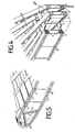
- the stability of the ribs 8 is in no way impaired by the fact that between the cross plates 10, as indicated in FIGS. 3, 4 and 5, angular joints consist. These come about because the longitudinal strips 9 are slightly curved and the ribs 8 assume a parabolic curvature in the longitudinal direction.
- FIG. 5 shows a part of the structure of a segment on the outer edge in more detail.
- the longitudinal struts 3 of the top of the double shell are bent around an angular spar 11 towards the longitudinal struts of the bottom. This creates a bead-shaped outer edge which, in conjunction with the supporting frame, enables the parabolic mirror to be covered with a radiation-permeable material without damage.
- a mounting point of the support frame can be provided above the focal point of the parabolic mirror. At this attachment point a spider is attached, the arms of which are attached to the bars of the mirror edge. In this way, the parabolic mirror can be enveloped by the radiation-permeable material and thus be protected from the weather.
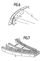
- Fig. 6 the mirror edge is shown, which consists of the angular spar 11.
- the angular spars of the segments 1 can be screwed to the horizontal brackets 4 and the vertical brackets 12 of the mirror edge, as a result of which the intended shape of the parabolic mirror consists of several segments 1.
- the teaching scaffold shown in FIG. 7 is provided. It consists of longitudinal beams 14 for receiving one rib 8 each and combs 13 for positioning the cross struts 2.
- the longitudinal beams 14 are in turn formed from ribs 8.
- the ribs 8 are then connected to each other with the help of the combs 13 by the cross struts 2.
- the longitudinal struts 3 are then attached to the cross struts 2. Finally, the strips 6 of the reflective layer are applied.
- the advantage of the demountable parabolic mirror described above is that it can be manufactured inexpensively from parts that are easy and quick to manufacture, but nevertheless stably and effectively.
- Foil mirrors seem to be cheaper. In reality, the savings are small here too, considering the stable construction for the rigid support ring for the film; the support ring itself must also be adjusted. In addition, with films only mirrors with a large focal length, i.e. low curvature are to be produced, otherwise the deviations of the chain line from the desired parabolic shape will be too large. A large focal length, however, means that the converter for the radiation is located far away and the support ring must also absorb huge torques. The task is therefore to create a parabolic mirror that can be dismantled, which consists of inexpensive, easily manufactured and machinable parts and is nevertheless extremely stable.
Landscapes
- Physics & Mathematics (AREA)
- Engineering & Computer Science (AREA)
- Life Sciences & Earth Sciences (AREA)
- Sustainable Development (AREA)
- Thermal Sciences (AREA)
- Optics & Photonics (AREA)
- General Physics & Mathematics (AREA)
- Sustainable Energy (AREA)
- Astronomy & Astrophysics (AREA)
- Chemical & Material Sciences (AREA)
- Combustion & Propulsion (AREA)
- Mechanical Engineering (AREA)
- General Engineering & Computer Science (AREA)
- Electromagnetism (AREA)
- Aerials With Secondary Devices (AREA)
- Optical Elements Other Than Lenses (AREA)
Applications Claiming Priority (2)
| Application Number | Priority Date | Filing Date | Title |
|---|---|---|---|
| DE8412066U DE8412066U1 (de) | 1984-04-13 | 1984-04-13 | Zerlegbarer Parabolspiegel zur Konzentrierung von Strahlung |
| DE8412066U | 1984-04-13 |
Publications (2)
| Publication Number | Publication Date |
|---|---|
| EP0170610A2 true EP0170610A2 (fr) | 1986-02-05 |
| EP0170610A3 EP0170610A3 (fr) | 1986-12-30 |
Family
ID=6766022
Family Applications (1)
| Application Number | Title | Priority Date | Filing Date |
|---|---|---|---|
| EP85730058A Withdrawn EP0170610A3 (fr) | 1984-04-13 | 1985-04-12 | Miroir parabolique démontable pour concentrer des rayons |
Country Status (2)
| Country | Link |
|---|---|
| EP (1) | EP0170610A3 (fr) |
| DE (1) | DE8412066U1 (fr) |
Family Cites Families (8)
| Publication number | Priority date | Publication date | Assignee | Title |
|---|---|---|---|---|
| US2997712A (en) * | 1957-06-14 | 1961-08-22 | Donald S Kennedy | Antenna reflector construction |
| FR1493600A (fr) * | 1966-06-27 | 1967-09-01 | Structure applicable à la fabrication des réflecteurs d'ondes démontables de précision concaves, plans ou convexes | |
| US3832717A (en) * | 1972-03-03 | 1974-08-27 | R Taggart | Dish reflector for a high gain antenna |
| CH610115A5 (en) * | 1976-04-05 | 1979-03-30 | Baum Erich | Concave mirror simulator |
| US4226506A (en) * | 1978-04-10 | 1980-10-07 | Saint-Gobain Industries | Swiveling solar reflector with multiple reflecting elements supported by prefabricated cambered members |
| EP0025834A3 (fr) * | 1979-09-25 | 1981-04-29 | Reymont Bertrand | Collecteur de l'énergie solaire avec un élément réfléchissant parabolique |
| US4416262A (en) * | 1980-07-22 | 1983-11-22 | Niedermeyer William P | High ratio microwave energy concentrating collector |
| US4340031A (en) * | 1980-07-22 | 1982-07-20 | Niedermeyer William P | High ratio solar energy concentrating collector |
-
1984
- 1984-04-13 DE DE8412066U patent/DE8412066U1/de not_active Expired
-
1985
- 1985-04-12 EP EP85730058A patent/EP0170610A3/fr not_active Withdrawn
Also Published As
| Publication number | Publication date |
|---|---|
| EP0170610A3 (fr) | 1986-12-30 |
| DE8412066U1 (de) | 1985-08-14 |
Similar Documents
| Publication | Publication Date | Title |
|---|---|---|
| DE19744767C2 (de) | Parabolrinnenkonzentrator | |
| DE3216845C2 (fr) | ||
| EP1586124A2 (fr) | Collecteur solaire | |
| DE3734373C1 (de) | Leichtbauelement mit von wabenfoermigen Hohlkoerpern auf Distanz gehaltenen Deckplatten | |
| DE3130471C2 (de) | Spiegelanordnung zum Reflektieren und Konzentrieren von Strahlungsenergie | |
| DE2904648A1 (de) | Sonnenkollektor | |
| EP3126754B1 (fr) | Héliostat à symétrie centrale et centrale solaire comportant un récepteur et une pluralité d'héliostats | |
| EP0050697B1 (fr) | Réflecteur à concentration pour radiation solaire à basse résistance aérodynamique et à haute portance aérodynamique | |
| DE202010018255U1 (de) | Parabolrinne für Solarkollektoren und Stützvorrichtung dafür | |
| DE202009017657U1 (de) | Vorrichtung, insbesondere Heliostat | |
| EP0170610A2 (fr) | Miroir parabolique démontable pour concentrer des rayons | |
| DE2232114B2 (de) | Kuppeiförmiges Gebäude | |
| DE3030033C2 (fr) | ||
| DE2935341A1 (de) | Reflektor | |
| EP2302307B1 (fr) | Miroir de précision doté de rainures collées | |
| DE102016009577A1 (de) | Reflektor für die Konzentration von Solarstrahlung | |
| AT519240B1 (de) | Vorrichtung zum Erwärmen eines Wärmeträgers | |
| DE2711307A1 (de) | Konvergenzspiegel, insbesondere fuer sonnenkraftanlagen und verfahren zu seiner herstellung | |
| WO2018234171A1 (fr) | Facette pour un héliostat de type sandwich et procédé pour la fabrication d'une facette | |
| EP3882410B1 (fr) | Nouvelles liaisons nodales de face avant pour structures porteuses planes | |
| DE8716964U1 (de) | Bauelement | |
| DE3131263C1 (de) | Verfahren zur Herstellung eines gekrümmten Reflektors | |
| DE2901002A1 (de) | Verbesserung an sonnenstrahlenreflektoren | |
| DE1619715C3 (de) | Aus Bauteilen bestehende Waschoder Rektifiziersäulen | |
| DE2447820A1 (de) | Wuerfelelement |
Legal Events
| Date | Code | Title | Description |
|---|---|---|---|
| PUAI | Public reference made under article 153(3) epc to a published international application that has entered the european phase |
Free format text: ORIGINAL CODE: 0009012 |
|
| AK | Designated contracting states |
Kind code of ref document: A2 Designated state(s): AT BE CH DE FR GB IT LI LU NL SE |
|
| PUAL | Search report despatched |
Free format text: ORIGINAL CODE: 0009013 |
|
| AK | Designated contracting states |
Kind code of ref document: A3 Designated state(s): AT BE CH DE FR GB IT LI LU NL SE |
|
| 17P | Request for examination filed |
Effective date: 19870828 |
|
| 17Q | First examination report despatched |
Effective date: 19881129 |
|
| STAA | Information on the status of an ep patent application or granted ep patent |
Free format text: STATUS: THE APPLICATION IS DEEMED TO BE WITHDRAWN |
|
| 18D | Application deemed to be withdrawn |
Effective date: 19901017 |
|
| RIN1 | Information on inventor provided before grant (corrected) |
Inventor name: RADEBOLD, REINHART, DR. |