EP0170722A2 - Dispositif de fixation pour monture de lunettes - Google Patents
Dispositif de fixation pour monture de lunettes Download PDFInfo
- Publication number
- EP0170722A2 EP0170722A2 EP84113070A EP84113070A EP0170722A2 EP 0170722 A2 EP0170722 A2 EP 0170722A2 EP 84113070 A EP84113070 A EP 84113070A EP 84113070 A EP84113070 A EP 84113070A EP 0170722 A2 EP0170722 A2 EP 0170722A2
- Authority
- EP
- European Patent Office
- Prior art keywords
- bore
- leg
- pin
- projection
- spectacle lens
- Prior art date
- Legal status (The legal status is an assumption and is not a legal conclusion. Google has not performed a legal analysis and makes no representation as to the accuracy of the status listed.)
- Granted
Links
- 238000004873 anchoring Methods 0.000 claims abstract description 23
- 239000011521 glass Substances 0.000 claims description 56
- 239000004033 plastic Substances 0.000 claims description 5
- 229920003023 plastic Polymers 0.000 claims description 5
- 239000012858 resilient material Substances 0.000 claims description 3
- 230000007704 transition Effects 0.000 claims description 2
- 239000007779 soft material Substances 0.000 claims 2
- 230000000284 resting effect Effects 0.000 claims 1
- 210000002414 leg Anatomy 0.000 description 31
- 210000003128 head Anatomy 0.000 description 13
- 239000000463 material Substances 0.000 description 6
- 238000006073 displacement reaction Methods 0.000 description 3
- 239000000853 adhesive Substances 0.000 description 2
- 230000001070 adhesive effect Effects 0.000 description 2
- 230000015572 biosynthetic process Effects 0.000 description 2
- 230000000694 effects Effects 0.000 description 2
- 239000013013 elastic material Substances 0.000 description 2
- 238000004519 manufacturing process Methods 0.000 description 2
- 230000001154 acute effect Effects 0.000 description 1
- 230000006978 adaptation Effects 0.000 description 1
- 230000002411 adverse Effects 0.000 description 1
- 238000005452 bending Methods 0.000 description 1
- 230000006835 compression Effects 0.000 description 1
- 238000007906 compression Methods 0.000 description 1
- 238000012937 correction Methods 0.000 description 1
- 230000002349 favourable effect Effects 0.000 description 1
- 229910052500 inorganic mineral Inorganic materials 0.000 description 1
- 239000007769 metal material Substances 0.000 description 1
- 239000011707 mineral Substances 0.000 description 1
- 238000007789 sealing Methods 0.000 description 1
- 239000005368 silicate glass Substances 0.000 description 1
- 210000000689 upper leg Anatomy 0.000 description 1
Images

Classifications
-
- G—PHYSICS
- G02—OPTICS
- G02C—SPECTACLES; SUNGLASSES OR GOGGLES INSOFAR AS THEY HAVE THE SAME FEATURES AS SPECTACLES; CONTACT LENSES
- G02C1/00—Assemblies of lenses with bridges or browbars
- G02C1/04—Bridge or browbar secured to or integral with partial rims, e.g. with partially-flexible rim for holding lens
-
- G—PHYSICS
- G02—OPTICS
- G02C—SPECTACLES; SUNGLASSES OR GOGGLES INSOFAR AS THEY HAVE THE SAME FEATURES AS SPECTACLES; CONTACT LENSES
- G02C1/00—Assemblies of lenses with bridges or browbars
- G02C1/02—Bridge or browbar secured to lenses without the use of rims
Definitions
- the invention relates to glasses with a fastening device according to the preamble of claim 1.
- the spectacle glass is supported on the half beam in the middle of the sleeve, but the sleeve provides a certain distance, so that the curvature of the surface of the spectacle glass facing the half beam does not determine the relative position between the half beam and the spectacle glass.
- a sufficiently rigid connection is not achieved in this known manner, however, since the elastic ring provided for adapting to different curvatures of the surface of the spectacle glass facing away from the half beam inevitably still permits certain relative movements between the spectacle glass and the half beam.
- this known type of attachment allows a relative rotation between the half-bar and the lens around the axis of the threaded pin. For this reason, two such fastening devices are provided for each BriLLengLas in the known case.
- the known fastening device is not suitable for the connection between a bridge or jaw on the one hand and a BriLLengLas on the other hand with the help of only one pin, which must be relatively stiff.
- the invention is based on the object of developing the generic spectacles in such a way that the connection between the individual part and the spectacle lens is as rigid and reliable as possible even when only a pen is used.
- Differently curved front sides and differently curved rear sides as well as different thicknesses of the spectacle lens should have as little influence as possible in the edge region thereof on the design of the fastening device and require as little adjustment work as possible.
- the BriLLengLas is not supported directly with its front or back on the leg, but the BriLLengLas is clamped between the connecting element and the first projection.
- the projection and the connecting element engage on the surfaces of the two bore extensions, so that it is no longer the curvature and the course of the side of the spectacle lens facing the leg that determine the orientation of the individual part relative to the spectacle lens, but this alignment is determined by the bore extensions.
- Different thicknesses in the edge region of the spectacle lens can be taken into account by forming one or both bore extensions to different depths and / or by corresponding length of the pin.
- the clamping of the glasses between the connecting element and the projection and the force application of the connecting element and the projection on the surfaces of two bore extensions lead to a rigid and firm connection between the leg or individual part in the longitudinal direction of the pin and against rotations around the longitudinal axis of the Pen's vertical axes.
- the anti-rotation against rotation about the longitudinal axis of the pin consists of the second projection and the third projection, both of which engage on the edge of the lens and in this way have a relatively large distance from the longitudinal axis of the pin, so that they are relatively against rotation about this axis cause a large counter moment.
- the second and the third projection form a four-point bearing or support for the spectacle lens and the individual part relative to one another.
- This fastening device can be used unchanged for numerous different spectacle lenses, since the differences between the spectacle lenses can be taken into account due to the design of the bore extensions on them and, if applicable, due to the length of the pin
- the surfaces of the two bore extensions are spherical sections and that the connecting element has an overall spherical shape and is formed in one piece with the pin. This makes it possible to make the diameter of the connecting element only slightly larger than the diameter of the pin and yet to ensure a sufficiently large contact area between the connecting element and the associated bore extension.
- the design of the connecting element which is also rounded to the outside, matches the appearance of any curvature of the spectacle lens side on which the connecting element is located, so that it is preferably arranged on the front face of the spectacle lens without impairing the appearance of the spectacle lens.
- the pin and the leg are formed separately from one another and the connection between the opening provided for the pin in the leg and the associated end section of the pin is a connection which can be brought about by plugging in or pushing in, for example a adhesive connection or a snap connection.
- a connection which can be brought about by plugging in or pushing in, for example a adhesive connection or a snap connection.
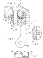
- FIGS. 1 to 3 The first embodiment is first explained in more detail below with reference to FIGS. 1 to 3.
- a jaw 2 can be seen, which is connected to an eyeglass lens 4 of an eyeglass by means of a fastening device to be described in more detail, of which further elements are not shown.
- the jaw 2 which can also be referred to as a bend joint piece, is selected here as an individual part, on the basis of which the invention is explained.
- the following description of the exemplary embodiments serves analogously for all individual parts to be connected with a spectacle lens, that is to say in particular also for a bridge.
- the spectacle lens shown is a plus lens with a curved front 6 and a curved rear 8, the curvatures of the front 6 and the rear 8 being different.
- Radially outside, the BriLLengLas 4 is delimited by an edge 10 which merges into a front edge 12 and a rear edge 14 into the front side 6 and the rear side 8, bevels 16 and 18 being provided on the edges in the manner shown.
- the spectacle lens 4 is associated with a spectacle lens plane which can be defined, for example, by the rear edge 14 and to which the edge 10 runs essentially perpendicular.
- the material of the BriLLengLase 4 can be both a plastic glass and a mineral glass, for example a silicate glass.
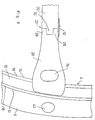
- the jaw 2 connects the spectacle lens 4 to a bracket 20 (see FIG. 4), a joint 22 being formed between the bracket 20 and the jaw 2.
- the individual part in the form of the jaw 2 comprises a leg 24 running essentially parallel to the plane of the spectacle lens, which is formed in one piece with an arm 26 running essentially perpendicularly to the plane of the spectacle lens to the rear, ie downwards in FIG. 1, on the lower end of which in FIG. 2 two joint eyes 28 of the joint 22 are formed.
- the hinge 22 is completed by a further hinge eye 30 formed on the hanger 20 and a hinge pin 32 (see FIG. 4). At the end of the arm 26 facing away from the hinge eyes 28, this arm points forward over the leg 24 (or above in FIG. 1) above extension 34.
- This extension extends approximately to the front edge 12 of the BriLLeng glass.
- the arm 26 has its greatest height approximately in the region of the leg 24.
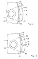
- the SchenkeL24 the outline of which can be seen in broken lines in FIG. 2, has an essentially triangular shape when viewed in FIG. 2, and tapers away from the arm 26.
- the leg 24 On its side facing the spectacle lens 4, the leg 24 has an essentially flat surface 36 which essentially encloses a right angle with the inside 38 of the extension 34 (see FIG. 1).
- the fastening device which connects the eyeglass 14 to the individual part in the form of the jaw 2 comprises a straight pin 40 which is formed in one piece on its front end section 41, which is upper in FIG. 1, with a connecting element 42 which has the shape of a ball.
- a cylindrical bore 44 is formed near the edge 10 thereof, which leads from the front 6 to the rear 8 of the spectacle lens 4.
- this has a rotationally symmetrical first bore extension which is concentric with the bore axis. 46 in which the connecting element 42 is seated.
- the two contacting surfaces of the first hole extension 46 and the connecting element 42 are each spherical surface sections.
- the free surface of the connecting element 42 is also a spherical surface section. In the illustrated embodiment, this is visible on the front 6 of the BriLLengLase 4, over which it protrudes somewhat.
- the cylindrical pin 40 runs through the bore 44 and is fastened to the leg 24 with its second end section 48, which is lower in FIG. 1.
- the SchenkeL 24 has a cylindrical, straight opening 50 with a smooth surface.
- the opening 50 is designed as a through-opening, so that it is open on the underside of the leg 24, which faces away from the rear side 8 of the spectacle lens 4.
- clamp connections screw connections in which both the second end section 48 and the opening 50 are provided with corresponding threads
- clamp connections and snap-in connections are possible. The latter possibility is chosen in the exemplary embodiment according to FIGS. 1 to 4.
- the second end section 48 is provided with latching projections 52 (see FIG. 3), whereas the opening 50 has a smooth surface.
- the dimensions of the opening 50 and the second end section 48 with its circumferential locking projections 52 are selected such that the locking projections 52 press into the smooth surface of the opening 50 and the material of the leg 24 flows cold, so that after the pin 40 has been inserted into the opening 50, a positive connection is obtained after a certain time.
- This enables the pin 40 to be fastened to the leg 24 in any axial position, that is to say steplessly.
- the end of the pin 40 protruding from the opening 50 at the second end section 48 is cut off such that there is a smooth transition to the underside of the leg 24.
- a first projection 54 is formed integrally thereon concentrically to the opening.
- the surface of the first projection 54 forms a spherical surface section.
- the bore 44 in the BriLLengLas 4 is expanded at the end facing the leg 24 to a second bore extension 56 which is concentric and rotationally symmetrical to the axis of the bore 44.
- the surface of the second bore extension is a spherical surface section, the surface of the second bore extension 56 and the surface of the first projection 54 lying concentrically to one another at a short distance from one another.
- a thin intermediate layer 58 made of elastic material is arranged between these two surfaces, so that the first projection 54 and the second bore widening 56 in the exemplary embodiment shown are supported against one another indirectly via the intermediate layer 58, although direct support is possible if the intermediate layer 58 is omitted.
- a second projection 60 in the form of a strip and a third projection 62 in the form of a strip are formed on the extension 34.
- the Both projections 60 and 62 lie - when viewed in the circumferential direction of the BriLLengLase 4 - at one or the other end of the projection 34.
- the edge 10 of the BriLLengLase 4 has a point A closest to the bore 44
- the second projection 60 is arranged on one side and the third projection 62 on the other side (when viewed in the circumferential direction of the spectacle lens 4).
- the strips forming the second and third protrusions run approximately perpendicular to the plane of the spectacle lens and lie with an edge at the edge 10.
- the inside 38 of the projection 34 has a certain distance from the edge 10 in the exemplary embodiment shown. However, it could also run directly along the edge between the two projections 60 and 62; it is also possible for the second projection and the third projection to be supported indirectly at the edge 10 via an elastic intermediate layer similar to the intermediate layer 58.
- Such an elastic intermediate layer like the intermediate layer 58, would serve to prevent stress concentrations in the contact area of the elements or parts abutting one another and to ensure an equalization of the load.
- the spectacle lens 4 is additionally supported with its edge 14 on the leg 24, specifically on its surface 36. This support is indirect because there is still between the edge 14 and the surface 36 there is a further intermediate layer 64 made of soft, elastic material, which together with the intermediate layer 58 forms an intermediate layer.
- the glasses designed as described above are assembled in the following manner.
- the bore 44 is first formed, the position of which with respect to the edge 10 is predetermined by the position of the opening 50 in the leg 24 relative to the second projection 60 and the third projection 62.
- the axes of the bore 44 and the opening 50 coincide in the exemplary embodiment shown, these axes can also be offset and / or intersect parallel to one another, since the desired orientation (opening angle and angle of inclination) relative to the spectacle lens 4 or the spectacle lens plane essentially through the bore extensions 46 and 56 is determined.
- the second bore extension 56 is formed, the curvature of the rear side 8 of the spectacle lens 4 being taken into account when the bore extension 56 is formed.
- the second bore extension 56 in the spectacle lens 4 produces a deeper recess than if the rear side is more curved and has the course shown with solid lines (rear side 8) .
- this means that the second bore extension 56 in the spectacle lens 4 is designed such that it has a different position with respect to this rear face 8 depending on the course and curvature of the rear face of the spectacle lens, but always has the same position with respect to the leg 24 (for a certain opening angle).
- the first bore extension 46 is formed at the front end of the bore 44.
- a certain protrusion of the connecting element 42 over the front side 6 can be predetermined in the region of the bore 4, regardless of the thickness of the spectacle lens 8; but it can also have a certain length of the bore 44 be specified between the two bore extensions, so that the first bore extension 46 is then deeper for thicker BriLLeng glasses and flatter for thinner glasses.
- the BriLLengLas After the BriLLengLas has been formed with the bore 44 and its two bore extensions 46 and 56, the BriLLengLas is placed on the jaw 2 in such a way that the relative position shown in FIGS. 1, 2 and 4 is obtained, the intermediate support being interposed from the intermediate layers 58 and 64 becomes. Then the pin 41 is then inserted from the front 6 of the lens 4 into the bore 44 and the opening 50. (However, the pin 40 can also be inserted into the bore 44 first, before the pin 40 together with the BriLLengLas 4 is brought into connection with the jaw 2.) The pin 40 is pressed so far into the opening 50 that the BriLLengLas 42 is clamped free of play between the connecting element 42 and the first projection 54 with a certain compression of the two intermediate layers 58 and 64. The end of the pin 40 protruding from the opening 50 below is then removed.
- the spectacle lens 4 and the jaw 2 are fixed relative to one another in the direction of the axis of the pin 40.
- This clamping also prevents any relative rotation between the jaw 2 and the BriLLengLas 4 about an axis perpendicular to the latter axis.
- This attachment is achieved without the curvatures of the front 6 and rear 8 can have an adverse effect. Neither does the curvature of the rear side 8 determine the course of the leg 24 and thus the opening angle of the glasses, nor does the curvature of the front side 6 cause the pin 40 to bend or even an eccentric point contact of the connecting element 42 with the BriLLengLas 4.
- the rotation about the axis of the pin 40 or the opening 50 which has not yet been prevented by the above-described clamping between the connecting element 42 and the first projection 54, is prevented by the anti-rotation device in the form of the second projection 60 and the third projection 62, which due to their relatively large distance from the latter axis can counter a rotation about this a significant moment.
- the fastening device described thus forms with the three projections 54, 60 and 62 and the connecting element 42 a four-point bearing for the spectacle lens 4 on the jaw 2 or vice versa. Through the additional support of the edge 14 on the jaw 2, the entire connection described above is tensioned, which leads to a certain bending stress on the pin 40 and thereby stiffens the unit consisting of the jaw 2 and BriLLengLas 4.
- the intermediate support formed from the two intermediate layers 58 and 64 is provided which, since it is made of an elastically flexible material, prevents stress concentrations and thus has the function of a cushion and can also be referred to as such.
- this intermediate layer can be used to influence the alignment of the spectacle glass 4 relative to the component in the form of the jaw 2.
- the actual contact between the first projection 54 and the bore extension 56 takes place on the surface of the intermediate layer 58.
- the distance at which the projection 54 supports the projection lens 4 on the bore extension 56 depends on the position of the above-mentioned surface of the intermediate layer 58.
- intermediate layers can now be used, which have different thicknesses in the area of the intermediate layer 58 in the direction of the axis of the bore 50.
- Such an intermediate layer is shown in FIG. 9, which is thicker in the area of the intermediate layer 58 than the intermediate layer shown in FIG. 1.
- the intermediate support shown in FIG. 9 has a further intermediate layer 84, which is arranged in the assembled state between the second and third protrusions 60 and 62 on the one hand and the edge 10 of the BriLLeng glass 4 on the other hand, as already described above as Possibility is indicated. If the intermediate support shown in FIG. 9 were used instead of the intermediate support shown in FIG.
- This possibility of influencing with the aid of the intermediate support or the cushion can be used in particular to fix the core of the projection 54 on Form leg 24 relatively flat and to bring the desired height or extension in the direction of the axis of the bore 50 through the intermediate support.
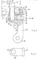
- FIGS. 5 to 8 The exemplary embodiment according to FIGS. 5 to 8 is explained below, which partially corresponds to the exemplary embodiment described above. As far as the correspondence is sufficient, the same reference numerals are used for the same elements of the second exemplary embodiment as in the first exemplary embodiment and the second exemplary embodiment is not explained again. In the following, therefore, only those features of the second exemplary embodiment are described which distinguish it from the first.
- the jaw 2 comprises an anchoring part 66 which essentially has the shape of an elongated cuboid (see FIG. 7).
- This anchoring part 66 sits in a groove 68 of the jaw 2, the groove base of which runs essentially parallel to the lens plane.
- the groove 68 is open to the rear 8 of the BriLLengLase 4 and to the left (in FIG. 5).
- the opening 50 is formed for receiving the second end section 48 of the pin 41.
- the function of the anchoring part 66 is that the pin 41 is anchored directly to it and that by attaching the anchoring part 66 to the other jaw 2, the pin 41 is indirectly attached to the rest of the individual part in the form of the jaw 2.
- the second end section 48 of the pin 41 can be fastened in the opening 50 in any desired manner, for example as described for the first exemplary embodiment.
- a riveted connection is provided in the second exemplary embodiment according to FIGS. 5 to 8, a riveted connection is provided.
- the opening 50 is designed as a smooth through hole and the free end of the pin 41 is flattened to form a rivet head 70.
- a recess 72 is formed in the leg 24 which is large enough to accommodate the rivet head 70 when the anchoring part 66 is seated in its groove 68.
- a latching connection which comprises a latching head 74 formed at the right end of the anchoring part 66 in FIG. 7 as well as a latching hole 76 in the arm 26 adapted to this.
- the latching hole 76 has a circumferential shoulder 78, which can come into engagement with the underside of the locking head 74 and thereby prevent the anchoring part 66 from shifting to the left in FIG. 5, as soon as the locking head 74 has been pushed so far to the right in FIG. 5 that the shoulder 78 engages behind.
- the first. Projection 54 is formed directly on the leg 24, in the second exemplary embodiment according to FIGS. 5 to 8 it is formed separately therefrom. Furthermore, in the second exemplary embodiment, the second projection 60 and the third projection 62 are not formed directly on the extension 34, but rather formed as ends of a small plate 80 which runs along the edge 10 adjacent to this.
- the plate 80 is formed in one piece with the first projection 54 and, together with it, forms a separate component 82 that is supported on the one hand to the right (in FIG. 5) on the extension 34 and on the other hand downwards (in FIG. 5) on the leg 24, to which the anchoring part 66 belongs.
- the component 82 can be made from an elastically resilient material in a manner similar to the intermediate layer consisting of the intermediate layers 58 and 64 and possibly 84 of the first exemplary embodiment and then at the same time fulfill the cushioning function of the intermediate layer of the first exemplary embodiment.
- the strength of the resilient material is preferably chosen from the point of view that there is sufficient softness on the one hand to compensate for manufacturing tolerances and inaccuracies and to prevent stress peaks, and on the other hand that the dimensional stability is sufficient even in the assembled state to ensure a sufficiently rigid connection between the BriLLengLas and to ensure the component. In practice, this can mean that a thin and / or small lens that is light in weight uses a softer material than thicker and / or larger lens that is heavier. This information on the material also applies accordingly to the intermediate edition of the first embodiment.
- the spectacle glass 4 and the anchoring part 66 are first put together with the component 82 interposed and firmly attached to one another with the aid of the pin 41 which is connected, the pin 41 being provided with the rivet head 70. Then the unit created in this way, consisting of the glass 4, the pin 41, the anchoring part 66 and the component 82, is then joined to the rest of the jaw by inserting the anchoring part 66 into the groove 68 and as far to the right (in FIG. 5) is pressed until the locking head 74 has engaged the locking hole 76.
- This connection between the anchoring part 66 and the rest of the jaw can additionally be secured by adding adhesive.
- the pin 41 can be anchored in the opening 50 unhindered by other elements of the individual part or the jaw 2.
- the leg 24 and the arm 26 must leave sufficient space to be able to remove the protruding end of the second end section 48.
- This need does not exist in the second exemplary embodiment according to FIGS. 5 to 8.
- the individual part or the jaw 2 can be designed without having to keep space in the area of the free end of the second end section.
- the axes of the pin 40 and the opening 50 on the one hand and the axis of the bore 44 on the other hand do not have to coincide. Rather, they can also enclose an acute angle and / or be offset in parallel relative to one another.
- the bore 44 can have a larger diameter than the end section 41, as can also be seen in FIG. 5. Such an oversize is even preferable so that the pin 40 can adjust freely within the bore 44 within certain limits.
- the bore extensions 46 and 56 also need not be designed concentrically to the bore axis of the bore 44. Rather, they can also be designed eccentrically with respect to this bore axis, as is shown in the second exemplary embodiment in FIG.
- the extent and the direction of the eccentricity can influence the orientation of the component relative to the spectacle lens.
- a displacement of the bore extension 56 to the right in FIG. 5 relative to the bore extension 56 shown there and thus relative to the axis of the bore 44 would result in a larger opening angle, while a displacement in the opposite direction would result in a smaller opening angle would lead.
- a displacement of the bore extension 56 perpendicular to the plane of the drawing from the illustrated position of the bore extension 56 would change the inclination angle in a corresponding manner.
- plastics are both plastics and - with the exception of the elastic intermediate support of the first embodiment and the possibly also elastic component 82 of the second embodiment - metallic materials.
- plastics are preferably used exclusively.
Landscapes
- Physics & Mathematics (AREA)
- Health & Medical Sciences (AREA)
- General Physics & Mathematics (AREA)
- Ophthalmology & Optometry (AREA)
- Optics & Photonics (AREA)
- Eyeglasses (AREA)
- Finger-Pressure Massage (AREA)
- Helmets And Other Head Coverings (AREA)
- Gripping Jigs, Holding Jigs, And Positioning Jigs (AREA)
- Eye Examination Apparatus (AREA)
Priority Applications (1)
| Application Number | Priority Date | Filing Date | Title |
|---|---|---|---|
| AT84113070T ATE43922T1 (de) | 1984-08-07 | 1984-10-30 | Brille mit einer befestigungsvorrichtung. |
Applications Claiming Priority (2)
| Application Number | Priority Date | Filing Date | Title |
|---|---|---|---|
| DE3429071 | 1984-08-07 | ||
| DE3429071A DE3429071C2 (de) | 1984-08-07 | 1984-08-07 | Brille mit einer Befestigungsvorrichtung |
Publications (3)
| Publication Number | Publication Date |
|---|---|
| EP0170722A2 true EP0170722A2 (fr) | 1986-02-12 |
| EP0170722A3 EP0170722A3 (en) | 1987-02-04 |
| EP0170722B1 EP0170722B1 (fr) | 1989-06-07 |
Family
ID=6242533
Family Applications (1)
| Application Number | Title | Priority Date | Filing Date |
|---|---|---|---|
| EP84113070A Expired EP0170722B1 (fr) | 1984-08-07 | 1984-10-30 | Dispositif de fixation pour monture de lunettes |
Country Status (9)
| Country | Link |
|---|---|
| US (1) | US4685781A (fr) |
| EP (1) | EP0170722B1 (fr) |
| JP (1) | JPS6147925A (fr) |
| KR (1) | KR880002449B1 (fr) |
| AT (1) | ATE43922T1 (fr) |
| BR (1) | BR8503712A (fr) |
| CA (1) | CA1267007A (fr) |
| DE (2) | DE3429071C2 (fr) |
| SU (1) | SU1508974A3 (fr) |
Cited By (3)
| Publication number | Priority date | Publication date | Assignee | Title |
|---|---|---|---|---|
| EP0601849A1 (fr) * | 1992-12-08 | 1994-06-15 | Kabushiki Kaisha Takeda | Lunettes sans monture |
| FR2715235A1 (fr) * | 1994-01-17 | 1995-07-21 | Timon | Dispositif de fixation de verres de lunettes sur un élément de monture tel que pont ou branche, et paire de lunettes réalisée avec un tel dispositif. |
| WO1996025684A1 (fr) * | 1995-02-17 | 1996-08-22 | Fabienne Coudray Meisel | Monture de verres de lunettes |
Families Citing this family (7)
| Publication number | Priority date | Publication date | Assignee | Title |
|---|---|---|---|---|
| DE4217908C1 (en) * | 1992-05-29 | 1993-01-21 | Optische Werke G. Rodenstock, 8000 Muenchen, De | Spectacle lens fastener system - includes screw with tapered head expanding end of frame member fitting into bore in lens |
| US5406337A (en) * | 1992-11-24 | 1995-04-11 | Cabot Safety Corporation | Semi-rimless eyeglass frame assembly |
| US5412440A (en) * | 1992-12-08 | 1995-05-02 | Kabushiki Kaisha Takeda | Rimless spectacles with adjustable temples and lenses |
| DE10151463B4 (de) * | 2001-10-18 | 2013-03-28 | Eye-Systems Gmbh | Randlose Brille |
| KR200385176Y1 (ko) * | 2005-01-14 | 2005-05-25 | 임언수 | 무테안경 |
| DE102005026260B4 (de) * | 2005-05-04 | 2007-05-16 | Guenther Wied | Vorrichtung zum Wechseln von Bügeln, Backen und Steg für Randlosbrillen sowie Bügeln und Backen für Metall- und Kunststoff-Brillengestelle |
| US7726808B1 (en) | 2009-05-20 | 2010-06-01 | Gentex Optics, Inc. | Rimless spectacle lens bore polishing method and apparatus |
Family Cites Families (13)
| Publication number | Priority date | Publication date | Assignee | Title |
|---|---|---|---|---|
| CH13336A (de) * | 1896-11-03 | 1897-06-30 | Interchangeable Frameless Spec | Haltekloben mit Befestigungsvorrichtung für Brillen und Klemmer ohne Randeinfassung |
| US1982047A (en) * | 1933-04-04 | 1934-11-27 | Ralph L Dublin | Eyeglass and spectacle mounting |
| US2173670A (en) * | 1936-12-28 | 1939-09-19 | American Optical Corp | Ophthalmic mounting and method of making same |
| US2328423A (en) * | 1938-06-29 | 1943-08-31 | American Optical Corp | Ophthalmic mounting |
| US2328708A (en) * | 1938-06-29 | 1943-09-07 | American Optical Corp | Ophthalmic mounting |
| US2389116A (en) * | 1944-01-13 | 1945-11-20 | Bausch & Lomb | Ophthalmic mounting |
| DE2136802C3 (de) * | 1971-07-23 | 1979-01-11 | Marwitz & Hauser, 7000 Stuttgart | Randlose Brille |
| DE7614516U1 (de) * | 1976-05-07 | 1977-04-21 | Erwa-Optik A. Roos, 7530 Pforzheim | Glashalterung fuer randlose brillen |
| JPS537253A (en) * | 1976-07-08 | 1978-01-23 | Seijirou Horikawa | Sidepieces of eyeglasses and method of fixing bridge and lens |
| JPS5628566Y2 (fr) * | 1977-02-25 | 1981-07-07 | ||
| US4187007A (en) * | 1978-09-18 | 1980-02-05 | Martin-Copeland Company | Eyeglass construction |
| US4245896A (en) * | 1978-10-24 | 1981-01-20 | Kaplan Michael A | Spectacles |
| JPS56126610U (fr) * | 1980-02-18 | 1981-09-26 |
-
1984
- 1984-08-07 DE DE3429071A patent/DE3429071C2/de not_active Expired
- 1984-10-30 AT AT84113070T patent/ATE43922T1/de not_active IP Right Cessation
- 1984-10-30 EP EP84113070A patent/EP0170722B1/fr not_active Expired
- 1984-10-30 DE DE8484113070T patent/DE3478646D1/de not_active Expired
- 1984-11-20 US US06/873,518 patent/US4685781A/en not_active Expired - Fee Related
-
1985
- 1985-06-28 CA CA000485977A patent/CA1267007A/fr not_active Expired - Lifetime
- 1985-08-06 SU SU853931623A patent/SU1508974A3/ru active
- 1985-08-06 BR BR8503712A patent/BR8503712A/pt not_active IP Right Cessation
- 1985-08-06 JP JP60173064A patent/JPS6147925A/ja active Granted
- 1985-08-07 KR KR1019850005697A patent/KR880002449B1/ko not_active Expired
Cited By (4)
| Publication number | Priority date | Publication date | Assignee | Title |
|---|---|---|---|---|
| EP0601849A1 (fr) * | 1992-12-08 | 1994-06-15 | Kabushiki Kaisha Takeda | Lunettes sans monture |
| FR2715235A1 (fr) * | 1994-01-17 | 1995-07-21 | Timon | Dispositif de fixation de verres de lunettes sur un élément de monture tel que pont ou branche, et paire de lunettes réalisée avec un tel dispositif. |
| WO1996025684A1 (fr) * | 1995-02-17 | 1996-08-22 | Fabienne Coudray Meisel | Monture de verres de lunettes |
| FR2730825A1 (fr) * | 1995-02-17 | 1996-08-23 | Coudray Meisel Fabienne | Monture de verres de lunettes |
Also Published As
| Publication number | Publication date |
|---|---|
| DE3478646D1 (en) | 1989-07-13 |
| DE3429071C2 (de) | 1986-09-18 |
| JPH036481B2 (fr) | 1991-01-30 |
| SU1508974A3 (ru) | 1989-09-15 |
| CA1267007A (fr) | 1990-03-27 |
| EP0170722B1 (fr) | 1989-06-07 |
| US4685781A (en) | 1987-08-11 |
| BR8503712A (pt) | 1986-05-06 |
| JPS6147925A (ja) | 1986-03-08 |
| KR880002449B1 (ko) | 1988-11-12 |
| EP0170722A3 (en) | 1987-02-04 |
| DE3429071A1 (de) | 1986-03-06 |
| KR860002029A (ko) | 1986-03-24 |
| ATE43922T1 (de) | 1989-06-15 |
Similar Documents
| Publication | Publication Date | Title |
|---|---|---|
| DE69324231T2 (de) | Brillen | |
| EP0170721B1 (fr) | Bout d'une branche de monture de lunettes | |
| DE69700823T2 (de) | Scharnier für Brillenbügel mit einem Nockeneinsatz der zwei zueinander senkrechte aneinandergrenzende Oberflächen aufweist | |
| EP0742913B1 (fr) | Systeme de fixation de plaquettes sur une monture de lunettes | |
| DE202004000652U1 (de) | Scharnier | |
| EP0758461B1 (fr) | Charniere a ressort | |
| DE3785512T2 (de) | Linsenhalterung fuer brillen, insbesondere fuer rahmenlose brillen. | |
| EP0170722B1 (fr) | Dispositif de fixation pour monture de lunettes | |
| EP0232462B1 (fr) | Branche pour lunettes | |
| EP1576410B1 (fr) | Charniere a ressort | |
| DE3429089C2 (de) | Brille mit Brücke und Stegstützen | |
| DE69823768T2 (de) | Mikrooptischepositionierungsvorrichtung | |
| DE10151463A1 (de) | Randlose Brille | |
| EP0191887B1 (fr) | Appui nasal latéral pour des lunettes | |
| EP0232476A2 (fr) | Bout de branche pour une branche de monture de lunettes | |
| WO2017121807A1 (fr) | Dispositif de fixation d'une branche, d'une charnière et/ou d'un pont d'une monture de lunettes à un verre de lunettes pour des lunettes sans cercles | |
| DE3201627A1 (de) | Elastisch spreizbares scharnier fuer brillenfassungen mit einen in laengsrichtung des beweglchen buegels der brillenfassung elastischen gelenk | |
| DE8423457U1 (de) | Brille mit einer Befestigungsvorrichtung | |
| EP0123987A2 (fr) | Partie charnière pour monture de lunettes | |
| EP1962126A2 (fr) | Lunettes | |
| DE9314677U1 (de) | Verbindungsvorrichtung für eine Brille | |
| DE9015749U1 (de) | Brille | |
| DE3306635A1 (de) | Brillenglas-haltesystem | |
| DE704574C (de) | Brillenglasklammer | |
| DE29718937U1 (de) | Verbindungsabschnitt |
Legal Events
| Date | Code | Title | Description |
|---|---|---|---|
| PUAI | Public reference made under article 153(3) epc to a published international application that has entered the european phase |
Free format text: ORIGINAL CODE: 0009012 |
|
| AK | Designated contracting states |
Designated state(s): AT BE CH DE FR GB IT LI LU NL SE |
|
| RAP1 | Party data changed (applicant data changed or rights of an application transferred) |
Owner name: SIMRO AG |
|
| PUAL | Search report despatched |
Free format text: ORIGINAL CODE: 0009013 |
|
| AK | Designated contracting states |
Kind code of ref document: A3 Designated state(s): AT BE CH DE FR GB IT LI LU NL SE |
|
| 17P | Request for examination filed |
Effective date: 19870122 |
|
| RAP1 | Party data changed (applicant data changed or rights of an application transferred) |
Owner name: EYEMETRICS-SYSTEMS AG |
|
| 17Q | First examination report despatched |
Effective date: 19880718 |
|
| GRAA | (expected) grant |
Free format text: ORIGINAL CODE: 0009210 |
|
| AK | Designated contracting states |
Kind code of ref document: B1 Designated state(s): AT BE CH DE FR GB IT LI LU NL SE |
|
| REF | Corresponds to: |
Ref document number: 43922 Country of ref document: AT Date of ref document: 19890615 Kind code of ref document: T |
|
| ITF | It: translation for a ep patent filed | ||
| REF | Corresponds to: |
Ref document number: 3478646 Country of ref document: DE Date of ref document: 19890713 |
|
| GBT | Gb: translation of ep patent filed (gb section 77(6)(a)/1977) | ||
| ET | Fr: translation filed | ||
| PLBE | No opposition filed within time limit |
Free format text: ORIGINAL CODE: 0009261 |
|
| STAA | Information on the status of an ep patent application or granted ep patent |
Free format text: STATUS: NO OPPOSITION FILED WITHIN TIME LIMIT |
|
| 26N | No opposition filed | ||
| PGFP | Annual fee paid to national office [announced via postgrant information from national office to epo] |
Ref country code: DE Payment date: 19901130 Year of fee payment: 7 |
|
| PGFP | Annual fee paid to national office [announced via postgrant information from national office to epo] |
Ref country code: GB Payment date: 19911016 Year of fee payment: 8 |
|
| PGFP | Annual fee paid to national office [announced via postgrant information from national office to epo] |
Ref country code: FR Payment date: 19911017 Year of fee payment: 8 |
|
| PGFP | Annual fee paid to national office [announced via postgrant information from national office to epo] |
Ref country code: SE Payment date: 19911023 Year of fee payment: 8 |
|
| PGFP | Annual fee paid to national office [announced via postgrant information from national office to epo] |
Ref country code: LU Payment date: 19911025 Year of fee payment: 8 Ref country code: AT Payment date: 19911025 Year of fee payment: 8 |
|
| ITTA | It: last paid annual fee | ||
| PGFP | Annual fee paid to national office [announced via postgrant information from national office to epo] |
Ref country code: NL Payment date: 19911031 Year of fee payment: 8 |
|
| PGFP | Annual fee paid to national office [announced via postgrant information from national office to epo] |
Ref country code: CH Payment date: 19911118 Year of fee payment: 8 |
|
| PGFP | Annual fee paid to national office [announced via postgrant information from national office to epo] |
Ref country code: BE Payment date: 19911127 Year of fee payment: 8 |
|
| EPTA | Lu: last paid annual fee | ||
| PG25 | Lapsed in a contracting state [announced via postgrant information from national office to epo] |
Ref country code: DE Effective date: 19920701 |
|
| PG25 | Lapsed in a contracting state [announced via postgrant information from national office to epo] |
Ref country code: LU Free format text: LAPSE BECAUSE OF NON-PAYMENT OF DUE FEES Effective date: 19921030 Ref country code: GB Effective date: 19921030 Ref country code: AT Effective date: 19921030 |
|
| PG25 | Lapsed in a contracting state [announced via postgrant information from national office to epo] |
Ref country code: SE Effective date: 19921031 Ref country code: LI Effective date: 19921031 Ref country code: CH Effective date: 19921031 Ref country code: BE Effective date: 19921031 |
|
| BERE | Be: lapsed |
Owner name: EYEMETRICS-SYSTEMS A.G. Effective date: 19921031 |
|
| PG25 | Lapsed in a contracting state [announced via postgrant information from national office to epo] |
Ref country code: NL Effective date: 19930501 |
|
| NLV4 | Nl: lapsed or anulled due to non-payment of the annual fee | ||
| GBPC | Gb: european patent ceased through non-payment of renewal fee |
Effective date: 19921030 |
|
| PG25 | Lapsed in a contracting state [announced via postgrant information from national office to epo] |
Ref country code: FR Effective date: 19930630 |
|
| REG | Reference to a national code |
Ref country code: CH Ref legal event code: PL |
|
| REG | Reference to a national code |
Ref country code: FR Ref legal event code: ST |
|
| EUG | Se: european patent has lapsed |
Ref document number: 84113070.1 Effective date: 19930510 |