EP0170857A1 - Microscope comportant un tube binoculaire - Google Patents
Microscope comportant un tube binoculaire Download PDFInfo
- Publication number
- EP0170857A1 EP0170857A1 EP85107880A EP85107880A EP0170857A1 EP 0170857 A1 EP0170857 A1 EP 0170857A1 EP 85107880 A EP85107880 A EP 85107880A EP 85107880 A EP85107880 A EP 85107880A EP 0170857 A1 EP0170857 A1 EP 0170857A1
- Authority
- EP
- European Patent Office
- Prior art keywords
- microscope
- objective
- changer
- microscope according
- lens
- Prior art date
- Legal status (The legal status is an assumption and is not a legal conclusion. Google has not performed a legal analysis and makes no representation as to the accuracy of the status listed.)
- Granted
Links
- 230000003287 optical effect Effects 0.000 claims abstract description 23
- 238000006073 displacement reaction Methods 0.000 claims description 11
- 238000011144 upstream manufacturing Methods 0.000 claims description 4
- 238000005259 measurement Methods 0.000 description 2
- 230000007547 defect Effects 0.000 description 1
- 238000000691 measurement method Methods 0.000 description 1
- 238000003908 quality control method Methods 0.000 description 1
- 230000007704 transition Effects 0.000 description 1
- 230000000007 visual effect Effects 0.000 description 1
Images


Classifications
-
- G—PHYSICS
- G02—OPTICS
- G02B—OPTICAL ELEMENTS, SYSTEMS OR APPARATUS
- G02B21/00—Microscopes
- G02B21/18—Arrangements with more than one light path, e.g. for comparing two specimens
- G02B21/20—Binocular arrangements
- G02B21/22—Stereoscopic arrangements
-
- G—PHYSICS
- G02—OPTICS
- G02B—OPTICAL ELEMENTS, SYSTEMS OR APPARATUS
- G02B21/00—Microscopes
- G02B21/18—Arrangements with more than one light path, e.g. for comparing two specimens
- G02B21/20—Binocular arrangements
Definitions
- the present invention relates to a microscope with a binocular tube.
- Such a microscope is described in DE Patent No. 25 25 798 (Wild Heerbrugg AG).
- This microscope can be used primarily as a stereo microscope.
- the binocular tube is preceded by an objective, the main objective, which is common to the two observation channels of the microscope.
- the main lens can be shifted laterally until the optical axis of this main lens coincides with the optical axis of one of the subsystems of the twin optical system. This considerably increases the image quality in this subsystem.
- the object of the present invention is to eliminate these and still further disadvantages of the known microscope.
- the drive box 3 is essentially L-shaped, the vertically extending part or the vertical leg 4 of the same being hollow and surrounding the profile column 2.
- known means for displacing the drive box 3 along the profile column 2 are accommodated.
- only one of the operating elements or buttons 30 is for the otherwise not shown means shown in Fig. 1 and 2.
- the horizontal leg 5 of the practically L-shaped drive box 3 which is also referred to here as a second part of the drive box 3 and which is flat, advantageously as a tongue, there is an optics carrier 6 on which a binocular tube 7 is seated .
- the elements of an optical twin system are located in the optical carrier 6 and in the binocular tube 7.
- the horizontal leg 5 of the drive box 3, which serves as a carrier for the remaining components 6 and 7 of the microscope, is provided with a changer 10 for objectives 8 and 9 of the microscope.
- This changer 10 can be designed as a displacement device, which is described in more detail below.
- object clips 13 On the top of the stand 1 there are object clips 13, of which only the right object clip is shown. 3 to 7, 18a and 18b denote the optical axes or beam paths of the respective subsystem or the respective half of the twin optical system.
- the optics carrier 6 has an essentially cylindrical housing 20 in which there are lenses 21a, 21b, 22a and 22b. These are followed by image prisms 23a and 23b (FIGS. 3 to 7), which together represent the optical elements of a magnification changer and tube-lens system. B on the prisms 23a and 23 followed by the intermediate image planes 24a and 24b and the eyepieces 25a and 25b.
- the optical elements of the magnification changer are actuated with the aid of actuation buttons 26a and 26b.
- the index a at the reference numbers mentioned denotes the left and the index b the right half of the optical system or the left and right observation channel.
- the binocular tube 7 has a housing 40 and this is with its lower, approximately tubular portion 27 in the housing 20 of the op tikitati 6 used. With the aid of a screw 28, the tube 7 can be fastened on the carrier 6.
- the already mentioned eyepieces 25a and 25b are attached to the housing 40 of the binocular tube 7, while the image erection prisms 23a and 23b are located in this housing 40, among other things.
- the lens changer 10 shown in FIGS. 1 to 3 is designed as a displacement device, although this changer 10 can also be designed as a nosepiece.
- the displacement device 10 has a plate-shaped slide 11, on the underside of which the lenses 8 and 9 are attached.
- the carriage 11 is elongated and the objectives 8 and 9 are mounted one behind the other in the longitudinal direction of the carriage 11.
- the plate 11 has continuous openings 31 and 32 through which the light incident from the objectives 8 and 9 can reach the remaining parts 21a to 25b of the microscope optics.
- a guide recess 12 is made for the slide 11.
- This guide recess 12 opens at the front in the free end face of the tongue 5.
- the cross section of this recess 12 can be seen in FIG. 3.
- the recess 12 has a flat bottom 13 and side walls 14 and 15 extend from this bottom 13 approximately at right angles to it, so that this recess 12 actually opens downwards.
- the side walls 14 and 15 are provided in the area adjoining the base 13 with grooves 16 and 17 running parallel to the base 13 with a practically rectangular cross section. Edge portions of the plate forming the slide 11 lie in these grooves 16 and 17. The plate 11 can be moved in the longitudinal direction of the grooves 16 and 17.
- the recess 12 ends with an end wall 19 (FIG. 2) against which the plate 11 can strike.
- the position of the plate 11 can be used for the exact positioning of one of the two lenses 8 and 9 , in the present case the second lens 9, when this is to be brought into its working position.
- the changer 10 Because of the usually very short working distance of a classic microscope objective, it is expedient to design the changer 10 in such a way that the objective 9 is lifted off the object for the high magnification when switching to stereo observation. This can be achieved by moving the lenses 8 and 9 in an inclined plane or, as with the classic microscope, with a nosepiece. For low demands, the lenses 8 and 9 can only be exchangeable.
- a latching device 35 is expedient for the slide plate 11.
- This can contain a spring-loaded pin 36, the tip of which can snap into a recess 37 made in the top of the slide 11.
- the pin 36 is arranged in the region of the tongue 5 near the end.
- the recess 37 is carried out in the front region of the carriage 11.
- the main objective 8 can be positioned easily and safely in the light path of the microscope.
- the second objective 9 can be positioned by the stop of the slide 11 on the end wall 19 of the recess 12.
- the main objective 8 which is suitable for stereoscopic observation of an object, has an approximately tubular mount 38 which is attached to the slide 11 and which contains the objective lens or a lens system 39.
- the passage opening 31 already mentioned is also located in this plate 38 in the plate 11.
- the second objective 9 has a mount 45 in which the lenses 41 of a classic microscope objective are accommodated.
- a beam splitter 42 with a splitter prism 43 and a deflecting prism 44 is located between the second objective 9 and the magnification changer 21a to 22b in the optics carrier 6.
- the beam splitter 42 is arranged in such a way that its entrance part, which has the splitter prism 43, is assigned to the objective lenses 41 is.
- the first exit part of the beam splitter 42 which contains the splitter prism 43, is located in the second observation channel b, while the second exit part of the beam splitter 42, which is located at the free end of the deflecting prism 44, is assigned to the first observation channel a.
- the beam splitter 42 is accommodated in a housing 47, which is connected to the housing 45 of the second objective 9 so as to be removable by means of a screw connection 46.
- the housing of the beam splitter 42 is approximately cuboid, it is fastened to the slide plate 11 and it surrounds the second passage opening 32 already mentioned in the plate 11.
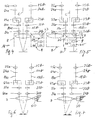
- the two objectives 8 and 9 form a whole with the slide 11, which belongs to the displacement device 10, the aforementioned components of the microscope in FIGS. 4 and 5 are surrounded by a frame with a dashed line.
- the two lenses 8 and 9 are separated from one another by means of a dash-dotted line.
- the objectives 8 and 9 in these figures are arranged as if they were displaceable in the plane of the beam paths 18a and 18b.
- the schematic representation from FIG. 4 corresponds to the representation content from FIG. 1, while FIG. 5 schematically reproduces the position of the slide 11 of the displacement device 10 shown in FIGS. 2 and 3.
- Such a microscope makes it possible to move from switch from normal stereoscopic observation to binocular observation at much higher magnification. Compared to the well-known classic microscope, the image is upright and right-sided. The overview observation can thus be carried out stereoscopically and with a larger field of view and the transition to closer observation of the same point on the object can be accomplished simply by moving the lenses.
- a suitable choice of the inclination of the guide opening 12 in the drive box 3 it can be achieved, for example, that the sharpness of the image remains constant regardless of which of the objectives is in the optical lens C of the microscope.
- This instrument is therefore ideal as a school and hobby microscope, but also for quality control in industry. With stereoscopic overview observation, a test object can be quickly screened. Possible defects can be assessed immediately at high magnification.
- the above-described displaceability of the objectives 8 and 9 of the microscope opens up the possibility of measuring distances on the observed object.
- a corresponding exemplary embodiment of the present microscope is shown schematically in FIGS. 6 and 7.
- the first objective 8, which is used for stereoscopic observation of the object is coupled to a length measuring device 50.
- a scale with vernier reading, a micrometer screw, a mechanical dial gauge, an electronic sensor with digital display, etc. can be used.
- a micrometer screw 50 is used for length measurement.
- the use of a micrometer screw offers an additional advantage, namely that it can also be used to drive the lens shift.
- a crosshair eyepiece should also be used. With the crosshair eyepiece, two points of the object are successively displayed aims, the lens shift between the two targets corresponds exactly to the distance between the two points. It goes without saying that such measurements can also be carried out when the changer 10 does not have a second objective.
- two length measuring devices 50 which are coupled to the main objective 8 are arranged at right angles to one another and if the displacement device 10 permits movements in a horizontal plane, then objects in two coordinate directions, for example in the X and Y directions, can be measured simultaneously.
- a cross table of a known type can be used as such a displacement device.
- the distance to be measured can also be larger than the visual field. Compared to measuring microscopes with object or tube displacement, the mass to be moved is lower in the present microscope.
Landscapes
- Physics & Mathematics (AREA)
- Chemical & Material Sciences (AREA)
- Analytical Chemistry (AREA)
- General Physics & Mathematics (AREA)
- Optics & Photonics (AREA)
- Microscoopes, Condenser (AREA)
- Medicines Containing Antibodies Or Antigens For Use As Internal Diagnostic Agents (AREA)
- Lens Barrels (AREA)
Priority Applications (1)
| Application Number | Priority Date | Filing Date | Title |
|---|---|---|---|
| AT85107880T ATE32792T1 (de) | 1984-06-29 | 1985-06-25 | Mikroskop mit einem binokularen tubus. |
Applications Claiming Priority (2)
| Application Number | Priority Date | Filing Date | Title |
|---|---|---|---|
| CH3157/84 | 1984-06-29 | ||
| CH315784 | 1984-06-29 |
Publications (2)
| Publication Number | Publication Date |
|---|---|
| EP0170857A1 true EP0170857A1 (fr) | 1986-02-12 |
| EP0170857B1 EP0170857B1 (fr) | 1988-03-02 |
Family
ID=4249845
Family Applications (2)
| Application Number | Title | Priority Date | Filing Date |
|---|---|---|---|
| EP85107880A Expired EP0170857B1 (fr) | 1984-06-29 | 1985-06-25 | Microscope comportant un tube binoculaire |
| EP85107879A Expired EP0167926B1 (fr) | 1984-06-29 | 1985-06-25 | Microscope comportant un tube binoculaire |
Family Applications After (1)
| Application Number | Title | Priority Date | Filing Date |
|---|---|---|---|
| EP85107879A Expired EP0167926B1 (fr) | 1984-06-29 | 1985-06-25 | Microscope comportant un tube binoculaire |
Country Status (5)
| Country | Link |
|---|---|
| US (2) | US4697893A (fr) |
| EP (2) | EP0170857B1 (fr) |
| JP (2) | JPS6163816A (fr) |
| AT (2) | ATE32792T1 (fr) |
| DE (2) | DE3565322D1 (fr) |
Cited By (2)
| Publication number | Priority date | Publication date | Assignee | Title |
|---|---|---|---|---|
| EP0236921A3 (en) * | 1986-03-14 | 1990-06-13 | Oculus Optikgerate Gmbh | Supplementary device for microscopes |
| WO2004040352A3 (fr) * | 2002-10-31 | 2004-09-30 | Leica Microsystems Schweiz Ag | Stereomicroscope, ou element rapporte pour stereomicroscope |
Families Citing this family (21)
| Publication number | Priority date | Publication date | Assignee | Title |
|---|---|---|---|---|
| US4872052A (en) * | 1986-12-03 | 1989-10-03 | View Engineering, Inc. | Semiconductor device inspection system |
| US4916532A (en) * | 1987-09-15 | 1990-04-10 | Jerry R. Iggulden | Television local wireless transmission and control |
| US5023931A (en) * | 1987-09-15 | 1991-06-11 | Jerry Iggulden | Television local wireless transmission and control |
| JPS6488420A (en) * | 1987-09-29 | 1989-04-03 | Sumikin Jisho Kk | Stereoscopic image optical device |
| JP2744615B2 (ja) * | 1987-09-30 | 1998-04-28 | 株式会社トプコン | 双眼顕微鏡 |
| JPH01154016A (ja) * | 1987-12-10 | 1989-06-16 | Nikon Corp | 顕微鏡 |
| US5253106A (en) * | 1992-03-20 | 1993-10-12 | Amarel Precision Instruments, Inc. | Oblique viewing system for microscopes |
| US5394267A (en) * | 1993-06-29 | 1995-02-28 | Olympus Optical Co., Ltd. | Stereomicroscope |
| DE19527722A1 (de) * | 1995-07-31 | 1997-02-06 | Leica Mikroskopie & Syst | Objekthalter für dünne Objektträger |
| JPH10161018A (ja) * | 1996-11-27 | 1998-06-19 | Olympus Optical Co Ltd | 光学系 |
| US6128144A (en) | 1996-12-02 | 2000-10-03 | Olympus Optical Co., Ltd. | Optical system for camera and camera apparatus |
| US6226118B1 (en) | 1997-06-18 | 2001-05-01 | Olympus Optical Co., Ltd. | Optical microscope |
| DE59802165D1 (de) * | 1997-09-05 | 2001-12-20 | Leica Microsystems | Mikroskop, insbesondere fluoreszenzmikroskop, insbesondere stereo-fluoreszenzmikroskop |
| US7061672B2 (en) | 2000-06-20 | 2006-06-13 | Kramer Scientific Corporation | Fluorescence microscope |
| US6366044B2 (en) * | 2000-07-04 | 2002-04-02 | Asmo Co., Ltd. | Rotational-position sensing device and windshield wiper system having the same |
| JP2002148523A (ja) * | 2000-11-07 | 2002-05-22 | Nikon Corp | 双眼顕微鏡及び該顕微鏡用光路分割装置 |
| US6930828B2 (en) * | 2002-06-21 | 2005-08-16 | Kramer Scientific Corporation | In vitro fertilization microscope |
| US7315414B2 (en) * | 2004-03-31 | 2008-01-01 | Swift Instruments, Inc. | Microscope with adjustable stage |
| DE102005040473B4 (de) * | 2005-08-26 | 2007-05-24 | Leica Microsystems (Schweiz) Ag | Stereomikroskop |
| DE102006036300B4 (de) * | 2005-08-26 | 2007-11-29 | Leica Microsystems (Schweiz) Ag | Hochleistungs-Stereomikroskop |
| DE102006036768B4 (de) * | 2005-08-26 | 2007-11-29 | Leica Microsystems (Schweiz) Ag | Stereomikroskop nach Greenough |
Citations (4)
| Publication number | Priority date | Publication date | Assignee | Title |
|---|---|---|---|---|
| US1818974A (en) * | 1930-02-19 | 1931-08-18 | Ernst Leitz Optische Werke | Binocular microscope |
| FR1107626A (fr) * | 1954-06-21 | 1956-01-04 | Anciens Ets Barbier | Dispositif de changement de grossissement à parcours brisé |
| US3173984A (en) * | 1959-03-31 | 1965-03-16 | Svenska Ackumulator Ab | Stereomicroscope with interchangeable auxiliary oi'tical units |
| DE3318011A1 (de) * | 1983-05-18 | 1984-11-22 | Fa. Carl Zeiss, 7920 Heidenheim | Zusatzeinrichtung fuer stereomikroskope |
Family Cites Families (12)
| Publication number | Priority date | Publication date | Assignee | Title |
|---|---|---|---|---|
| US1853674A (en) * | 1930-06-04 | 1932-04-12 | Firm Ernst Leitz Optische Werk | Microscope with inclined oculars |
| US2133509A (en) * | 1936-07-08 | 1938-10-18 | Bausch & Lomb | Microscope |
| GB616854A (en) * | 1946-09-13 | 1949-01-27 | John Kemp Enock | Improvements in or relating to simple and compound microscopes |
| DE1278755B (de) * | 1967-01-26 | 1968-09-26 | Leitz Ernst Gmbh | Stereomikroskop |
| CH565379A5 (fr) * | 1974-07-04 | 1975-08-15 | Wild Heerbrugg Ag | |
| JPS60641B2 (ja) * | 1977-07-25 | 1985-01-09 | 株式会社ニコン | 斜視実体顕微鏡 |
| CH651139A5 (de) * | 1980-12-18 | 1985-08-30 | Wild Heerbrugg Ag | Strahlenumlenkvorrichtung fuer ein optisches instrument, insbesondere ein mikroskop. |
| DE3105018A1 (de) * | 1981-02-12 | 1982-09-02 | Fa. Carl Zeiss, 7920 Heidenheim | Operationsmikroskop |
| EP0072652B1 (fr) * | 1981-08-17 | 1985-09-25 | National Research Development Corporation | Microscope stéréoscopique variable |
| DE3217776C2 (de) * | 1982-05-12 | 1985-01-31 | Fa. Carl Zeiss, 7920 Heidenheim | Stereomikroskop |
| DE3229516A1 (de) * | 1982-08-07 | 1984-02-09 | Royonic Elektronik Produktionsmaschinen GmbH, 8057 Eching | Stereomikroskop |
| JPS5999412A (ja) * | 1982-11-29 | 1984-06-08 | Olympus Optical Co Ltd | 単対物立体視顕微鏡 |
-
1985
- 1985-06-25 DE DE8585107879T patent/DE3565322D1/de not_active Expired
- 1985-06-25 DE DE8585107880T patent/DE3561769D1/de not_active Expired
- 1985-06-25 EP EP85107880A patent/EP0170857B1/fr not_active Expired
- 1985-06-25 AT AT85107880T patent/ATE32792T1/de active
- 1985-06-25 EP EP85107879A patent/EP0167926B1/fr not_active Expired
- 1985-06-25 AT AT85107879T patent/ATE37616T1/de not_active IP Right Cessation
- 1985-06-27 US US06/749,273 patent/US4697893A/en not_active Expired - Fee Related
- 1985-06-27 US US06/749,275 patent/US4717246A/en not_active Expired - Lifetime
- 1985-06-28 JP JP60141430A patent/JPS6163816A/ja active Pending
- 1985-06-28 JP JP60141431A patent/JPS61112116A/ja active Pending
Patent Citations (4)
| Publication number | Priority date | Publication date | Assignee | Title |
|---|---|---|---|---|
| US1818974A (en) * | 1930-02-19 | 1931-08-18 | Ernst Leitz Optische Werke | Binocular microscope |
| FR1107626A (fr) * | 1954-06-21 | 1956-01-04 | Anciens Ets Barbier | Dispositif de changement de grossissement à parcours brisé |
| US3173984A (en) * | 1959-03-31 | 1965-03-16 | Svenska Ackumulator Ab | Stereomicroscope with interchangeable auxiliary oi'tical units |
| DE3318011A1 (de) * | 1983-05-18 | 1984-11-22 | Fa. Carl Zeiss, 7920 Heidenheim | Zusatzeinrichtung fuer stereomikroskope |
Cited By (3)
| Publication number | Priority date | Publication date | Assignee | Title |
|---|---|---|---|---|
| EP0236921A3 (en) * | 1986-03-14 | 1990-06-13 | Oculus Optikgerate Gmbh | Supplementary device for microscopes |
| WO2004040352A3 (fr) * | 2002-10-31 | 2004-09-30 | Leica Microsystems Schweiz Ag | Stereomicroscope, ou element rapporte pour stereomicroscope |
| US7538939B2 (en) | 2002-10-31 | 2009-05-26 | Leica Microsystems (Schweiz) Ag | Stereomicroscope or additional element for a stereomicroscope |
Also Published As
| Publication number | Publication date |
|---|---|
| US4697893A (en) | 1987-10-06 |
| DE3561769D1 (en) | 1988-04-07 |
| ATE37616T1 (de) | 1988-10-15 |
| DE3565322D1 (en) | 1988-11-03 |
| EP0167926A1 (fr) | 1986-01-15 |
| ATE32792T1 (de) | 1988-03-15 |
| US4717246A (en) | 1988-01-05 |
| JPS61112116A (ja) | 1986-05-30 |
| EP0170857B1 (fr) | 1988-03-02 |
| JPS6163816A (ja) | 1986-04-02 |
| EP0167926B1 (fr) | 1988-09-28 |
Similar Documents
| Publication | Publication Date | Title |
|---|---|---|
| EP0170857B1 (fr) | Microscope comportant un tube binoculaire | |
| EP1276586B1 (fr) | Dispositif de microdissection laser | |
| DE4323329C2 (de) | Mikroskopsystem | |
| EP2181352B1 (fr) | Microscope à focalisation interne | |
| DE102012020877A1 (de) | Optikanordnung und Lichtmikroskop | |
| DE4131737A1 (de) | Autofokus-anordnung fuer ein stereomikroskop | |
| DE3602095A1 (de) | Stereomikroskop | |
| DE19803106A1 (de) | Konfokales Mikrospektrometer-System | |
| EP0908709B1 (fr) | Dispositif de mesure sans contact de vibrations | |
| DE102007029893A1 (de) | Mikroskop mit zentrierter Beleuchtung | |
| DE3318011C2 (de) | Zusatzeinrichtung für Stereomikroskope | |
| DE19604363A1 (de) | Zusatzmodul zur ortsaufgelösten Fokusvermessung | |
| DE3888911T2 (de) | Binokulares Mikroskop. | |
| EP0055209A2 (fr) | Dispositif pour faire tourner des faisceaux lumineux | |
| DE102008011527B4 (de) | Beleuchtungseinrichtung für ein Mikroskop | |
| DE4113279A1 (de) | Verfahren und vorrichtung zum abbilden eines objektes | |
| DE102014118025B4 (de) | Vorrichtung zur Lichtblattmikroskopie | |
| EP1064581B1 (fr) | Microscopie video | |
| CH469480A (de) | Spaltlampengerät für Augenuntersuchungen | |
| EP1985227A1 (fr) | Composant optique pour un microscope stéreoscopique | |
| DE3116074C2 (de) | Funduskamera zur Augenuntersuchung | |
| DE10135321B4 (de) | Mikroskop und Verfahren zur Untersuchung einer Probe mit einem Mikroskop | |
| DE2718711A1 (de) | Vorrichtung zur abtastung eines objektes mit einem lichtstrahl | |
| DE19829982A1 (de) | Verfahren zur Ansteuerung eines Laser-Scanning-Mikroskopes mit einem kippbaren Feinfokussiertisch | |
| DE3744156A1 (de) | Inversmikroskop fuer durchlichtbeleuchtung |
Legal Events
| Date | Code | Title | Description |
|---|---|---|---|
| PUAI | Public reference made under article 153(3) epc to a published international application that has entered the european phase |
Free format text: ORIGINAL CODE: 0009012 |
|
| AK | Designated contracting states |
Designated state(s): AT CH DE FR GB IT LI |
|
| 17P | Request for examination filed |
Effective date: 19860416 |
|
| 17Q | First examination report despatched |
Effective date: 19870305 |
|
| ITF | It: translation for a ep patent filed | ||
| GRAA | (expected) grant |
Free format text: ORIGINAL CODE: 0009210 |
|
| AK | Designated contracting states |
Kind code of ref document: B1 Designated state(s): AT CH DE FR GB IT LI |
|
| REF | Corresponds to: |
Ref document number: 32792 Country of ref document: AT Date of ref document: 19880315 Kind code of ref document: T |
|
| GBT | Gb: translation of ep patent filed (gb section 77(6)(a)/1977) | ||
| REF | Corresponds to: |
Ref document number: 3561769 Country of ref document: DE Date of ref document: 19880407 |
|
| ET | Fr: translation filed | ||
| PLBE | No opposition filed within time limit |
Free format text: ORIGINAL CODE: 0009261 |
|
| STAA | Information on the status of an ep patent application or granted ep patent |
Free format text: STATUS: NO OPPOSITION FILED WITHIN TIME LIMIT |
|
| 26N | No opposition filed | ||
| PGFP | Annual fee paid to national office [announced via postgrant information from national office to epo] |
Ref country code: AT Payment date: 19920529 Year of fee payment: 8 |
|
| PG25 | Lapsed in a contracting state [announced via postgrant information from national office to epo] |
Ref country code: AT Effective date: 19930625 |
|
| ITTA | It: last paid annual fee | ||
| PGFP | Annual fee paid to national office [announced via postgrant information from national office to epo] |
Ref country code: DE Payment date: 19940514 Year of fee payment: 10 |
|
| PGFP | Annual fee paid to national office [announced via postgrant information from national office to epo] |
Ref country code: GB Payment date: 19940516 Year of fee payment: 10 Ref country code: CH Payment date: 19940516 Year of fee payment: 10 |
|
| PGFP | Annual fee paid to national office [announced via postgrant information from national office to epo] |
Ref country code: FR Payment date: 19940519 Year of fee payment: 10 |
|
| PG25 | Lapsed in a contracting state [announced via postgrant information from national office to epo] |
Ref country code: GB Effective date: 19950625 |
|
| PG25 | Lapsed in a contracting state [announced via postgrant information from national office to epo] |
Ref country code: LI Effective date: 19950630 Ref country code: CH Effective date: 19950630 |
|
| GBPC | Gb: european patent ceased through non-payment of renewal fee |
Effective date: 19950625 |
|
| PG25 | Lapsed in a contracting state [announced via postgrant information from national office to epo] |
Ref country code: FR Effective date: 19960229 |
|
| REG | Reference to a national code |
Ref country code: CH Ref legal event code: PL |
|
| PG25 | Lapsed in a contracting state [announced via postgrant information from national office to epo] |
Ref country code: DE Effective date: 19960301 |
|
| REG | Reference to a national code |
Ref country code: FR Ref legal event code: ST |