EP0170911A2 - Machine pour l'épandage de matériaux, en particulier d'engrais - Google Patents
Machine pour l'épandage de matériaux, en particulier d'engrais Download PDFInfo
- Publication number
- EP0170911A2 EP0170911A2 EP85108510A EP85108510A EP0170911A2 EP 0170911 A2 EP0170911 A2 EP 0170911A2 EP 85108510 A EP85108510 A EP 85108510A EP 85108510 A EP85108510 A EP 85108510A EP 0170911 A2 EP0170911 A2 EP 0170911A2
- Authority
- EP
- European Patent Office
- Prior art keywords
- lines
- vehicle
- storage container
- spreading
- injectors
- Prior art date
- Legal status (The legal status is an assumption and is not a legal conclusion. Google has not performed a legal analysis and makes no representation as to the accuracy of the status listed.)
- Granted
Links
Images


Classifications
-
- A—HUMAN NECESSITIES
- A01—AGRICULTURE; FORESTRY; ANIMAL HUSBANDRY; HUNTING; TRAPPING; FISHING
- A01C—PLANTING; SOWING; FERTILISING
- A01C15/00—Fertiliser distributors
- A01C15/04—Fertiliser distributors using blowers
Definitions
- the invention relates to a device for spreading pourable material, in particular fertilizer or the like, with a storage container mounted on the platform of a vehicle, for example a system tractor, a self-propelled vehicle or a trailer, and a pneumatic spreading device which is picked up by a lifting linkage, for example a three-point linkage , which has several, extending on both sides of the vehicle's longitudinal axis and transversely to it, outside at different distances from it at manifolds and foldable into a driving position: stray lines that have one inside each Injector and an air distributor are connected to at least one blower driven by the vehicle, for example a PTO shaft, and to which the spreading material is fed by means of metering elements in the area of the injectors.
- a lifting linkage for example a three-point linkage
- the spreading unit is a structural unit consisting of the storage container, the metering elements arranged below its outlet openings, the blower with the air distributors and the adjoining injectors which are arranged below the metering elements, as well as the scatter lines.
- This unit is taken up by the three-point linkage of a tractor.
- the blower is driven by the tractor's PTO shaft, from which the metering elements can also be driven. If necessary, these can also have their own hydraulic drive, which is connected to the hydraulic network of the tractor.
- the spreading width is limited by the following factors: The larger the spreading width, the greater the capacity of the storage container must be in order to get a filling with the tramline process until the end of the field.
- one filling should even suffice for a return trip, since the storage container can generally only be refilled on one side of the field.
- the payload is limited in several ways. Since the entire spreading unit with storage container and payload is behind the rear axle of the tractor, the ground pressure of the rear axle is correspondingly high. This ground pressure is said to be ge ring as possible. If a certain weight is exceeded, the ability of the tractor to steer is considerably impaired, which can lead to displacement or even overturning on sloping terrain.
- the spreading width is set even lower.
- the spreading unit can often only be raised to such an extent that it lies directly above the planting. Due to the high center of gravity, minor unevenness in the soil is reflected in fluctuations in the scatter lines, which, when long, have a considerable amplitude and can lead to damage to the ground.
- spreading units are also used in trailer operation (FR-OS 23 82 171), which can improve the center of gravity, but this advantage is bought with other serious disadvantages.
- the poorer maneuverability of the entire train must be mentioned here first.
- the soil stress is increased by the wheels of at least one further axle and, due to the greater distance between the tractor and the spreading unit, complex drive connections are required.
- Another disadvantage is the fact that late fertilization is not possible because the spreading unit cannot be raised. This is unsustainable in modern agricultural operations, in which the fertilizer required for a growing period is spread in several doses to suit the needs and the weather.
- the stray lines from the semi-mounted front are still known for trailer operation, but also for direct mounting Guide the container first to the rear and then to the side via 90 ° deflections.
- the dosing elements are arranged transversely to the direction of travel below the container and are therefore not accessible for trial dosing, cleaning work etc., at least in the saddled state. Due to the necessary deflection of the flow in the area of the highest conveying speed, on the one hand a high blower output is necessary, on the other hand there is a lot of wear in the pipe bends and corresponding abrasion on the product. Also, especially with moist fertilizer, caking and eventually blockages occur.
- system tractors or self-propelled vehicles are often used instead of or in addition to add-on tractors, which offer a wide range of attachment options and can be used to carry out work that cannot be done with the tractor.
- the advantage of this combination is that the entire payload does not have to be absorbed by the three-point linkage, so that the center of gravity in the area of Rear axle is.
- the fertilizer has to be transferred from the saddled container into the smaller storage container of the spreading unit.
- the invention has for its object to provide a device of the above-mentioned and most recently recognized structure so that at maximum spreading width and the greatest possible payload a lower unladen weight and a favorable load distribution with the lowest soil load is obtained and during the spreading operation transfer work or the like is omitted.
- this object is achieved in that the metering elements are arranged below the outlet openings provided on the saddled storage container and in that a number of transport lines corresponding to the number of scatter lines is provided, each of which, on the one hand, via. an injector below the metering elements for receiving the spreading material and via an air distributor to a blower, and on the other hand to an injector of a scatter line.
- the solution according to the invention is based on the principle of shifting the metering process to the storage container and pneumatically feeding the metered spreading material from the storage container to the injectors of the scattering lines by means of the transport lines.
- the entire contents of the saddled storage container which is favorably placed on or even in front of the rear axle, is continuously fed to the spreading unit in metered form.
- the content of the container generally extends over several beats, so that the intervals for refilling are determined solely by the maximum payload of the saddled storage container. No transfer operations are necessary during spreading.
- the invention can be dispensed with a further storage container in the spreader unit, so that on the three-point linkage of the vehicle, e.g.
- the payload can be increased to a value that is limited only by the permissible soil stress or the tractor load-bearing capacity. This and the large refilling intervals open up the possibility, compared to the known devices, of providing even larger spreading widths, for example over 18 m.
- the lower weight on the three-point linkage also reduces the problems with late fertilization described above, since the center of gravity conditions only deteriorate insignificantly even when the spreading unit is raised.
- the pendulum movements triggered by uneven floors can be completely avoid according to the invention by a pendulum suspension of the spreading unit.
- the stray lines and the transport lines are each assigned their own blowers. This measure is recommended because the transport lines only have to overcome a short conveying distance between the saddled storage container and the spreading unit hanging on the three-point linkage, so that only a very low blower output is required, since the spreading material no longer has any kinetic energy when it is fed into the spreading lines must have, while for the transport of the spreading material in the spreading lines, especially in the case of large spreading widths, a greater blower capacity is necessary in order to provide the kinetic energy necessary for the distribution at the outlet.
- the blower assigned to the transport lines can also be controlled separately, for example by means of a throttle valve arranged on the suction side, in order to adapt the power to the metering capacity of the metering elements or to adjust it so that the spreading material is still transported safely, as a result of which wear on the Transport lines and product abrasion can be kept to a minimum.
- the height adjustment of the spreading unit also has no disadvantages, since there are low air speeds in the transport lines that must follow the height movement.
- both fans have a common drive shaft, so that the overall size is kept to a minimum and both fans can be connected, for example, to the PTO by a coupling process.
- the blowers can either be arranged on the loading platform or on a frame of the spreading unit. The order on the spreading unit has the advantage that it enables the relatively simple PTO connection.
- the second blower is connected on the pressure side to the air distributors for the transport lines via at least one air line guided below the storage container.
- This can be a simple hose line.
- the frame of the spreading unit forms the part of a lifting frame that can be raised and lowered, the other part of which is connected to the three-point linkage.
- This embodiment is particularly intended for late fertilization if the lifting range of the three-point linkage is not sufficient for late fertilization.
- the spreading unit can be raised up to 2 m, so that the same distance to the grown fruit as with soil fertilization can be maintained.
- the fan drive shaft to the PTO. It is therefore provided, if at least one of the two fans is arranged on the frame forming the liftable and lowerable part of the lifting frame, that the drive shaft of this fan with the PTO shaft via a variable-length gear part, e.g. a belt drive that can be shortened by means of lateral spring pressure is connected.
- a variable-length gear part e.g. a belt drive that can be shortened by means of lateral spring pressure
- the blower or both blowers are connected to the frame part arranged on the three-point linkage and connected to the air distributors or injectors via flexible air lines.
- the frame of the spreader unit is that of the three-point linkage
- Liftable part of the mast is connected to the three-point linkage via a self-aligning bearing arranged approximately in the longitudinal axis of the vehicle, in order to enable pendulum compensation even in any height position.
- the stray lines on each side of the vehicle possibly together with other components assigned to them, e.g. the injectors, about an axis running parallel to the longitudinal axis of the vehicle, in order to enable a parallel arrangement of the stray lines parallel to the ground, independently of one another, because of the pendulum compensation, even on hilly terrain.
- the storage container together with metering elements and the injectors, form a structural unit
- the dosing elements and outlet openings are easily accessible by dismantling the transport lines, so that trial dosing or cleaning work on the dosing elements and outlet openings can be carried out without hindrance. It is also possible to empty the storage container only under the action of gravity - possibly with the dosing elements running along - without the spreading material having to be discharged over the entire pneumatic system.
- the air line between the blower and the air distributors below the storage container is also with the blower easily detachably connected in order to facilitate the mounting and dismounting of the spreading unit and the production or solution of the pneumatic connection between the spreading unit and the storage container.
- the storage container preferably has an outlet opening running parallel to the longitudinal axis of the vehicle on each side, below which a group of metering elements is arranged, which are assigned to the stray lines on each side of the vehicle via the transport lines.
- outlet openings and the metering elements are expediently shifted into the area of the outer side boundaries of the storage container in order to obtain the greatest possible payload on the one hand, and on the other hand good accessibility of the outlet openings or metering elements when the storage container is saddled after the transport lines have been dismantled. It is also possible in this way to guide the air line from the blower approximately in the longitudinal axis of the vehicle below the storage container and to divide the air into air distributors arranged on both sides of the longitudinal axis of the vehicle.
- the storage container may have a single outlet opening running transversely to the longitudinal axis of the vehicle, below which all metering elements are arranged one behind the other and transversely to the longitudinal axis of the vehicle, the metering elements arranged towards one side of the vehicle being assigned to the scatter lines arranged on the same side of the vehicle .
- the metering elements are advantageously located in the area of the rear wall of the storage container, where they are easily accessible.
- the spreading material is also conveyed in the area of the transport lines with the least possible deflection, since it is first transported in a straight line from the metering elements and only has to be deflected to the extent required by the level difference between the injectors on the storage container and the injectors on the scatter lines .
- curved sections cannot be avoided in the area of the transport lines, they preferably consist of flexible hoses which, on the one hand, facilitate the routing of the lines and, above all, the replacement of damaged lines. Furthermore, such flexible lines are less sensitive to wear from the spreading material conveyed in them than metallic lines and are also less expensive, so that the need for replacement is correspondingly favorable.
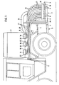
- a large-volume storage container 2 On the platform 1 of the system tractor, a large-volume storage container 2 is saddled, which holds the grit.
- the system tractor also has a three-point linkage 3 consisting of two lower links 4 and an upper link 5, to which the frame 6 of a spreading unit 7 is attached.
- the spreading unit 7 consists in a conventional manner of a plurality of scatter lines 8 arranged in parallel next to one another, which extend in bundles from the longitudinal axis of the vehicle and open out at distribution points 9 at different distances.
- These distribution elements consist, for example, of baffle plates, which are arranged in front of the openings of the scatter lines bent backwards.
- the spreading unit also has a blower 11, the axis 12 of which is coupled, for example, to the PTO of the system tractor.
- the blower 11 has two pressure outlets 13, which lead to air distributors 14 which extend over the entire width of the scatter lines 8 and distribute the air to the individual scatter lines.
- the scatter lines 8 each have an injector 15 (FIG. 3), above which a box 16, which is guided over all lines, is arranged for the purpose of the spreading material.
- the stray lines 8 are connected to the injectors via rubber sleeves 17 or the like, so that they can be folded upward about an axis (not shown).
- the scatter lines 8 have a plurality of mutually articulated sections (not shown) around which they are folded, so that, despite their great length, they can be folded together at a relatively low height and folded up into the driving position.
- the saddle tank 2 saddled on the system tractor has outlet openings 17 arranged on both sides of the longitudinal axis of the vehicle, in each case close to the side boundary of the storage tank, in the area of which metering elements are mounted in the form of axially parallel cam wheels.
- metering bowls 19 are arranged under resilient contact with the metering elements, via which the metered spreading material arrives in collecting bowls 20.
- Each drip tray 20 belongs to a transport line 21, the number of transport lines corresponding to the number of stray lines 8.
- the transport lines 21 of each container side are assigned to the scatter lines 8 of the scattering unit 7 on the corresponding vehicle side.
- three dosing lines are assigned to each metering element, which accordingly lead to three stray lines.
- the transport lines point in the area the drip trays 20 each have an injector 22, all injectors being preceded by an air distributor 23 which is connected via an air line 24 to a further blower 25 (see FIG. 2).
- the transport lines 21 - in the exemplary embodiment shown in each case into three - are combined and, as shown in FIG. 1, are routed one behind the other to the scattering unit 7. There they have a downwardly curved section 26 bridging the level difference and adjoining vertical sections 27 which then open into the feed box 16 above the injectors 15 at the scatter lines 8.
- the blower 11 for the stray lines 8 and the blower 25 for the transport lines 21 can sit on a common axis 12 so that they can be connected to the PTO shaft by only one coupling operation.
- the transport blower 25 can have a lower output than the delivery blower 11 and can also be equipped on the suction side with a throttle valve in order to control the air output.
- the frame 6 of the spreading unit 7 is connected to a crossbar of the three-point linkage 3 via a self-aligning bearing 28 arranged in the longitudinal axis of the vehicle, so that the entire spreading unit 7 can swing about the bearing 28.
- a further frame component can be used between the three-point linkage 3 and the self-aligning bearing 28, which together with the frame 6 forms a type of lifting frame, so that the Frame 6 is vertically displaceable on this component.
- the stray lines 8 on each side of the vehicle can be pivoted axially parallel with respect to the frame 6, in order to have a different inclination in sloping terrain to allow the stray lines on both sides of the vehicle.
- the metering elements 19 can also be arranged transversely to the longitudinal axis of the vehicle, for example in the transverse central axis or in the area the rear wall of the storage container 2 can be arranged one behind the other, in which case the transport lines 21 do not protrude beyond the lateral limitation of the storage container, but are led out to the rear.
- the storage container 2 can be enlarged to the side without exceeding the permissible width, and the spreading material in the transport lines 21 is deflected only once over the curved sections 26.
- the transport lines 21 are preferably made of a flexible material, e.g. Rubber materials, plastic or the like.
- the metering elements 18 are preferably driven hydraulically and supplied by the hydraulic network of the system tractor, which enables easy speed control and thus very precise metering, which is primarily independent of the other vehicle drive.
- the transport lines 21 can - if appropriate together with the injectors 22 with collecting trays 20 - be combined to form a structural unit. They are also easily detachably attached to the feed box 16, so that this unit can be solved without difficulty. Likewise, the air line 24 (or the air lines) is detachably attached to the blower 25 and / or to the air distributors 23, so that the entire spreading unit can be separated from the storage container 2 or the transport lines 21 without difficulty and can also be connected to it without problems.
- a lifting frame can be used between the three-point linkage 3 and the spreading unit 7, the leading part of which sits on the three-point linkage 3.
- the guided part which carries out the lifting and lowering movement, receives the self-aligning bearing 28 with the spreading unit 7.
- the blowers 11, 25, however, preferably sit on the leading part, so that they can be coupled directly to the PTO.
- the stroke between the spreading unit 7 on the one hand and the storage container 2 on the other hand can be easily accommodated in the flexible air lines 13 or 24 (FIG. 3) by means of appropriate loops or curvatures.
- the storage container 2 and the control unit 7 can also be used in the same way in connection with a self-propelled vehicle or a trailer, provided that the trailer has corresponding coupling options with lifting devices. When saddling onto a trailer, it can be fitted with care tires (large diameter, narrow width).
Landscapes
- Life Sciences & Earth Sciences (AREA)
- Soil Sciences (AREA)
- Environmental Sciences (AREA)
- Fertilizing (AREA)
- Vending Machines For Individual Products (AREA)
- Warehouses Or Storage Devices (AREA)
- Fertilizers (AREA)
- Sowing (AREA)
Priority Applications (1)
| Application Number | Priority Date | Filing Date | Title |
|---|---|---|---|
| AT85108510T ATE46421T1 (de) | 1984-08-07 | 1985-07-09 | Vorrichtung zum streuen von schuettfaehigem gut, insbesondere duenger. |
Applications Claiming Priority (2)
| Application Number | Priority Date | Filing Date | Title |
|---|---|---|---|
| DE3429042A DE3429042C1 (de) | 1984-08-07 | 1984-08-07 | Vorrichtung zum Streuen von schuettfaehigem Gut,insbesondere Duenger |
| DE3429042 | 1984-08-07 |
Publications (3)
| Publication Number | Publication Date |
|---|---|
| EP0170911A2 true EP0170911A2 (fr) | 1986-02-12 |
| EP0170911A3 EP0170911A3 (en) | 1986-12-17 |
| EP0170911B1 EP0170911B1 (fr) | 1989-09-20 |
Family
ID=6242510
Family Applications (1)
| Application Number | Title | Priority Date | Filing Date |
|---|---|---|---|
| EP85108510A Expired EP0170911B1 (fr) | 1984-08-07 | 1985-07-09 | Machine pour l'épandage de matériaux, en particulier d'engrais |
Country Status (4)
| Country | Link |
|---|---|
| EP (1) | EP0170911B1 (fr) |
| AT (1) | ATE46421T1 (fr) |
| DE (1) | DE3429042C1 (fr) |
| DK (1) | DK160598C (fr) |
Cited By (1)
| Publication number | Priority date | Publication date | Assignee | Title |
|---|---|---|---|---|
| WO2019140526A1 (fr) * | 2018-01-22 | 2019-07-25 | Salford Group Inc | Épandeur à rampe pneumatique pour produit agricole |
Families Citing this family (9)
| Publication number | Priority date | Publication date | Assignee | Title |
|---|---|---|---|---|
| DE3664090D1 (en) | 1985-04-27 | 1989-08-03 | Rauch Landmaschfab Gmbh | Device for distributing of fertilizer or the like |
| DE3539754C1 (de) * | 1985-11-09 | 1989-10-12 | Rauch Landmaschinenfabrik GmbH, 7573 Sinzheim | Vorrichtung zum Streuen von Dünger oder dergleichen |
| DE3540226A1 (de) * | 1985-11-13 | 1987-05-14 | Amazonen Werke Dreyer H | Verteilmaschine, insbesondere pneumatikduengerstreuer |
| DE10331913B4 (de) * | 2003-07-15 | 2013-09-12 | Rauch Landmaschinenfabrik Gmbh | Vorrichtung zum Verteilen von Streugut, insbesondere Dünger, Saatgut oder dergleichen |
| DE102004030240B4 (de) * | 2003-07-15 | 2015-07-09 | Rauch Landmaschinenfabrik Gmbh | Pneumatischer Streuer zum Verteilen von Streugut, insbesondere Dünger, Saatgut oder dergleichen |
| DE102007038510B4 (de) | 2007-08-14 | 2020-01-16 | Rauch Landmaschinenfabrik Gmbh | Vorrichtung zum Dosieren und Verteilen von landwirtschaftlichen und kommunalen Schüttgütern |
| SE1250199A1 (sv) * | 2012-03-01 | 2013-09-02 | Vaederstad Verken Ab | Lantbruksredskap med minst två matningsanordningar för luftflödesbaserad matning av granulärt eller pulverformigt material |
| US10278326B2 (en) | 2017-06-05 | 2019-05-07 | Cnh Industrial Canada, Ltd. | Fertilizer application system using pneumatic conveying with large diameter lines and rotary distributor |
| CN117958000A (zh) * | 2023-12-26 | 2024-05-03 | 江苏盐城港盐农循环农业有限公司 | 一种多使用模式的沼液肥施肥机 |
Family Cites Families (16)
| Publication number | Priority date | Publication date | Assignee | Title |
|---|---|---|---|---|
| CH70382A (de) * | 1914-12-21 | 1915-09-16 | Simon Eckart | Kunstdüngerstreumaschine |
| US1785945A (en) * | 1929-03-07 | 1930-12-23 | Richard R Ezdorf | Dual fan-dusting machine |
| DE1657591B1 (de) * | 1966-01-22 | 1970-07-16 | Heinrich Weiste | Vorrichtung zum Saeen von Korn und/oder Streuen von koernigem Duenger |
| SE325164B (fr) * | 1968-08-22 | 1970-06-22 | Ystads Gjuteri Mek Verk | |
| DE2300399B2 (de) * | 1973-01-05 | 1977-01-27 | Amazonen-Werke H. Dreyer, 4507 Hasbergen | Fahrzeug mit behaelter zum befuellen von maschinen zur materialausbringung |
| DE2443499A1 (de) * | 1974-09-11 | 1976-03-25 | Amazonen Werke Dreyer H | Maschine zum ausbringen von saatgut und duengemitteln |
| DE2503777A1 (de) * | 1975-01-30 | 1976-08-05 | Josef Gail | Duengerstreuvorrichtung |
| US4060181A (en) * | 1975-07-03 | 1977-11-29 | Nodet-Gougis (Societe De Droit Francais) | Method and apparatus for controlling the transfer of particulate material |
| FR7603519A (fr) * | 1976-02-09 | |||
| DE2656279C2 (de) * | 1976-12-11 | 1978-11-23 | Amazonen-Werke H. Dreyer Gmbh & Co Kg, 4507 Hasbergen | Anbauvorrichtung für das Spritzgestänge einer Feldspritze |
| FR2382171A1 (fr) * | 1977-03-04 | 1978-09-29 | Nodet Gougis | Epandeur pneumatique a rampes d'epandage pivotantes |
| DE2803889C3 (de) * | 1978-01-30 | 1980-10-02 | Amazonen-Werke H. Dreyer Gmbh & Co Kg, 4507 Hasbergen | Maschine zum Ausbringen von körnigem Material |
| DE3214331A1 (de) * | 1981-05-25 | 1982-12-09 | Debreceni Mezögazdasági Gépgyártó és Szolgáltató Vállalat, 4001 Debrecen | Vorrichtung zur einstellung eines spruehrahmens an pflanzenschutzgeraeten |
| DE3227487C2 (de) * | 1981-10-06 | 1984-04-05 | Amazonen-Werke H. Dreyer Gmbh & Co Kg, 4507 Hasbergen | Maschine zum pneumatischen Ausbringen von körnigem Material |
| DE3248751C2 (de) * | 1982-12-31 | 1985-01-31 | Rauch Landmaschinenfabrik GmbH, 7573 Sinzheim | Vorrichtung zum Streuen von schüttfähigem Gut |
| DE3539754C1 (de) * | 1985-11-09 | 1989-10-12 | Rauch Landmaschinenfabrik GmbH, 7573 Sinzheim | Vorrichtung zum Streuen von Dünger oder dergleichen |
-
1984
- 1984-08-07 DE DE3429042A patent/DE3429042C1/de not_active Expired
-
1985
- 1985-07-09 AT AT85108510T patent/ATE46421T1/de not_active IP Right Cessation
- 1985-07-09 EP EP85108510A patent/EP0170911B1/fr not_active Expired
- 1985-08-06 DK DK357085A patent/DK160598C/da not_active IP Right Cessation
Cited By (2)
| Publication number | Priority date | Publication date | Assignee | Title |
|---|---|---|---|---|
| WO2019140526A1 (fr) * | 2018-01-22 | 2019-07-25 | Salford Group Inc | Épandeur à rampe pneumatique pour produit agricole |
| US10918013B2 (en) | 2018-01-22 | 2021-02-16 | Salford Group Inc. | Air boom spreader for agricultural product |
Also Published As
| Publication number | Publication date |
|---|---|
| ATE46421T1 (de) | 1989-10-15 |
| EP0170911B1 (fr) | 1989-09-20 |
| DK357085D0 (da) | 1985-08-06 |
| EP0170911A3 (en) | 1986-12-17 |
| DK160598B (da) | 1991-04-02 |
| DK160598C (da) | 1991-09-02 |
| DE3429042C1 (de) | 1988-10-20 |
| DK357085A (da) | 1986-02-08 |
Similar Documents
| Publication | Publication Date | Title |
|---|---|---|
| DE1902715A1 (de) | Landwirtschaftliche Maschine zum Ausstreuen von koernigem Gut,insbesondere von Saat- und/oder Duengemitteln | |
| DE2534596C2 (fr) | ||
| EP0170911B1 (fr) | Machine pour l'épandage de matériaux, en particulier d'engrais | |
| DE4238019C2 (de) | Landwirtschaftliche Gerätekombination mit einer pneumatischen Sämaschine und einer Bodenbearbeitungsmaschine | |
| EP0679326A1 (fr) | Chariot trainé avec roues porteurs | |
| EP0066238B1 (fr) | Récolteuse pour récolter des denrées arrangées en files | |
| DE2107575A1 (de) | Anordnung der Aufbereitungseinnch tung an einem selbstfahrenden Schwadmäher | |
| DE60315831T2 (de) | Landmaschine | |
| DE3513739A1 (de) | Vorrichtung zum streuen von duenger | |
| DE3539754C1 (de) | Vorrichtung zum Streuen von Dünger oder dergleichen | |
| DE102022103794A1 (de) | Pneumatischer Düngerstreuer | |
| DE3512226A1 (de) | Duengeverteiler | |
| DE1757198C3 (de) | Tragvorrichtung für Kartoffellegeeinheiten | |
| EP0202462B1 (fr) | Dispositif pour distribuer de l'engrais ou un produit similaire | |
| EP2074879B1 (fr) | Engin porteur automoteur | |
| DE3644158A1 (de) | Einachsiges fahrzeug, insbesondere fuer die landwirtschaft, den garten- und landschaftsbau | |
| AT396601B (de) | Vorrichtung zum beladen und heben eines oben offenen vorratsbehälters für sand, salz, düngemittel od.dgl., insbesonders eines dosier- oder streugerätes | |
| DE888025C (de) | Kartoffelpflanzmaschine | |
| DE102016119768A1 (de) | Dolly Fahrwerk mit Gummikettenlaufwerk an einer Sämaschine | |
| DE69000563T2 (de) | Landwirtschaftliche maschine mit egge und saegeraet. | |
| EP1129607B1 (fr) | Machine à planter les pommes de terre | |
| DE10331913B4 (de) | Vorrichtung zum Verteilen von Streugut, insbesondere Dünger, Saatgut oder dergleichen | |
| DE102024112921A1 (de) | Pneumatischer Düngerstreuer und Verfahren zum Ausbringen von körnigem landwirtschaftlichem Streugut | |
| AT211601B (de) | Gebläsegerät zum Verteilen von Pflanzenschutzmitteln | |
| DE102023120172A1 (de) | Düngemittelverteiler zur bodennahen Ausbringung von Düngemitteln |
Legal Events
| Date | Code | Title | Description |
|---|---|---|---|
| PUAI | Public reference made under article 153(3) epc to a published international application that has entered the european phase |
Free format text: ORIGINAL CODE: 0009012 |
|
| AK | Designated contracting states |
Designated state(s): AT BE CH FR GB IT LI NL SE |
|
| PUAL | Search report despatched |
Free format text: ORIGINAL CODE: 0009013 |
|
| AK | Designated contracting states |
Kind code of ref document: A3 Designated state(s): AT BE CH FR GB IT LI NL SE |
|
| 17P | Request for examination filed |
Effective date: 19870227 |
|
| 17Q | First examination report despatched |
Effective date: 19880623 |
|
| GRAA | (expected) grant |
Free format text: ORIGINAL CODE: 0009210 |
|
| AK | Designated contracting states |
Kind code of ref document: B1 Designated state(s): AT BE CH FR GB IT LI NL SE |
|
| PG25 | Lapsed in a contracting state [announced via postgrant information from national office to epo] |
Ref country code: SE Effective date: 19890920 Ref country code: NL Effective date: 19890920 Ref country code: IT Free format text: LAPSE BECAUSE OF FAILURE TO SUBMIT A TRANSLATION OF THE DESCRIPTION OR TO PAY THE FEE WITHIN THE PRESCRIBED TIME-LIMIT;WARNING: LAPSES OF ITALIAN PATENTS WITH EFFECTIVE DATE BEFORE 2007 MAY HAVE OCCURRED AT ANY TIME BEFORE 2007. THE CORRECT EFFECTIVE DATE MAY BE DIFFERENT FROM THE ONE RECORDED. Effective date: 19890920 Ref country code: BE Effective date: 19890920 |
|
| REF | Corresponds to: |
Ref document number: 46421 Country of ref document: AT Date of ref document: 19891015 Kind code of ref document: T |
|
| ET | Fr: translation filed | ||
| GBT | Gb: translation of ep patent filed (gb section 77(6)(a)/1977) | ||
| NLV1 | Nl: lapsed or annulled due to failure to fulfill the requirements of art. 29p and 29m of the patents act | ||
| PLBI | Opposition filed |
Free format text: ORIGINAL CODE: 0009260 |
|
| PG25 | Lapsed in a contracting state [announced via postgrant information from national office to epo] |
Ref country code: AT Effective date: 19900709 |
|
| PG25 | Lapsed in a contracting state [announced via postgrant information from national office to epo] |
Ref country code: LI Effective date: 19900731 Ref country code: CH Effective date: 19900731 |
|
| 26 | Opposition filed |
Opponent name: AMAZONEN-WERK H. DREYER GMBH & CO. KG Effective date: 19900608 |
|
| REG | Reference to a national code |
Ref country code: CH Ref legal event code: PL |
|
| PLBN | Opposition rejected |
Free format text: ORIGINAL CODE: 0009273 |
|
| STAA | Information on the status of an ep patent application or granted ep patent |
Free format text: STATUS: OPPOSITION REJECTED |
|
| 27O | Opposition rejected |
Effective date: 19910831 |
|
| PGFP | Annual fee paid to national office [announced via postgrant information from national office to epo] |
Ref country code: GB Payment date: 19920630 Year of fee payment: 8 Ref country code: FR Payment date: 19920630 Year of fee payment: 8 |
|
| PG25 | Lapsed in a contracting state [announced via postgrant information from national office to epo] |
Ref country code: GB Effective date: 19930709 |
|
| GBPC | Gb: european patent ceased through non-payment of renewal fee |
Effective date: 19930709 |
|
| PG25 | Lapsed in a contracting state [announced via postgrant information from national office to epo] |
Ref country code: FR Effective date: 19940331 |
|
| REG | Reference to a national code |
Ref country code: FR Ref legal event code: ST |