EP0170919A1 - Aileron de haut rendement pour gouvernail - Google Patents
Aileron de haut rendement pour gouvernail Download PDFInfo
- Publication number
- EP0170919A1 EP0170919A1 EP85108561A EP85108561A EP0170919A1 EP 0170919 A1 EP0170919 A1 EP 0170919A1 EP 85108561 A EP85108561 A EP 85108561A EP 85108561 A EP85108561 A EP 85108561A EP 0170919 A1 EP0170919 A1 EP 0170919A1
- Authority
- EP
- European Patent Office
- Prior art keywords
- rudder
- main
- fin
- blade
- rudder blade
- Prior art date
- Legal status (The legal status is an assumption and is not a legal conclusion. Google has not performed a legal analysis and makes no representation as to the accuracy of the status listed.)
- Granted
Links
- 239000013535 sea water Substances 0.000 claims description 9
- 238000007789 sealing Methods 0.000 claims description 3
- 230000015572 biosynthetic process Effects 0.000 description 2
- 230000000903 blocking effect Effects 0.000 description 2
- 239000000571 coke Substances 0.000 description 2
- 230000008878 coupling Effects 0.000 description 2
- 238000010168 coupling process Methods 0.000 description 2
- 238000005859 coupling reaction Methods 0.000 description 2
- 238000004519 manufacturing process Methods 0.000 description 2
- 230000004308 accommodation Effects 0.000 description 1
- 238000006243 chemical reaction Methods 0.000 description 1
- 238000010276 construction Methods 0.000 description 1
- 230000007797 corrosion Effects 0.000 description 1
- 238000005260 corrosion Methods 0.000 description 1
- 238000005553 drilling Methods 0.000 description 1
- 230000000694 effects Effects 0.000 description 1
- 230000002349 favourable effect Effects 0.000 description 1
- 239000000463 material Substances 0.000 description 1
- 230000013011 mating Effects 0.000 description 1
Images


Classifications
-
- B—PERFORMING OPERATIONS; TRANSPORTING
- B63—SHIPS OR OTHER WATERBORNE VESSELS; RELATED EQUIPMENT
- B63H—MARINE PROPULSION OR STEERING
- B63H25/00—Steering; Slowing-down otherwise than by use of propulsive elements; Dynamic anchoring, i.e. positioning vessels by means of main or auxiliary propulsive elements
- B63H25/06—Steering by rudders
- B63H25/38—Rudders
- B63H25/381—Rudders with flaps
Definitions
- the invention relates to a high-performance fin rudder for watercraft with a main rudder blade which can be pivoted via a rudder shaft, at the rear end of which a fin rudder blade is articulated and can be pivoted relative to the main rudder blade via an adjusting device.
- Rudders for watercraft are control devices located in or outside the screw current, which keep the course and serve the steerability of a ship. They are usually mounted vertically on the stern and can be swiveled about 30 ° to either side.
- the screw and / or travel current cause the rudder pressure, which is divided into a resistance component directed against the direction of travel and into a transversal steering force which causes the reaction of the ship.
- two-part or multi-part, so-called high-performance fin rudders are used, which have at least one fin rudder blade articulated on the rear part of a main rudder blade.
- at least one fin rudder blade is angled more than the main rudder blade, whereby the effect is exploited that in the case of multi-parted ones Rowing occurs when the rear part of the rudder is turned more than the front part of the rudder against the direction of flow.
- an articulated rudder for ships is known in which a fin rudder is attached to a rod located at the rear end of a main rudder.
- Fixed levers are arranged at the upper and lower end of the fin rudder, which are connected by rods to levers which are also attached to the stern leg of the ship and are also fixed.
- the rods articulated on the fixed levers on the stern post of the ship are also rotated, so that the fin rudder is additionally rotated relative to the main rudder.
- the fin rudder is turned through a larger angle, which results in greater steering ability.
- the forced control of the fin rudder when the main rudder deflects also means that, even at high ship speeds, there are extremely high control forces directed transversely, so that there is a risk that the ship will show overreactions, so that in particular the course stability is negatively influenced by the high-performance rudder.
- a normal single-surface rudder is therefore desirable for high speeds.
- a high-performance rudder for watercraft which consists of a main rudder which can be pivoted about a vertical axis by means of a drive and a fin which is articulated on the main rudder and can also be pivoted about a vertical axis by its own drive, as a result of which separate drives for the main rudder and fin are both pivotable independently of each other in each position.
- the drive and adjustment device for the fin can optionally be arranged in the main rudder or in the fin.
- a locking device is provided, which fixes the fin in a position parallel to the main rudder and can optionally consist of hydraulically or the like operable bolts, pawls, band or chain brakes.
- the known high-performance rudder thus enables control of the fin rudder independently of the position of the main rudder, so that, for example at low speeds of the watercraft, correspondingly large rudder transverse forces can be generated by turning on the fin, while the fin is detected when the locking device is actuated, so that the high-performance rudder as Normal rudder can be used. Because fin and main rudder completely are driven independently of one another, the watercraft can also be driven with the fin as the rudder in the event that the main rudder is blocked for any reason.
- the fin rudder is driven via a shaft which is arranged in a central bore in the rudder post is. Both the outer rudder shaft and the inner shaft are connected to the wheelhouse and can be adjusted jointly or separately from one another, with an additional locking device provided for fixing the fin in a position parallel to the main rudder.
- the adjustment mechanism is not exposed to sea water, but the width of the main rudder blade depends on the required adjustment mechanism, which leads to a not inconsiderable increase in the main rudder blade and entails hydrodynamic disadvantages.
- a considerable effort is involved in the production of this known high-performance oar, since the forged oar shaft must be provided with an additional hollow bore in the axial direction in order to accommodate the shaft of the adjustment mechanism for the fin.
- the object of the present invention is to provide a high-performance fin rudder for watercraft which is provided with an adjustment device which is protected against seawater and which is arranged outside the strength of the main rudder blade to reduce the thickness of the main rudder blade and which acts as a normal rudder to avoid overreactions of the watercraft Operable at high speeds and that is inexpensive and easy to manufacture.
- the adjusting device contains a rotatable body with respect to the rudder shaft, to which one end of an adjusting rod is articulated, the other end of which is articulated to an eccentric connected to the fin rudder blade.
- the solution according to the invention creates a seawater-closed adjustment device for a high-performance fin rudder, in which the adjustment mechanism is arranged outside the rigid body of the main rudder blade, but not the usual width of the main rudder blade tern exceeds.
- the high-performance fin rudder according to the invention is comparatively simple and inexpensive to produce, since no complex hollow drilling of the rudder shaft and no corresponding construction of the strength member of the main rudder blade is required to accommodate the adjustment mechanism for the fin rudder.
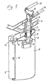
- the high-performance fin rudder or the high-performance rudder nozzle shown in perspective in FIG. 1 is connected to the hull 5 via a rudder shaft 3.
- the rudder shaft 3 is connected to the rigid body 15 of the main rudder blade 1 and can be pivoted by means of a yoke 12 arranged in the hull via two control cylinders 13, 14 connected to a rowing machine, which are connected to the wheelhouse of the ship.
- a fin rudder 2 is articulated on the main rudder blade 1 via articulated connections 16.
- An adjustment housing 6 is arranged above the main rudder blade 1, through which the rudder shaft 3 is guided.
- a rotatable body 8 is provided which can be rotated around the rudder shaft 3 and which is fixed to the coker 4, i.e. H. the watertight implementation of the rudder shaft 3 is connected. This ensures that the rudder post 3 does not come into contact with sea water.
- an eccentric 11 rigidly connected to the fin rudder blade 2 is provided at the upper end of the fin rudder blade 2, located within the adjustment housing 6, an eccentric 11 rigidly connected to the fin rudder blade 2 is provided. which is connected via a hinge 10 to one end of an adjusting rod 7, the other end of which is articulated to a connection point 16, not visible in the perspective illustration, on the rotating body 8.
- the adjustment housing 6 is sealed from sea water by means of a sealing ring carrier 9.
- the cross section shown in FIG. 2 through the high-performance fin rudder according to FIG. 1 shows the connection of the main rudder blade 1 to the rudder shaft 3 and to the adjustment housing 6.
- the rudder shaft 3 is sealed against seawater by means of the coker 4, which is fixed to the hull 5 is welded, the design of the coker 4 corresponds to the design for a normal rudder.
- the rudder shaft 3 is connected to the main rudder blade 1 below the adjustment housing 6 via a screw or welded connection to the strength member 15 of the main rudder blade 1, so that the adjustment housing 6 is arranged outside the strength member of the main rudder blade 1.
- the rotating body 8 is fixed, which has a fixed articulation point 16 with the adjusting rod 7.
- the other end of the adjusting rod 7 is articulated on the eccentric 11 which is firmly connected to the fin rudder blade 2.
- the entire adjustment device for the fin rudder blade 2 ie both the adjusting rod 7 and the coupling points of the adjusting rod 7 on the eccentric 11 on the one hand, and on the rotating body 8 on the other hand, within the connected to the main rudder blade 1 V alternate housing ER 6 and is thus over Sealed sea water.
- the adjustment housing 6 is sealed to the seawater via the sealing ring carrier 9.
- FIG. 3b shows a rotation of the main rudder blade 1 by approximately 45 ° with respect to the longitudinal axis of the ship, as a result of which the fin rudder blade is caused by the articulation of the adjusting rod 7 on the rotating body 8 or on the eccentric 11 2 is rotated by an additional amount compared to the main rudder blade 1.
- the adjustment housing 6 must be made only slightly wider than the housing of the main rudder blade 1, the width of the adjustment housing essentially depending on the maximum possible rudder deflection and the required length of the eccentric rigidly connected to the fin rudder blade 2 11 depends.
- the adjustment rod 7 is advantageously cranked in the region of the articulation point with the rotating body 8, so that at cher effectiveness of the deflection of the fin rudder blade a smaller width of the adjustment housing 6 is achieved.
- FIGS. 4 and 5 show the locking device for the optional forced movement of the fin rudder blade or for the formation of a normal rudder with the fin rudder blade parallel to the main rudder blade.
- the locking device consists of a bolt 20 guided in the koker 4 or ship's hull, which is inserted through a first opening 31 in the koker 4.
- a counterbolt 21 mounted in a housing 23 at the upper end of the main rudder blade 1 is pre-stressed by means of a spring 22, which is also arranged in the housing 23. And presses the counterbolt 21 through a second opening 32 in the upper part of the housing 23.
- a third bore 33 aligned in the rotating body 8 with the first and second bore 31, 32 serves to receive the bolt 20 or counter bolt 21, depending on the position in which the bolt 20 and thus the counter bolt 21 is located.
- the rotating body 8, which is freely rotatable relative to the koker 4, is locked in the illustration according to FIG. 2 with the koker 4 due to the downward movement of the mechanically, electrically or hydraulically driven bolt 20.
- the fin rudder blade is forced relative to the main rudder blade 1. Due to this positive guidance, the fin rudder blade is forced against the main rudder blade 1 when the main rudder blade 1 is adjusted via the rudder shaft 3, so that the high-performance rudder is in operation is.
- the counter pin 21 is held by the pin 20 outside the locking function.
- the bolt 20 has stop shoulders which abut the inner ring of the coke 4, so that a defined downward movement of the bolt 20 is possible.
- the counter-bolt moves under the action of the spring 22 into the rotating body 8, while the bolt 20 remains in the raised position in the area of the coker 4.
- the counter bolt 21 locks the main rudder blade 1 with the rotating body 8, so that the fin rudder blade 2 connected to the rotating body 8 cannot perform any additional movement to the main rudder blade 1, but rather serves as a rearward extension of the main rudder blade 1.
- a normal rudder is thereby formed with a surface which is composed of the surface of the main rudder blade 1 and that of the fin rudder blade 2.
- the bolt 20 and mating bolt 21 have correspondingly designed sliding surfaces at their abutting ends, which are advantageously dome-shaped, so that a corresponding engagement is possible when they move relative to one another.
- the bolt 20, the counter bolt 21 and the bores 31-33 can be designed as sector-shaped cutouts, the sector cutout corresponding to the double rudder deflection.
- the bolt 20, the counter bolt 21 and the bores 31 - 33 are cylindrical, since with a relative movement of the rotating body connected to the koker, in the case of a high-performance rudder, the counter bolt 21 on a corresponding sliding surface of the rotating body and in the straight-ahead position of the main rudder blade abuts against the outer coupling surface of the bolt 20, while in the formation of the normal rudder the bolt 20 against a relative movement of the fin rudder connected to the main rudder blade 1 and thus of the rotating body 8 opposes the end surface of the bolt 20 a corresponding sliding surface in the upper part of the rotating body 8 abuts.
- the pin 20 can be driven either via an adjustment mechanism or hydraulics and via an electromotive actuator. Depending on whether a high-performance fin rudder or a normal rudder is desired, the bolt is retracted or extended and thus the rotating body 8 is optionally locked with the koker 4 or with the main rudder blade 1.
Landscapes
- Chemical & Material Sciences (AREA)
- Engineering & Computer Science (AREA)
- Combustion & Propulsion (AREA)
- Mechanical Engineering (AREA)
- Ocean & Marine Engineering (AREA)
- Toys (AREA)
- Prevention Of Electric Corrosion (AREA)
- Table Devices Or Equipment (AREA)
- Cookers (AREA)
Applications Claiming Priority (4)
| Application Number | Priority Date | Filing Date | Title |
|---|---|---|---|
| DE8421178U | 1984-07-14 | ||
| DE19848421178 DE8421178U1 (de) | 1984-07-14 | 1984-07-14 | Hochleistungs-Flossenruder |
| DE8428287U | 1984-09-26 | ||
| DE19848428287 DE8428287U1 (de) | 1984-09-26 | 1984-09-26 | Hochleistungs-Flossenruder |
Publications (2)
| Publication Number | Publication Date |
|---|---|
| EP0170919A1 true EP0170919A1 (fr) | 1986-02-12 |
| EP0170919B1 EP0170919B1 (fr) | 1989-10-04 |
Family
ID=25949985
Family Applications (1)
| Application Number | Title | Priority Date | Filing Date |
|---|---|---|---|
| EP85108561A Expired EP0170919B1 (fr) | 1984-07-14 | 1985-07-10 | Aileron de haut rendement pour gouvernail |
Country Status (3)
| Country | Link |
|---|---|
| EP (1) | EP0170919B1 (fr) |
| DE (1) | DE3573415D1 (fr) |
| NO (1) | NO162452C (fr) |
Cited By (7)
| Publication number | Priority date | Publication date | Assignee | Title |
|---|---|---|---|---|
| EP1391380A1 (fr) * | 2002-08-22 | 2004-02-25 | Constantino Bandiera | Dispositif mécanique pour la transmission du couple du gouvernail à un volet à l'aide d'un guidage longitudinal |
| WO2008065056A2 (fr) | 2006-11-30 | 2008-06-05 | Van Der Velden Barkemeyer Gmbh | Gouvernail à aileron |
| EP2006201A1 (fr) | 2007-06-21 | 2008-12-24 | Becker Marine Systems GmbH & Co. KG | Gouvernail pour bateaux |
| CN102066193A (zh) * | 2008-06-17 | 2011-05-18 | 马里芬贝黑尔私人有限公司 | 包括舵和螺旋桨的组件 |
| WO2014137222A1 (fr) * | 2013-03-08 | 2014-09-12 | Rolls-Royce Marine As Rudders | Gouvernail |
| CN108639303A (zh) * | 2018-06-13 | 2018-10-12 | 哈尔滨工程大学 | 一种船用转子舵 |
| CN112278223A (zh) * | 2020-11-26 | 2021-01-29 | 大连船舶重工集团舵轴有限公司 | 襟翼舵系统 |
Families Citing this family (2)
| Publication number | Priority date | Publication date | Assignee | Title |
|---|---|---|---|---|
| CN106081042B (zh) * | 2016-08-19 | 2017-12-05 | 无锡市东舟船舶设备股份有限公司 | 带有襟翼的转动导管舵 |
| CN112896481B (zh) * | 2021-04-08 | 2024-07-23 | 上海斯达瑞船舶海洋工程服务有限公司 | 具有止舵功能的船用舵装置 |
Citations (6)
| Publication number | Priority date | Publication date | Assignee | Title |
|---|---|---|---|---|
| DE391119C (de) | 1921-03-31 | 1924-02-28 | Anton Flettner | Steueranordnung fuer Luft- und Wasserfahrzeuge |
| CH467190A (de) | 1966-12-29 | 1969-01-15 | Broehl Walter | Schiffssteuerruder |
| DE2656738A1 (de) | 1976-12-15 | 1978-06-22 | Jastram Werke | Ruder mit einer flosse fuer wasserfahrzeuge |
| DE7829008U1 (de) | 1980-03-13 | Willi Becker Ingenieurbuero Gmbh, 2000 Hamburg | Mittels eines Antriebes verstellbarer, mehrteiliger Strömungskörper zum Steuern von Wasserfahrzeugen | |
| EP0051822A1 (fr) | 1980-10-30 | 1982-05-19 | Willi Becker Ingenieurbüro GmbH | Gouvernail pour navires |
| DE3150992A1 (de) | 1981-01-15 | 1983-07-14 | Jastram-Werke GmbH & Co KG, 2050 Hamburg | "ruder fuer wasserfahrzeuge" |
-
1985
- 1985-07-10 DE DE8585108561T patent/DE3573415D1/de not_active Expired
- 1985-07-10 EP EP85108561A patent/EP0170919B1/fr not_active Expired
- 1985-07-15 NO NO852824A patent/NO162452C/no not_active IP Right Cessation
Patent Citations (6)
| Publication number | Priority date | Publication date | Assignee | Title |
|---|---|---|---|---|
| DE7829008U1 (de) | 1980-03-13 | Willi Becker Ingenieurbuero Gmbh, 2000 Hamburg | Mittels eines Antriebes verstellbarer, mehrteiliger Strömungskörper zum Steuern von Wasserfahrzeugen | |
| DE391119C (de) | 1921-03-31 | 1924-02-28 | Anton Flettner | Steueranordnung fuer Luft- und Wasserfahrzeuge |
| CH467190A (de) | 1966-12-29 | 1969-01-15 | Broehl Walter | Schiffssteuerruder |
| DE2656738A1 (de) | 1976-12-15 | 1978-06-22 | Jastram Werke | Ruder mit einer flosse fuer wasserfahrzeuge |
| EP0051822A1 (fr) | 1980-10-30 | 1982-05-19 | Willi Becker Ingenieurbüro GmbH | Gouvernail pour navires |
| DE3150992A1 (de) | 1981-01-15 | 1983-07-14 | Jastram-Werke GmbH & Co KG, 2050 Hamburg | "ruder fuer wasserfahrzeuge" |
Cited By (10)
| Publication number | Priority date | Publication date | Assignee | Title |
|---|---|---|---|---|
| EP1391380A1 (fr) * | 2002-08-22 | 2004-02-25 | Constantino Bandiera | Dispositif mécanique pour la transmission du couple du gouvernail à un volet à l'aide d'un guidage longitudinal |
| WO2008065056A2 (fr) | 2006-11-30 | 2008-06-05 | Van Der Velden Barkemeyer Gmbh | Gouvernail à aileron |
| EP2006201A1 (fr) | 2007-06-21 | 2008-12-24 | Becker Marine Systems GmbH & Co. KG | Gouvernail pour bateaux |
| US8117979B2 (en) | 2007-06-21 | 2012-02-21 | Becker Marine Systems Gmbh & Co. | Rudder for ships |
| KR101118450B1 (ko) * | 2007-06-21 | 2012-03-06 | 베커 마린 시스템즈 게엠베하 운트 콤파니 카게 | 선박용 러더 |
| CN101327842B (zh) * | 2007-06-21 | 2012-05-30 | 贝克船舶系统有限及两合公司 | 船用舵 |
| CN102066193A (zh) * | 2008-06-17 | 2011-05-18 | 马里芬贝黑尔私人有限公司 | 包括舵和螺旋桨的组件 |
| WO2014137222A1 (fr) * | 2013-03-08 | 2014-09-12 | Rolls-Royce Marine As Rudders | Gouvernail |
| CN108639303A (zh) * | 2018-06-13 | 2018-10-12 | 哈尔滨工程大学 | 一种船用转子舵 |
| CN112278223A (zh) * | 2020-11-26 | 2021-01-29 | 大连船舶重工集团舵轴有限公司 | 襟翼舵系统 |
Also Published As
| Publication number | Publication date |
|---|---|
| NO162452C (no) | 1996-11-06 |
| NO162452B (no) | 1989-09-25 |
| EP0170919B1 (fr) | 1989-10-04 |
| DE3573415D1 (en) | 1989-11-09 |
| NO852824L (no) | 1986-01-15 |
Similar Documents
| Publication | Publication Date | Title |
|---|---|---|
| EP2006201B1 (fr) | Gouvernail pour bateaux | |
| DE3885105T2 (de) | Kombinierte ruder- und schraubenanordnung. | |
| EP0170919B1 (fr) | Aileron de haut rendement pour gouvernail | |
| DE2828270C2 (de) | Vorrichtung zur begrenzten Drehung einer Welle um eine Rotationsachse | |
| DE2709666C2 (de) | 5-gliederiges Getriebe zum Verstellen eines Hauptruders mit Flosse für Wasserfahrzeuge | |
| DE2928929C2 (de) | Antrieb für schwimmfähige Fahrzeuge, insbesondere Amphibienfahrzeuge | |
| DE3101042C2 (de) | Ruder für Wasserfahrzeuge | |
| DE2202006A1 (de) | Stellvorrichtung fuer ein Schiffsruderblatt | |
| DE2914974A1 (de) | Auftriebsklappen, insbesondere an flugzeugtragfluegeln | |
| DE2656738C3 (de) | Ruder für Wasserfahrzeuge | |
| DE2318234C2 (de) | Schwenk- und Trimmeinrichtung für einen Bootsantrieb | |
| DE2655126C3 (de) | Antrieb für Wasserfahrzeuge | |
| DE8428287U1 (de) | Hochleistungs-Flossenruder | |
| DE8613505U1 (de) | Ruder für Schiffe, insbesondere für schwerfällige, schwer manövrierfähige Yachten mit fischkutterähnlichen Schiffskörpern, Motorsegler und Motorboote | |
| DE8421178U1 (de) | Hochleistungs-Flossenruder | |
| DE2703302C3 (de) | Steuervorrichtung für Zykloidenpropeller | |
| AT524490B1 (de) | Rudereinrichtung für ein Wasserfahrzeug | |
| DE19841392B4 (de) | Hochlast-Schweberuder | |
| DE102023103813B3 (de) | Selbststeuervorrichtung für Wasserfahrzeuge | |
| DE2246766C3 (de) | Steuereinrichtung für Schiffe | |
| DE3490665C2 (de) | Schiffsruderanlage | |
| DE7829008U1 (de) | Mittels eines Antriebes verstellbarer, mehrteiliger Strömungskörper zum Steuern von Wasserfahrzeugen | |
| AT205368B (de) | Steuerruder für Schiffe | |
| DE3842172A1 (de) | Hochleistungs-ruderduese | |
| DE202011005332U1 (de) | Schiff und Ruder für ein derartiges Schiff |
Legal Events
| Date | Code | Title | Description |
|---|---|---|---|
| PUAI | Public reference made under article 153(3) epc to a published international application that has entered the european phase |
Free format text: ORIGINAL CODE: 0009012 |
|
| AK | Designated contracting states |
Designated state(s): DE GB NL |
|
| 17P | Request for examination filed |
Effective date: 19860807 |
|
| RIN1 | Information on inventor provided before grant (corrected) |
Inventor name: RATHMANN WERNER |
|
| 17Q | First examination report despatched |
Effective date: 19880812 |
|
| GRAA | (expected) grant |
Free format text: ORIGINAL CODE: 0009210 |
|
| AK | Designated contracting states |
Kind code of ref document: B1 Designated state(s): DE GB NL |
|
| REF | Corresponds to: |
Ref document number: 3573415 Country of ref document: DE Date of ref document: 19891109 |
|
| GBT | Gb: translation of ep patent filed (gb section 77(6)(a)/1977) | ||
| PLBI | Opposition filed |
Free format text: ORIGINAL CODE: 0009260 |
|
| 26 | Opposition filed |
Opponent name: ULSTEIN TRADING LTD, A/S Effective date: 19900515 |
|
| NLR1 | Nl: opposition has been filed with the epo |
Opponent name: ULSTEIN TRADING LTD, A/S |
|
| PLAB | Opposition data, opponent's data or that of the opponent's representative modified |
Free format text: ORIGINAL CODE: 0009299OPPO |
|
| R26 | Opposition filed (corrected) |
Opponent name: ULSTEIN INTERNATIONAL AS Effective date: 19900515 |
|
| NLXE | Nl: other communications concerning ep-patents (part 3 heading xe) |
Free format text: IN PAT.BUL.16/90,CORR.:ULSTEIN INTERNATIONAL AS |
|
| PLBN | Opposition rejected |
Free format text: ORIGINAL CODE: 0009273 |
|
| STAA | Information on the status of an ep patent application or granted ep patent |
Free format text: STATUS: OPPOSITION REJECTED |
|
| 27O | Opposition rejected |
Effective date: 19940503 |
|
| NLR2 | Nl: decision of opposition | ||
| REG | Reference to a national code |
Ref country code: GB Ref legal event code: IF02 |
|
| PGFP | Annual fee paid to national office [announced via postgrant information from national office to epo] |
Ref country code: DE Payment date: 20040621 Year of fee payment: 20 |
|
| PGFP | Annual fee paid to national office [announced via postgrant information from national office to epo] |
Ref country code: GB Payment date: 20040705 Year of fee payment: 20 |
|
| PGFP | Annual fee paid to national office [announced via postgrant information from national office to epo] |
Ref country code: NL Payment date: 20040722 Year of fee payment: 20 |
|
| PG25 | Lapsed in a contracting state [announced via postgrant information from national office to epo] |
Ref country code: GB Free format text: LAPSE BECAUSE OF EXPIRATION OF PROTECTION Effective date: 20050709 |
|
| PG25 | Lapsed in a contracting state [announced via postgrant information from national office to epo] |
Ref country code: NL Free format text: LAPSE BECAUSE OF EXPIRATION OF PROTECTION Effective date: 20050710 |
|
| REG | Reference to a national code |
Ref country code: GB Ref legal event code: PE20 |
|
| NLV7 | Nl: ceased due to reaching the maximum lifetime of a patent |
Effective date: 20050710 |
|
| APAH | Appeal reference modified |
Free format text: ORIGINAL CODE: EPIDOSCREFNO |