EP0170948B1 - Regler für einen Kühler nach dem Joule-Thomsoneffekt - Google Patents
Regler für einen Kühler nach dem Joule-Thomsoneffekt Download PDFInfo
- Publication number
- EP0170948B1 EP0170948B1 EP85108979A EP85108979A EP0170948B1 EP 0170948 B1 EP0170948 B1 EP 0170948B1 EP 85108979 A EP85108979 A EP 85108979A EP 85108979 A EP85108979 A EP 85108979A EP 0170948 B1 EP0170948 B1 EP 0170948B1
- Authority
- EP
- European Patent Office
- Prior art keywords
- needle
- rod
- tubular casing
- cylindrical
- gas
- Prior art date
- Legal status (The legal status is an assumption and is not a legal conclusion. Google has not performed a legal analysis and makes no representation as to the accuracy of the status listed.)
- Expired
Links
Images

Classifications
-
- G—PHYSICS
- G05—CONTROLLING; REGULATING
- G05D—SYSTEMS FOR CONTROLLING OR REGULATING NON-ELECTRIC VARIABLES
- G05D23/00—Control of temperature
- G05D23/01—Control of temperature without auxiliary power
- G05D23/02—Control of temperature without auxiliary power with sensing element expanding and contracting in response to changes of temperature
- G05D23/024—Control of temperature without auxiliary power with sensing element expanding and contracting in response to changes of temperature the sensing element being of the rod type, tube type, or of a similar type
-
- F—MECHANICAL ENGINEERING; LIGHTING; HEATING; WEAPONS; BLASTING
- F25—REFRIGERATION OR COOLING; COMBINED HEATING AND REFRIGERATION SYSTEMS; HEAT PUMP SYSTEMS; MANUFACTURE OR STORAGE OF ICE; LIQUEFACTION SOLIDIFICATION OF GASES
- F25B—REFRIGERATION MACHINES, PLANTS OR SYSTEMS; COMBINED HEATING AND REFRIGERATION SYSTEMS; HEAT PUMP SYSTEMS
- F25B9/00—Compression machines, plants or systems, in which the refrigerant is air or other gas of low boiling point
- F25B9/02—Compression machines, plants or systems, in which the refrigerant is air or other gas of low boiling point using Joule-Thompson effect; using vortex effect
-
- F—MECHANICAL ENGINEERING; LIGHTING; HEATING; WEAPONS; BLASTING
- F25—REFRIGERATION OR COOLING; COMBINED HEATING AND REFRIGERATION SYSTEMS; HEAT PUMP SYSTEMS; MANUFACTURE OR STORAGE OF ICE; LIQUEFACTION SOLIDIFICATION OF GASES
- F25B—REFRIGERATION MACHINES, PLANTS OR SYSTEMS; COMBINED HEATING AND REFRIGERATION SYSTEMS; HEAT PUMP SYSTEMS
- F25B2309/00—Gas cycle refrigeration machines
- F25B2309/02—Gas cycle refrigeration machines using the Joule-Thompson effect
- F25B2309/022—Gas cycle refrigeration machines using the Joule-Thompson effect characterised by the expansion element
Definitions
- the invention relates to Joule-Thomson effect coolers using the expansion of a high pressure gas to produce very low temperatures.
- Such coolers are used in particular to cool infrared detectors on board vehicles at very low temperatures.
- the source of pressurized gas is generally a high-pressure nitrogen tank located on board the machine and making it possible to cool the infrared cell to the nitrogen liquefaction temperature, which is 77 ° K, starting from the gas at room temperature. It is understood that for such an application it is necessary to have extremely precise regulation to allow both very rapid cooling and minimal nitrogen consumption once the desired temperature is reached. In fact, this consumption determines both the weight of the on-board nitrogen tank and the operating time.
- such regulators necessarily include an expandable member which actuates the closing of a needle when the temperature drops.
- an expandable member which actuates the closing of a needle when the temperature drops.
- a relatively elastic expandable member such as a metal bellows filled with an expandable gas, as described in document FR-A-2 265 048, or even a bimetallic strip working in bending.
- Such devices cannot be suitable for the application envisaged by the fact that, due to the high elasticity of the expandable member, the regulation is greatly influenced by the gas pressure prevailing under the needle.
- the needle In addition, with these prior regulating devices, during the initial cooling, the needle generally succeeds in closing completely or partially due to the energetic cooling of the cold point, which is, as we have seen, the seat of the needle, before the organ to be cooled has reached the desired low temperature. In other words, pumping takes place even more during cooling and increases the duration thereof, which, as we have seen, is a major drawback for the intended application.
- the object of the invention is to eliminate the above drawbacks by providing a longitudinally expandable metal rod cooler regulator which simultaneously provides rapid cooling and precise regulation without pumping.
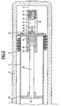
- the cryostat 1 is constituted by a Dewar vessel formed by an external envelope 2 and an internal envelope 3 separated by the vacuum, the interior envelope 3 having internally in its bottom the organ to be cooled 4 constituted for example by an infrared detection cell activated by radiation through the bottom walls of the cryostat 1.
- a Joule-Thomson effect cooler is used in known manner comprising a connection end piece 5 which is connected by its threaded end 6 to a pressurized nitrogen inlet, generally coming from a pressure tank. .
- a tubular casing 7 around which is wound, according to a known technique, an exchanger tube 8 of very small diameter with, around this tube and around the tubular casing 7 respectively, turns d 'spacing and baffling as well as timing, these various elements quite conventional being visible in Figure 2 but not referenced.
- one end 9 of the tube 8 is tightly connected with the connection nozzle 5 on the side of the gas inlet at room temperature, and its other end 10 passes through the tubular casing 7 according to a diameter, the tube is ending with a plugged end.
- On this rectilinear diametrical part 10 is fixed a very small cylindrical body 11 pierced with a diametral hole for the passage of the part 10 and an axial hole 12 which also passes through the part 10 of the tube and which serves as a seat for the needle .
- the two ends of the tube 10 are welded to the tubular casing 7 and the part 11 is itself welded to the center of this part 10 and counter-drilled in the extension of the hole 12.
- a needle 13 is used in a known manner, the point 14 of which penetrates into the hole 12.
- this needle 13 is simply constituted by a cylindrical-conical piece, with however preferably a flat 15 or a hollow made according to a generatirce of the cone and over a penetration depth of about 7 microns.
- a fork 16 is used consisting of a cylindrical piece having an axial bore adjusting with the desired clearance at the cylindrical periphery of the seat 11 as well as the needle 13, while a threaded end 17 receives a screw adjustment 18 acting by simple contact on this needle 13 without being integral.
- the cylindrical wall of the fork 16 also has two diametrical slots 19 of sufficient width to allow free passage of the straight portion 10 of the tube 8.
- a cylindrical rod 20 for example brass, is used as the expandable member, for example to facilitate brazing or welding, while all the other metal parts described above are made of Invar alloy, especially 5, 7, 11, 13, 16 and 18.
- one end 21 of this rod is mechanically fixed and thermally connected by soldering or welding and by means of a partition 22, preferably also an Invar, to the inner wall of the tubular casing 7 in a point thereof which, as it appears in Figure 1, is between the hot end 9 and the cold end 10 of the exchanger tube 8.
- the other end 23 of this rod 20 is also fixed by brazing or welding to the head of the cylindrical fork 16.
- the cylindrical rod 20 as well as the cylindrical fork 16, which are coaxial with the tubular casing 7, each have a diameter sufficiently reduced to allow a large annular gap to remain between their cylindrical periphery and the inner cylindrical periphery of the tube 7.
- thermal insulation 24 constituted for example by natural cotton, to fill this gap and eliminate all convection movements, both longitudinal and transverse, between the cold point 11 and the rest of the exchanger.
- the invention achieves faster cooling initial, and also precise regulation without pumping, even for ambient temperatures varying from -40 ° C to + 80 ° C.
- the gas continues to arrive by 9 at room temperature and therefore practically brings calories to the partition 22, therefore to the end 21 of the rod 20, while its other end 23 is cooled only by the thermal bridge formed by the fork 16. It is therefore, unlike the usual device, that with a significant delay that the regulation comes into play , namely when the liquefaction temperature has increased widely over the length of the tube-casing 7 from the outside thereof.
- This superpower start-up allows the device produced using this technique to cool the room temperature down to the liquefaction temperature in as short as 2 to 3 seconds.
- the needle 13 can be adjusted by means of the screw 18 so that this needle is closed for an ambient temperature of 20 ° C. and once the device has been cooled. In this way, for ambient temperatures between 20 ° C and -40 ° C, this needle remains closed, and the regulation uses in this case the phenomenon of secondary regulation explained above, thanks to the presence of the dish 15 and to the variation in the length of capillary tube 8 interested in the liquid phase, which is enough to reduce the consumption of gas when the ambient temperature decreases (high altitude for example).
- the regulation intervenes by the expansion or a lesser contraction of the rod 20, thanks to the thermal bridging indicated and according to the progression of the cold at one end and the arrival of the ambient temperature at the other end, thus taking into account both the current state of the temperature and the foreseeable power.
- the invention easily allows extreme miniaturization of the entire cryostat, therefore a corresponding reduction in consumption.
Landscapes
- Engineering & Computer Science (AREA)
- Physics & Mathematics (AREA)
- General Physics & Mathematics (AREA)
- Automation & Control Theory (AREA)
- Mechanical Engineering (AREA)
- Thermal Sciences (AREA)
- General Engineering & Computer Science (AREA)
Claims (4)
Applications Claiming Priority (2)
| Application Number | Priority Date | Filing Date | Title |
|---|---|---|---|
| FR8412096 | 1984-07-30 | ||
| FR8412096A FR2568385B1 (fr) | 1984-07-30 | 1984-07-30 | Regulateur de refroidisseur a effet joule-thomson |
Publications (2)
| Publication Number | Publication Date |
|---|---|
| EP0170948A1 EP0170948A1 (de) | 1986-02-12 |
| EP0170948B1 true EP0170948B1 (de) | 1987-09-16 |
Family
ID=9306638
Family Applications (1)
| Application Number | Title | Priority Date | Filing Date |
|---|---|---|---|
| EP85108979A Expired EP0170948B1 (de) | 1984-07-30 | 1985-07-18 | Regler für einen Kühler nach dem Joule-Thomsoneffekt |
Country Status (4)
| Country | Link |
|---|---|
| US (1) | US4569210A (de) |
| EP (1) | EP0170948B1 (de) |
| DE (1) | DE3560652D1 (de) |
| FR (1) | FR2568385B1 (de) |
Families Citing this family (8)
| Publication number | Priority date | Publication date | Assignee | Title |
|---|---|---|---|---|
| US4781033A (en) * | 1987-07-16 | 1988-11-01 | Apd Cryogenics | Heat exchanger for a fast cooldown cryostat |
| FR2642510B1 (fr) * | 1989-02-02 | 1995-06-16 | Albagnac Rene | Regulateur de debit de gaz pour refroidisseur a effet joule-thomson |
| FR2645256B1 (fr) * | 1989-03-15 | 1994-12-23 | Air Liquide | Refroidisseur joule-thomson a deux debits |
| FI96064C (fi) * | 1992-07-15 | 1996-04-25 | Outokumpu Instr Oy | Menetelmä jäähdytyksen aikaansaamiseksi ja jäähdytykseen soveltuva jäähdytyslaite |
| GB2270738B (en) * | 1992-08-25 | 1996-08-07 | Israel State | Fluid flow regulator |
| GB9509861D0 (en) * | 1995-05-16 | 1995-07-12 | British Steel Plc | Annular separators for double walled pipe structures |
| US5819548A (en) * | 1996-11-01 | 1998-10-13 | Clawson; Lawrence G. | Thermal expansion valve and system including such device and method for making such device |
| FR2833073B1 (fr) | 2001-12-05 | 2004-05-21 | Air Liquide | Systeme de controle de debit de fluide cryogenique et refroidisseur joule-thomson comportant un tel systeme de controle |
Citations (1)
| Publication number | Priority date | Publication date | Assignee | Title |
|---|---|---|---|---|
| FR2377588A1 (fr) * | 1977-01-13 | 1978-08-11 | Hymatic Eng Co Ltd | Appareil de refroidissement cryogenique |
Family Cites Families (17)
| Publication number | Priority date | Publication date | Assignee | Title |
|---|---|---|---|---|
| US1719075A (en) * | 1927-07-01 | 1929-07-02 | Copeland Products Inc | Regulating mechanism |
| US2312671A (en) * | 1940-12-19 | 1943-03-02 | Johnson Service Co | Thermostatic and like unit |
| US2398262A (en) * | 1944-03-20 | 1946-04-09 | Richard H Swart | Refrigerating apparatus |
| US3273356A (en) * | 1964-09-28 | 1966-09-20 | Little Inc A | Heat exchanger-expander adapted to deliver refrigeration |
| US3320755A (en) * | 1965-11-08 | 1967-05-23 | Air Prod & Chem | Cryogenic refrigeration system |
| US3375975A (en) * | 1966-03-21 | 1968-04-02 | Vapor Corp | Pneumatic temperature sensing probe |
| GB1230079A (de) * | 1967-06-28 | 1971-04-28 | Hymatic Eng Co Ltd | |
| US3517525A (en) * | 1967-06-28 | 1970-06-30 | Hymatic Eng Co Ltd | Cooling apparatus employing the joule-thomson effect |
| US3457730A (en) * | 1967-10-02 | 1969-07-29 | Hughes Aircraft Co | Throttling valve employing the joule-thomson effect |
| US3613689A (en) * | 1970-01-13 | 1971-10-19 | Frigitronics Of Conn Inc | Cryosurgical apparatus |
| FR2176544B1 (de) * | 1972-03-23 | 1982-02-19 | Air Liquide | |
| FR2265048A2 (en) * | 1974-03-19 | 1975-10-17 | Air Liquide | Joule-Thomson type refrigerator control method - uses flow regulation fluid expanded by increase in temp. of refrigerant |
| US4002039A (en) * | 1975-08-28 | 1977-01-11 | The Bendix Corporation | Self-regulating cryostat |
| US4152903A (en) * | 1978-04-13 | 1979-05-08 | Air Products And Chemicals, Inc. | Bimaterial demand flow cryostat |
| GB2085139A (en) * | 1980-10-10 | 1982-04-21 | Hymatic Engineering The Co Ltd | Cryogenic cooling apparatus |
| FR2509448A1 (fr) * | 1981-07-07 | 1983-01-14 | Telecommunications Sa | Dispositif de regulation d'un refrigerateur a effet joule thomson |
| FR2520131B1 (fr) * | 1982-01-19 | 1985-09-20 | Telecommunications Sa | Dispositif de regulation d'un refrigerateur a effet joule-thomson |
-
1984
- 1984-07-30 FR FR8412096A patent/FR2568385B1/fr not_active Expired
-
1985
- 1985-07-18 EP EP85108979A patent/EP0170948B1/de not_active Expired
- 1985-07-18 DE DE8585108979T patent/DE3560652D1/de not_active Expired
- 1985-07-23 US US06/758,058 patent/US4569210A/en not_active Expired - Fee Related
Patent Citations (1)
| Publication number | Priority date | Publication date | Assignee | Title |
|---|---|---|---|---|
| FR2377588A1 (fr) * | 1977-01-13 | 1978-08-11 | Hymatic Eng Co Ltd | Appareil de refroidissement cryogenique |
Also Published As
| Publication number | Publication date |
|---|---|
| US4569210A (en) | 1986-02-11 |
| DE3560652D1 (en) | 1987-10-22 |
| FR2568385A1 (fr) | 1986-01-31 |
| EP0170948A1 (de) | 1986-02-12 |
| FR2568385B1 (fr) | 1986-09-26 |
Similar Documents
| Publication | Publication Date | Title |
|---|---|---|
| US5119637A (en) | Ultra-high temperature stability Joule-Thomson cooler with capability to accommodate pressure variations | |
| CA1043113A (en) | Self regulating cryostat | |
| EP0170948A1 (de) | Regler für einen Kühler nach dem Joule-Thomsoneffekt | |
| EP0181796B1 (de) | Kryogengemischbehälter und Verfahren zum Abzapfen der Flüssigkeit | |
| US4152903A (en) | Bimaterial demand flow cryostat | |
| US4177650A (en) | Cryogenic cooling apparatus | |
| EP0084308B1 (de) | Regelvorrichtung für eine nach dem Joule-Thomson-Effekt arbeitende Kühleinrichtung | |
| EP0388277B1 (de) | Joule-Thomson-Kühlvorrichtung | |
| FR2776762A1 (fr) | Dispositif de liaison thermique pour machine cryogenique | |
| US4373357A (en) | Cryogenic cooling apparatus | |
| US4237699A (en) | Variable flow cryostat with dual orifice | |
| EP0245164B1 (de) | Joule-Thomson-Kühler | |
| EP0173599B1 (de) | Sonde zum Kühlen nach dem Joule-Thomsoneffekt | |
| FR2642510A1 (fr) | Regulateur de debit de gaz pour refroidisseur a effet joule-thomson | |
| EP0305257B1 (de) | Verfahren und Vorrichtung zur Kryokühlung eines Objekts | |
| FR2558938A1 (fr) | Appareil de refroidissement cryogenique | |
| US3983714A (en) | Cryostat system for temperatures on the order of 2°K or less | |
| EP0643254A1 (de) | Lagerbehälter für Hochdruckgas sowie Anlage für die Lagerung und Lieferung von Hochdruckgas | |
| EP1482259A1 (de) | Entspannungsvorrichtung für Klimakreislauf | |
| EP1295074A1 (de) | Vorrichtung zur thermischen stabilisierung eines zu kühlenden objektes | |
| FR2651151A1 (fr) | Procede d'elaboration et de stockage d'un melange de freon et d'anhydride carbonique. | |
| WO2005012810A1 (fr) | Dispositif pour l’adaptation d’un detendeur a l’evaporateur d’un appareil de climatisation | |
| JP2562622B2 (ja) | 試料低温装置 | |
| EP0247935B1 (de) | Zuleitungsverfahren für einen Joule-Thomson-Kühler und Kühlvorrichtung zu seiner Durchführung | |
| EP0286462A1 (de) | Miniatur-Kühler mit Joule-Thomson-Entspannung und Verfahren zu seiner Herstellung |
Legal Events
| Date | Code | Title | Description |
|---|---|---|---|
| PUAI | Public reference made under article 153(3) epc to a published international application that has entered the european phase |
Free format text: ORIGINAL CODE: 0009012 |
|
| AK | Designated contracting states |
Designated state(s): DE GB |
|
| 17P | Request for examination filed |
Effective date: 19860321 |
|
| 17Q | First examination report despatched |
Effective date: 19860805 |
|
| GRAA | (expected) grant |
Free format text: ORIGINAL CODE: 0009210 |
|
| AK | Designated contracting states |
Kind code of ref document: B1 Designated state(s): DE GB |
|
| REF | Corresponds to: |
Ref document number: 3560652 Country of ref document: DE Date of ref document: 19871022 |
|
| GBT | Gb: translation of ep patent filed (gb section 77(6)(a)/1977) | ||
| PLBE | No opposition filed within time limit |
Free format text: ORIGINAL CODE: 0009261 |
|
| STAA | Information on the status of an ep patent application or granted ep patent |
Free format text: STATUS: NO OPPOSITION FILED WITHIN TIME LIMIT |
|
| 26N | No opposition filed | ||
| PGFP | Annual fee paid to national office [announced via postgrant information from national office to epo] |
Ref country code: GB Payment date: 19940712 Year of fee payment: 10 |
|
| PGFP | Annual fee paid to national office [announced via postgrant information from national office to epo] |
Ref country code: DE Payment date: 19940721 Year of fee payment: 10 |
|
| PG25 | Lapsed in a contracting state [announced via postgrant information from national office to epo] |
Ref country code: GB Effective date: 19950718 |
|
| GBPC | Gb: european patent ceased through non-payment of renewal fee |
Effective date: 19950718 |
|
| PG25 | Lapsed in a contracting state [announced via postgrant information from national office to epo] |
Ref country code: DE Effective date: 19960402 |