EP0171012B1 - Dispositif acousto-optique et méthode pour sa fabrication - Google Patents
Dispositif acousto-optique et méthode pour sa fabrication Download PDFInfo
- Publication number
- EP0171012B1 EP0171012B1 EP19850109518 EP85109518A EP0171012B1 EP 0171012 B1 EP0171012 B1 EP 0171012B1 EP 19850109518 EP19850109518 EP 19850109518 EP 85109518 A EP85109518 A EP 85109518A EP 0171012 B1 EP0171012 B1 EP 0171012B1
- Authority
- EP
- European Patent Office
- Prior art keywords
- base body
- optical
- layer
- acoustic
- acousto
- Prior art date
- Legal status (The legal status is an assumption and is not a legal conclusion. Google has not performed a legal analysis and makes no representation as to the accuracy of the status listed.)
- Expired - Lifetime
Links
- 238000004519 manufacturing process Methods 0.000 title claims description 11
- 239000000463 material Substances 0.000 claims description 29
- 230000003287 optical effect Effects 0.000 claims description 28
- 230000008878 coupling Effects 0.000 claims description 9
- 238000010168 coupling process Methods 0.000 claims description 9
- 238000005859 coupling reaction Methods 0.000 claims description 9
- 229910052751 metal Inorganic materials 0.000 claims description 6
- 239000002184 metal Substances 0.000 claims description 6
- LAJZODKXOMJMPK-UHFFFAOYSA-N tellurium dioxide Chemical compound O=[Te]=O LAJZODKXOMJMPK-UHFFFAOYSA-N 0.000 claims description 5
- GQYHUHYESMUTHG-UHFFFAOYSA-N lithium niobate Chemical compound [Li+].[O-][Nb](=O)=O GQYHUHYESMUTHG-UHFFFAOYSA-N 0.000 claims description 4
- 239000004020 conductor Substances 0.000 claims description 2
- 230000002452 interceptive effect Effects 0.000 claims 3
- 230000003993 interaction Effects 0.000 description 28
- 238000005520 cutting process Methods 0.000 description 8
- 230000000694 effects Effects 0.000 description 8
- 230000008901 benefit Effects 0.000 description 3
- 230000008859 change Effects 0.000 description 3
- 238000000034 method Methods 0.000 description 2
- 230000001902 propagating effect Effects 0.000 description 2
- 239000012780 transparent material Substances 0.000 description 2
- 239000002699 waste material Substances 0.000 description 2
- 229910003327 LiNbO3 Inorganic materials 0.000 description 1
- 230000004913 activation Effects 0.000 description 1
- 239000011230 binding agent Substances 0.000 description 1
- 238000007640 computer printing Methods 0.000 description 1
- 239000007772 electrode material Substances 0.000 description 1
- 230000007246 mechanism Effects 0.000 description 1
- 230000000737 periodic effect Effects 0.000 description 1
- 230000007480 spreading Effects 0.000 description 1
- 238000003892 spreading Methods 0.000 description 1
- 239000000126 substance Substances 0.000 description 1
- 238000002604 ultrasonography Methods 0.000 description 1
Images


Classifications
-
- G—PHYSICS
- G02—OPTICS
- G02F—OPTICAL DEVICES OR ARRANGEMENTS FOR THE CONTROL OF LIGHT BY MODIFICATION OF THE OPTICAL PROPERTIES OF THE MEDIA OF THE ELEMENTS INVOLVED THEREIN; NON-LINEAR OPTICS; FREQUENCY-CHANGING OF LIGHT; OPTICAL LOGIC ELEMENTS; OPTICAL ANALOGUE/DIGITAL CONVERTERS
- G02F1/00—Devices or arrangements for the control of the intensity, colour, phase, polarisation or direction of light arriving from an independent light source, e.g. switching, gating or modulating; Non-linear optics
- G02F1/01—Devices or arrangements for the control of the intensity, colour, phase, polarisation or direction of light arriving from an independent light source, e.g. switching, gating or modulating; Non-linear optics for the control of the intensity, phase, polarisation or colour
- G02F1/11—Devices or arrangements for the control of the intensity, colour, phase, polarisation or direction of light arriving from an independent light source, e.g. switching, gating or modulating; Non-linear optics for the control of the intensity, phase, polarisation or colour based on acousto-optical elements, e.g. using variable diffraction by sound or like mechanical waves
-
- G—PHYSICS
- G02—OPTICS
- G02F—OPTICAL DEVICES OR ARRANGEMENTS FOR THE CONTROL OF LIGHT BY MODIFICATION OF THE OPTICAL PROPERTIES OF THE MEDIA OF THE ELEMENTS INVOLVED THEREIN; NON-LINEAR OPTICS; FREQUENCY-CHANGING OF LIGHT; OPTICAL LOGIC ELEMENTS; OPTICAL ANALOGUE/DIGITAL CONVERTERS
- G02F1/00—Devices or arrangements for the control of the intensity, colour, phase, polarisation or direction of light arriving from an independent light source, e.g. switching, gating or modulating; Non-linear optics
- G02F1/29—Devices or arrangements for the control of the intensity, colour, phase, polarisation or direction of light arriving from an independent light source, e.g. switching, gating or modulating; Non-linear optics for the control of the position or the direction of light beams, i.e. deflection
- G02F1/33—Acousto-optical deflection devices
Definitions
- the invention relates to an acousto-optical device according to the preamble of claim 1 and a method for its production.
- an acousto-optical device with a base body made of an interaction material for coupling acoustic pressure waves with optical waves in which the base body has an optical window for coupling an optical wave and an acoustic interface for coupling an acoustic pressure wave into the Has base body.
- the device also has a transducer layer connected flatly to the acoustic interface of the base body by an intermediate bonding layer made of electrically conductive material for generating the acoustic pressure wave coupled into the base body by the bonding layer by applying an electrical signal between a metal electrode layer applied to the transducer layer and one on the side exposed strips of the binder layer on the converter layer.
- the metal electrode layer completely covers the converter layer.
- the object of the invention is to improve a device of the type mentioned in such a way that the acoustic pressure wave fronts fill a larger volume of the base body.
- the acousto-optical effect refers to the interaction of optical waves with acoustic waves in an interaction material.
- One result of this interaction is that the optical waves are diffracted in certain directions or orders, similar to a blazed diffraction grating.
- This effect enables an optical variable to be controlled or manipulated by manipulating another variable, namely an acoustic wave.
- an acousto-optical device combines the following three components.
- An interaction medium in which the optical waves and the acoustic waves or ultrasound waves interact a transducer which generates the acousto-optical waves and from which these waves are coupled into the interaction medium, and electrodes by which electrical power is applied to the transducer and which Get transducers to generate acoustic waves.
- the acoustic properties of the transducer are affected by the type or type and size of the electrical input signal, it is easy to see that ultimately the optical waves entering the interaction medium are electrically controlled.
- acousto-optic devices have been increasingly used for laser beam control.
- Laser computer printing systems, laser plate making, video plate recording, facsimile systems, and various other applications are associated with acousto-optical devices.
- an acousto-optical modulator is made from a material that has a high acousto-optical dynamic range, for example from a crystalline tellurium dioxide (TeO2), with which a piezoelectric transducer material, such as lithium niobate (LiNbO3), is connected.
- a radio or radio frequency source connected to the device by electrodes excites the transducer to vibrate. These vibrations are coupled into the acousto-optical material through binding layers, where they spread as acoustic pressure waves and cause periodic variations in the refractive index of the medium. The variations have the same frequency as the high frequency source and are in phase with it.
- the incident rays for example a Bragg angle laser beam are properly focused with respect to the acoustic wave fronts in the medium, part of the optical power is diffracted at an angle which is twice the Bragg angle.
- a phase grating which is indicated as lines 12, is formed within a base body 14 of optically transparent material by electrical activation of a converter 10.
- the phase grating 12 is generated by a change in the refractive index due to the so-called photoelastic or electrical effect. The magnitude of this change depends on the sound amplitude and the size of the photoelectric effect of the special material. If a light beam passes through the base body 14 made of the optically transparent material at an angle ⁇ B to the plane of the propagating acoustic wave, this beam becomes a set of several beams hunched.
- the Bragg cell When the Bragg cell is used as a light modulator, one simply varies the amplitude of the sound intensity according to the input information, for example video, digital data, etc., whereby an modulation of part of the diffracted beam gives an amplitude modulation becomes.
- FIG. 2 shows an electrode pattern 22 for a device in the form of a single acousto-optical cell. Electrodes are positioned on the surface of the base body made of the optical interaction material in such a way that the acoustic waves 12 shown in FIG. 6 propagate in a direction that is orthogonal to the direction of the incident light beam indicated by an arrow 16.
- the acoustic pressure wave fronts do not fill the volume of the base body 14 made of the optical interaction material 14, but rather are on the space 24 limited, which is outlined in Figure 4 by dashed lines. Consequently, due to diffraction and interference effects, the acoustic wave fronts experience a beam expansion shown in FIG. 5 of the drawings. These non-uniformities produce local minima in the acoustic wave field, which deflect the optical beam less than desired, with the same angle but with less intensity.
- a solution to this problem was to change the rectangular shape of the electrodes shown in FIGS. 2 and 3 into a Gaussian-shaped electrode 28 shown in FIG. 8 or a rhombus-shaped electrode 30 shown in FIG. This is based on theoretical calculations that show that this results in more uniform acoustic waves.
- the inventors have discovered that by completely covering the transducer layer with the electrodes, the disadvantages in the manufacture are eliminated and the diffraction and interference effects are also solved.
- an acousto-optic device that is fully covered by the electrodes - the details are set out below - the device works as a waveguide that limits the acoustic pressure wave and prevents the occurrence of unwanted diffractions. Therefore, uniform acoustic pressure waves 34 according to FIG. 9 are generated and light that passes through that passes through the base body 14 made of optical interaction material is deflected without special dependence on the beam position in this body.
- a block or plate-shaped base body made of interaction material is prepared, for example.
- the interaction material contains a substance with a high acousto-optical dynamic range, for example crystalline tellurium dioxide.
- a bonding layer (not shown) is applied to a suitable layer of the base body made of the optical interaction material.
- the binding layer is electrically conductive and serves both to close an electrical circuit necessary for the operation of the device and to bind a thin transducer layer 36 to the base body 14.
- the material used for the binding layer is selected so that it both has good adhesion between the transducer layer 36 and the base body 14 as well as an efficient coupling of acoustic energy from the transducer 36 into the base body 14.
- the thin transducer 36 essentially covers the surface of the base body 14 to which the binding layer is applied.
- An electrode pattern 32 according to FIG. 3 is then applied to the transducer 36, which is used to supply electrical energy to the transducer in order to set it in vibration and to set the acoustic waves in motion.
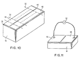
- the base body 14 in the form of a block or plate made of the interaction material, forms many acousto-optical devices that are grown and produced on the base body. Devices in the form of individual cells are obtained by cutting or cutting the block 14 in the areas between electrodes, thereby producing a cell shaped according to FIG.
- the acousto-optical device During operation, light enters the acousto-optical device through an optical window 38 of this device in the direction indicated by arrow 40.
- the acoustic waves generated by the transducer propagate downward, interact with the optical wave and bend it to produce a desired optical output signal.
- the electrodes do not cover the entire area of the surface 42 of the acousto-optical device or cell, the usable area of the base body made of interaction material is limited to the volume 24, which is indicated in FIG. 4 as a hatched area. As a result, there is an unnecessary waste of interaction material.
- the electrodes comprise two regions which are divided along a longitudinally extending separating space 44, so that a first electrode 46 and a second electrode 48 of an acousto-optical device are defined. Subsequent cutting or severing of the base body from the interaction material along dashed lines 50 results in an acousto-optical cell according to FIG. 11, which has the following advantages and properties.
- An electrical source 52 is connected between the first electrode 46 and the second electrode 48 to generate the vibrations in the thin transducer, which is arranged under the electrodes.
- the electrical energy passes through one Electrode and is capacitively transferred by the converter made of lithium niobate to the electrically conductive bonding layer arranged below.
- the tie layer in turn transfers the electrical energy through the transducer to the second electrode and then back to source 52.
- the acoustic energy generated in the transducer spreads out into the underlying base body from the interaction material and fills the entire volume of this body with acoustic waves.
- the optical waves enter in a direction perpendicular to the acoustic waves and are controlled and reshaped according to known principles.
Landscapes
- Physics & Mathematics (AREA)
- Nonlinear Science (AREA)
- General Physics & Mathematics (AREA)
- Optics & Photonics (AREA)
- Optical Modulation, Optical Deflection, Nonlinear Optics, Optical Demodulation, Optical Logic Elements (AREA)
- Optical Integrated Circuits (AREA)
Claims (4)
- Dispositif acousto-optique comportant un corps de base (14) réalisé en un matériau d'interaction pour le couplage d'ondes de pression acoustiques à des ondes optiques, et qui comporte une fenêtre optique pour l'injection d'une onde optique et une interface acoustique pour l'injection d'une onde acoustique dans le corps de base (14), et comportant une couche formant transducteur (36), qui est raccordée sur une certaine surface, par l'intermédiaire d'une couche intercalaire de liaison formée d'un matériau électriquement conducteur, à l'interface acoustique du corps de base (14), pour produire l'onde de pression acoustique injectée à travers la couche de liaison injectée dans le corps de base (14) à travers la couche de liaison, par application d'un signal électrique entre deux couches d'électrodes métalliques (46,48) séparées l'une de l'autre, caractérisé par le fait que les couches d'électrodes métalliques (46,48) sont déposées sur la couche formant transducteur (36) et recouvrent complètement cette dernière à l'exception d'un espace intercalaire en forme de fente.
- Dispositif suivant la revendication 1, caractérisé par le fait que la couche formant transducteur (36) contient du niobate de lithium.
- Dispositif suivant la revendication 1 ou 2, caractérisé par le fait que le matériau d'interaction du corps de base (14) contient du dioxyde de tellure.
- Procédé pour fabriquer un dispositif suivant l'une des revendications précédentes, caractérisé par le fait que sur une surface latérale d'un corps de base formé d'un matériau d'interaction pour le couplage d'ondes acoustiques de pression à des ondes optiques et possédant une longueur incluant un multiple d'une longueur prédéterminée du corps de base des dispositifs devant être fabriqués, on dépose une couche de liaison électriquement conductrice, on forme sur la couche de liaison une couche formant transducteur (36) et sur cette couche formant transducteur (36), on forme deux couches d'électrodes métalliques séparées par un espace intercalaire en forme de fente, qui s'étend sur toute la longueur du corps de départ, et qui recouvrent complètement la couche formant transducteur (36) à l'exception de l'espace intercalaire en forme de fente, et qu'on subdivise le corps fabriqué de cette manière à des intervalles qui correspondent à la longueur prédéterminée, perpendiculairement à la direction longitudinale de l'espace intercalaire en forme de fente.
Applications Claiming Priority (4)
| Application Number | Priority Date | Filing Date | Title |
|---|---|---|---|
| US63676684A | 1984-08-01 | 1984-08-01 | |
| US63664084A | 1984-08-01 | 1984-08-01 | |
| US636766 | 1984-08-01 | ||
| US636640 | 1984-08-01 |
Publications (3)
| Publication Number | Publication Date |
|---|---|
| EP0171012A2 EP0171012A2 (fr) | 1986-02-12 |
| EP0171012A3 EP0171012A3 (en) | 1987-08-26 |
| EP0171012B1 true EP0171012B1 (fr) | 1992-04-01 |
Family
ID=27092666
Family Applications (1)
| Application Number | Title | Priority Date | Filing Date |
|---|---|---|---|
| EP19850109518 Expired - Lifetime EP0171012B1 (fr) | 1984-08-01 | 1985-07-29 | Dispositif acousto-optique et méthode pour sa fabrication |
Country Status (2)
| Country | Link |
|---|---|
| EP (1) | EP0171012B1 (fr) |
| DE (1) | DE3585757D1 (fr) |
Families Citing this family (1)
| Publication number | Priority date | Publication date | Assignee | Title |
|---|---|---|---|---|
| US6236492B1 (en) * | 1999-08-03 | 2001-05-22 | Crystal Corporation | Electrode with a balanced centroid, soft edges and an apodization ratio greater than one |
Family Cites Families (6)
| Publication number | Priority date | Publication date | Assignee | Title |
|---|---|---|---|---|
| GB1192491A (en) * | 1968-03-15 | 1970-05-20 | Mullard Ltd | Apparatus for Treating a Light Beam |
| US3617931A (en) * | 1969-05-05 | 1971-11-02 | Bell Telephone Labor Inc | Acousto-optic devices using lead molybdate and related compounds |
| FR2088797A5 (fr) * | 1970-04-24 | 1972-01-07 | Thomson Csf | |
| US4052121A (en) * | 1975-09-10 | 1977-10-04 | Itek Corporation | Noncollinear tunable acousto-optic filter |
| US4336982A (en) * | 1980-08-04 | 1982-06-29 | Xerox Corporation | MgF2 Coating for promoting adherence of thin films to single crystal materials |
| DD159116A1 (de) * | 1981-05-20 | 1983-02-16 | Klaus Wunderlich | Akusto-optisches bauelement |
-
1985
- 1985-07-29 DE DE8585109518T patent/DE3585757D1/de not_active Expired - Lifetime
- 1985-07-29 EP EP19850109518 patent/EP0171012B1/fr not_active Expired - Lifetime
Also Published As
| Publication number | Publication date |
|---|---|
| EP0171012A2 (fr) | 1986-02-12 |
| EP0171012A3 (en) | 1987-08-26 |
| DE3585757D1 (de) | 1992-05-07 |
Similar Documents
| Publication | Publication Date | Title |
|---|---|---|
| DE2821791C2 (fr) | ||
| DE2418958A1 (de) | Wandlergitter fuer elastische oberflaechenwellen sowie akusto-optisches ablenkglied oder frequenzselektives uebertragungssystem mit einem solchen wandlergitter | |
| DE3201128C2 (de) | Optische Schaltvorrichtung | |
| DE2456560C3 (de) | Beugungsgitter mit veränderlicher Gitterkonstante | |
| DE68918372T2 (de) | Piezoelektrischer Wandler zur Volumenwellenerregung. | |
| DE2345088A1 (de) | Lineare wandleranordnung fuer die ultraschall-bildwandlung | |
| DE3587959T2 (de) | Akustischer Oberflächenwellen-Spektrumanalysator. | |
| DE2109904A1 (de) | Lichtablenker | |
| DE2529073C2 (de) | Koppelelement für Glasfaserlichtleiter | |
| DE3046903A1 (de) | Mit akustischen oberflaechenwellen arbeitende wandlervorrichtung fuer ein geraet zum aufzeichnen oder abspielen von information | |
| DE3912208A1 (de) | Optische aufzeichnungseinrichtung | |
| DE2758305C2 (de) | Verfahren und Vorrichtung zur Vermeidung von Zeilenstrukturen bei der Bildaufzeichnung | |
| DE2460218C2 (de) | Linearer Dateneingabewandler | |
| DE2256515C2 (de) | Holographisches System zur Bildung eines Indexnetzes im Volumen eines kristallinen Plättchens | |
| DE2166342C3 (de) | Akustisch-optisches Filter | |
| DE2542854A1 (de) | Akustisches oberflaechenwellenfilter | |
| DE3138745A1 (de) | Akustooptischer lichtablenker mit hoher aufloesung | |
| DE4327638A1 (de) | Vorrichtung zur Geschwindigkeitsanpassung zwischen elektrischen und optischen Signalen | |
| DE69230886T2 (de) | Vorrichtung mit optischem gitter | |
| DE2006475A1 (de) | Vorrichtung zum Ablenken eines einfallenden Licnttaünciels in eine von zwei divergierenden Richtungen | |
| DE2159900A1 (de) | Akustische Lichtablenkeinrichtung | |
| DE2220148C2 (de) | Optische Steuervorrichtung mit einem Dünnschichtwellenleiter und einer akustischen Welle | |
| EP0171012B1 (fr) | Dispositif acousto-optique et méthode pour sa fabrication | |
| EP0915353A2 (fr) | Arrangement de guides d'ondes optiques | |
| DE2359556A1 (de) | Verfahren zur steuerbaren richtungsablenkung von lichtstrahlen |
Legal Events
| Date | Code | Title | Description |
|---|---|---|---|
| PUAI | Public reference made under article 153(3) epc to a published international application that has entered the european phase |
Free format text: ORIGINAL CODE: 0009012 |
|
| AK | Designated contracting states |
Designated state(s): DE FR GB NL SE |
|
| RIN1 | Information on inventor provided before grant (corrected) |
Inventor name: SCHEFF, VICTOR Inventor name: AMANO, MASAHARU Inventor name: ROOS, EDWARD V. |
|
| PUAL | Search report despatched |
Free format text: ORIGINAL CODE: 0009013 |
|
| AK | Designated contracting states |
Kind code of ref document: A3 Designated state(s): DE FR GB NL SE |
|
| 17P | Request for examination filed |
Effective date: 19880215 |
|
| 17Q | First examination report despatched |
Effective date: 19900322 |
|
| GRAA | (expected) grant |
Free format text: ORIGINAL CODE: 0009210 |
|
| AK | Designated contracting states |
Kind code of ref document: B1 Designated state(s): DE FR GB NL SE |
|
| REF | Corresponds to: |
Ref document number: 3585757 Country of ref document: DE Date of ref document: 19920507 |
|
| ET | Fr: translation filed | ||
| PGFP | Annual fee paid to national office [announced via postgrant information from national office to epo] |
Ref country code: GB Payment date: 19920619 Year of fee payment: 8 |
|
| GBT | Gb: translation of ep patent filed (gb section 77(6)(a)/1977) | ||
| PGFP | Annual fee paid to national office [announced via postgrant information from national office to epo] |
Ref country code: FR Payment date: 19920724 Year of fee payment: 8 |
|
| PGFP | Annual fee paid to national office [announced via postgrant information from national office to epo] |
Ref country code: SE Payment date: 19920728 Year of fee payment: 8 |
|
| PGFP | Annual fee paid to national office [announced via postgrant information from national office to epo] |
Ref country code: NL Payment date: 19920731 Year of fee payment: 8 |
|
| PLBE | No opposition filed within time limit |
Free format text: ORIGINAL CODE: 0009261 |
|
| STAA | Information on the status of an ep patent application or granted ep patent |
Free format text: STATUS: NO OPPOSITION FILED WITHIN TIME LIMIT |
|
| 26N | No opposition filed | ||
| PG25 | Lapsed in a contracting state [announced via postgrant information from national office to epo] |
Ref country code: DE Effective date: 19930401 |
|
| PG25 | Lapsed in a contracting state [announced via postgrant information from national office to epo] |
Ref country code: GB Effective date: 19930729 |
|
| PG25 | Lapsed in a contracting state [announced via postgrant information from national office to epo] |
Ref country code: SE Effective date: 19930730 |
|
| PG25 | Lapsed in a contracting state [announced via postgrant information from national office to epo] |
Ref country code: NL Effective date: 19940201 |
|
| NLV4 | Nl: lapsed or anulled due to non-payment of the annual fee | ||
| GBPC | Gb: european patent ceased through non-payment of renewal fee |
Effective date: 19930729 |
|
| PG25 | Lapsed in a contracting state [announced via postgrant information from national office to epo] |
Ref country code: FR Effective date: 19940331 |
|
| REG | Reference to a national code |
Ref country code: FR Ref legal event code: ST |
|
| EUG | Se: european patent has lapsed |
Ref document number: 85109518.2 Effective date: 19940210 |