EP0171269A2 - Dispositif de réflexion de la lumière - Google Patents
Dispositif de réflexion de la lumière Download PDFInfo
- Publication number
- EP0171269A2 EP0171269A2 EP85305511A EP85305511A EP0171269A2 EP 0171269 A2 EP0171269 A2 EP 0171269A2 EP 85305511 A EP85305511 A EP 85305511A EP 85305511 A EP85305511 A EP 85305511A EP 0171269 A2 EP0171269 A2 EP 0171269A2
- Authority
- EP
- European Patent Office
- Prior art keywords
- plug
- light reflecting
- reflector
- hole
- barbs
- Prior art date
- Legal status (The legal status is an assumption and is not a legal conclusion. Google has not performed a legal analysis and makes no representation as to the accuracy of the status listed.)
- Withdrawn
Links
Images
Classifications
-
- F—MECHANICAL ENGINEERING; LIGHTING; HEATING; WEAPONS; BLASTING
- F16—ENGINEERING ELEMENTS AND UNITS; GENERAL MEASURES FOR PRODUCING AND MAINTAINING EFFECTIVE FUNCTIONING OF MACHINES OR INSTALLATIONS; THERMAL INSULATION IN GENERAL
- F16B—DEVICES FOR FASTENING OR SECURING CONSTRUCTIONAL ELEMENTS OR MACHINE PARTS TOGETHER, e.g. NAILS, BOLTS, CIRCLIPS, CLAMPS, CLIPS OR WEDGES; JOINTS OR JOINTING
- F16B21/00—Means for preventing relative axial movement of a pin, spigot, shaft or the like and a member surrounding it; Stud-and-socket releasable fastenings
- F16B21/06—Releasable fastening devices with snap-action
- F16B21/08—Releasable fastening devices with snap-action in which the stud, pin, or spigot has a resilient part
- F16B21/088—Releasable fastening devices with snap-action in which the stud, pin, or spigot has a resilient part the stud, pin or spigot being integrally formed with the component to be fastened, e.g. forming part of the sheet, plate or strip
-
- E—FIXED CONSTRUCTIONS
- E01—CONSTRUCTION OF ROADS, RAILWAYS, OR BRIDGES
- E01F—ADDITIONAL WORK, SUCH AS EQUIPPING ROADS OR THE CONSTRUCTION OF PLATFORMS, HELICOPTER LANDING STAGES, SIGNS, SNOW FENCES, OR THE LIKE
- E01F9/00—Arrangement of road signs or traffic signals; Arrangements for enforcing caution
- E01F9/60—Upright bodies, e.g. marker posts or bollards; Supports for road signs
- E01F9/658—Upright bodies, e.g. marker posts or bollards; Supports for road signs characterised by means for fixing
- E01F9/669—Upright bodies, e.g. marker posts or bollards; Supports for road signs characterised by means for fixing for fastening to safety barriers or the like
-
- F—MECHANICAL ENGINEERING; LIGHTING; HEATING; WEAPONS; BLASTING
- F16—ENGINEERING ELEMENTS AND UNITS; GENERAL MEASURES FOR PRODUCING AND MAINTAINING EFFECTIVE FUNCTIONING OF MACHINES OR INSTALLATIONS; THERMAL INSULATION IN GENERAL
- F16B—DEVICES FOR FASTENING OR SECURING CONSTRUCTIONAL ELEMENTS OR MACHINE PARTS TOGETHER, e.g. NAILS, BOLTS, CIRCLIPS, CLAMPS, CLIPS OR WEDGES; JOINTS OR JOINTING
- F16B13/00—Dowels or other devices fastened in walls or the like by inserting them in holes made therein for that purpose
- F16B13/02—Dowels or other devices fastened in walls or the like by inserting them in holes made therein for that purpose in one piece with protrusions or ridges on the shaft
Definitions
- the present invention relates to light reflecting devices.
- the present invention seeks to provide a reflecting device which may be used for the purpose of warning or guiding vehicular traffic and which can be readily mounted in position.
- the present invention provides a light reflecting device comprising a body having light reflecting means thereon, and retaining means adapted for retentive engagement with an opening therefor in a suitable structure such as brickwork, woodwork or the like whereby said light reflecting means is presented for light reflecting action.
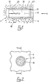
- the plug 2 is preferably of suitable plastics material and is in the nature of a wall plug for fixing purposes in that it is adapted to be driven for a retentive engagement or fit in a hole 3 therefor in brickwork 4, woodwork or other structure (including in some cases metal structure).
- the plug 2 is shown provided on its exterior with barbs 23 whilst the rear part of the plug may be split longitudinally as at 22 i.e. at one or more places about its circumference for radial contraction with a resilient yielding action whereby the barbs 23 of the plug 2 are radially thrust into firm retentive engagement with the wall 30 of the hole 3.
- the barbs may be arcuate or extend around the full circumference of the plug 2.
- the diameter of the plug 2 may be varied to provide a reflective area of the reflector disc 1 of preselected size, and may be of the order of 2.5 cm in diameter or thereabouts i.e. so that the hole 3 can still be produced by, for example, a masonry drill of a size which is readily available.
- the outer end 21 also serves to protect the reflector 1 against damage, and to some degree against the accumulation of dirt and rain, whilst any accumulated dirt on the face of the reflector 1 can be easily removed.
- the plug 2 is shown of generally uniform diameter throughout its length but may be tapered outwardly towards its inner end to provide for suitable compression of the plug 2 for retentive engagement in the hole. If necessary the inner end portion of the plug bore 20 may receive an expander (not shown) which abuts the inner end of the hole 3 as the plug 2 is driven into position, the expander being dimensioned to cause the plug to expand as the expander is forced into the plug.
- the expander is conveniently tapered inwardly towards the plug outer end.
- the reflector disc 1 is located in an annular groove 221 in the plug bore 22 e.g. with a snap fit or may be moulded into the plug 2. While shown recessed from the outer end of the plug the disc 1 may of course be positioned at the outer end.
- the reflective face 10 is preferably of the retro-reflective type providing myriad prismatic points (i.e. many thousand per square centimetre) such as the reflective material known under the Registered Trade Mark "Reflexite".
- the reflector plugs 2 can be fitted in positions of use e.g. in a wall, post or other structure especially for reflecting the light of vehicle headlamps or of other vehicle lamps such as reversing lamps for guidance when reversing a vehicle up to a loading/unloading platform.
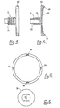
- FIGS 3 to 5 of the drawings show a further embodiment of the invention in which, although more vulnerable to damage, the plug 2 may be provided with an enlarged head 60 (preferably generally planar in shape) receiving a reflector 62 of corresponding size, such as by snap engagement with locating slots and lugs 64, 66, the head abutting the exterior of the brickwork when the plug 2 is fully driven into the hole.
- a reflector 62 preferably generally planar in shape
- the head 60 is shown integral with the plug 2 it may of course be detachable.
- the plug bore may be dimensioned to receive a screw which serves to expand the plug as the screw is screwed into the plug.
- the screw may extend through the head to secure the latter or may be inserted on temporary removal of the head.
- the head may, of course, be of any suitable shape.
- the surface of the head 60 receiving the reflector, and the reflector is of concave shape, although any preferred curvature may be used.
- a retaining washer 70 which has two radially inwardly projecting lugs 72 to engage the barbs 23.
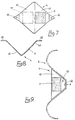
- the support member of the reflector device is shown consisting of a plate 4 of sheet metal angled to provide two faces 40, 41 at least one of which receives a reflector or reflective material 11.
- the reflector is shown proud of the face 40, the latter may be provided with a recess in which the reflector is received conveniently flush with the surface 40.
- Each face 40, 41 has mutually inclined sides 42 converging to a mounting lug 45 and the arrangement is such that the angled plate is adapted to have a locating engagement with the longitudinal recess 50 of a steel crash barrier 5 which is usually provided along the central reservation of a motorway or in other locations
- the plate 4 is readily secured by the lugs 45 to the recessed part 50 of the barrier 5 by screws, rivets 6 or other suitable fixing devices, or by welding e.g. spot welding.
- each reflector at 11 faces the headlamps of oncoming traffic along an adjacent carriageway where the traffic observes the lefthand rule of the road. Particularly in fog or other conditions of poor visability the reflectors 11 provide guidance to drivers of motor vehicles on the carriageway and are at a level closely adjacent to that of the headlamps for optimum reflection.
- the other face 41 of the angled plate 4 is not seen by vehicle drivers on either carriageway but may nevertheless be provided with reflective material as indicated at 11' i.e. for use when contra-flow operation of traffic on the motorway is in force.
- the entire or substantially the entire outer surface of the angled plate 4 may be faced or coated with reflective material whilst instead of a plate a cast or moulded mounting member e.g. of durable plastics material may be employed of a similar shape for locating engagement and attachment in the barrier recess 50 and to provide the reflector bearing face 40 or faces 40, 41.
- a cast or moulded mounting member e.g. of durable plastics material may be employed of a similar shape for locating engagement and attachment in the barrier recess 50 and to provide the reflector bearing face 40 or faces 40, 41.
- the reflective material 11 is preferably of the retro-reflective type already referred to above.
Landscapes
- Engineering & Computer Science (AREA)
- General Engineering & Computer Science (AREA)
- Mechanical Engineering (AREA)
- Architecture (AREA)
- Civil Engineering (AREA)
- Structural Engineering (AREA)
- Non-Portable Lighting Devices Or Systems Thereof (AREA)
- Road Signs Or Road Markings (AREA)
Applications Claiming Priority (2)
| Application Number | Priority Date | Filing Date | Title |
|---|---|---|---|
| GB8419760 | 1984-08-02 | ||
| GB848419760A GB8419760D0 (en) | 1984-08-02 | 1984-08-02 | Reflector devices |
Publications (2)
| Publication Number | Publication Date |
|---|---|
| EP0171269A2 true EP0171269A2 (fr) | 1986-02-12 |
| EP0171269A3 EP0171269A3 (fr) | 1987-07-15 |
Family
ID=10564861
Family Applications (1)
| Application Number | Title | Priority Date | Filing Date |
|---|---|---|---|
| EP85305511A Withdrawn EP0171269A3 (fr) | 1984-08-02 | 1985-08-02 | Dispositif de réflexion de la lumière |
Country Status (2)
| Country | Link |
|---|---|
| EP (1) | EP0171269A3 (fr) |
| GB (1) | GB8419760D0 (fr) |
Cited By (3)
| Publication number | Priority date | Publication date | Assignee | Title |
|---|---|---|---|---|
| FR2607841A1 (fr) * | 1986-12-09 | 1988-06-10 | Profilafroid Sa | Glissiere de securite routiere |
| EP0509788A1 (fr) * | 1991-04-15 | 1992-10-21 | Allan Jarvis | Dispositif de signalisation routière et système de sécurité de la route |
| EP0658654A1 (fr) * | 1993-12-15 | 1995-06-21 | Kurt Alten | Bande d'avertissement pour rampe de chargement et dispositifs de chargement auxiliaire |
Family Cites Families (6)
| Publication number | Priority date | Publication date | Assignee | Title |
|---|---|---|---|---|
| DE1700489U (de) * | 1952-05-26 | 1955-06-16 | Vorwerk & Sohn | Rueckstrahler, insbesondere fuer fahrzeuge. |
| DE1750455U (de) * | 1957-03-27 | 1957-08-14 | Karl Haybach | Reflektor an strassenleitplanken. |
| DE1798139A1 (de) * | 1968-08-29 | 1971-11-04 | Telefunken Patent | Vorrichtung zum Polieren von Proben |
| DE7822905U1 (de) * | 1978-07-31 | 1978-11-09 | G. Goseberg & Co Gmbh, 5990 Altena | Strassenmarkierungsnagel |
| DE7832819U1 (de) * | 1978-11-04 | 1979-08-23 | Wegert, Hans, 7024 Filderstadt | Optischer signalkoerper fuer eine am fahrbahnrand eines nur in einer richtung zu befahrenden strassenabschnitts angeordnete warnvorrichtung |
| US4221498A (en) * | 1979-05-07 | 1980-09-09 | Astro Optics Corporation | Roadside barrier reflector |
-
1984
- 1984-08-02 GB GB848419760A patent/GB8419760D0/en active Pending
-
1985
- 1985-08-02 EP EP85305511A patent/EP0171269A3/fr not_active Withdrawn
Cited By (4)
| Publication number | Priority date | Publication date | Assignee | Title |
|---|---|---|---|---|
| FR2607841A1 (fr) * | 1986-12-09 | 1988-06-10 | Profilafroid Sa | Glissiere de securite routiere |
| BE1004351A3 (fr) * | 1986-12-09 | 1992-11-10 | Profilafroid Sa | Glissiere de securite routiere. |
| EP0509788A1 (fr) * | 1991-04-15 | 1992-10-21 | Allan Jarvis | Dispositif de signalisation routière et système de sécurité de la route |
| EP0658654A1 (fr) * | 1993-12-15 | 1995-06-21 | Kurt Alten | Bande d'avertissement pour rampe de chargement et dispositifs de chargement auxiliaire |
Also Published As
| Publication number | Publication date |
|---|---|
| EP0171269A3 (fr) | 1987-07-15 |
| GB8419760D0 (en) | 1984-09-05 |
Similar Documents
| Publication | Publication Date | Title |
|---|---|---|
| US4729690A (en) | Self-righting highway marker support and method for installing same | |
| US3587416A (en) | Pavement marker and mounting base member | |
| US4224002A (en) | Highway delineator | |
| JPH11140832A (ja) | 道路標識柱 | |
| KR102077973B1 (ko) | 중앙분리대 방현망용 델리네이터 | |
| US20010028824A1 (en) | Reduced impact load snowplowable pavement marker | |
| US4848958A (en) | Recessed deflecting road reflector | |
| GB2162566A (en) | Light reflecting devices suitable for use in road safety | |
| US4395155A (en) | Reflective highway marker | |
| US20050008434A1 (en) | Roadway projecting marker | |
| GB2093892A (en) | Road marker post | |
| RU8977U1 (ru) | Дорожный световозвращающий знак | |
| US20110164922A1 (en) | Roadway marker and reflector guard | |
| KR200330045Y1 (ko) | 차선표지장치 | |
| KR200191507Y1 (ko) | 차선표시용 도로표지병 | |
| KR200491926Y1 (ko) | 도로 경계석 또는 옹벽의 반사판 설치구조 | |
| KR200268756Y1 (ko) | 반사판이부착된도로난간지주 | |
| JP3724880B2 (ja) | 凍結表示付スノーポール | |
| KR200287773Y1 (ko) | 도로경계용 차량안내구 | |
| KR200234498Y1 (ko) | 도로 차선 표지병 | |
| KR200354790Y1 (ko) | 차량진입 방지대 | |
| KR200347846Y1 (ko) | 형광반사판체가 부착된 가이드레일의 조립장치 | |
| JP2002363927A (ja) | 広角視線誘導標 | |
| KR200184733Y1 (ko) | 재활용 도로 표지병 | |
| KR100520307B1 (ko) | 차선표지장치 |
Legal Events
| Date | Code | Title | Description |
|---|---|---|---|
| PUAI | Public reference made under article 153(3) epc to a published international application that has entered the european phase |
Free format text: ORIGINAL CODE: 0009012 |
|
| AK | Designated contracting states |
Designated state(s): AT BE CH DE FR IT LI LU NL SE |
|
| PUAL | Search report despatched |
Free format text: ORIGINAL CODE: 0009013 |
|
| AK | Designated contracting states |
Kind code of ref document: A3 Designated state(s): AT BE CH DE FR IT LI LU NL SE |
|
| STAA | Information on the status of an ep patent application or granted ep patent |
Free format text: STATUS: THE APPLICATION IS DEEMED TO BE WITHDRAWN |
|
| 18D | Application deemed to be withdrawn |
Effective date: 19880116 |