EP0171485A2 - Eléments pour joindre des pièces de formes différentes sous des angles divers - Google Patents
Eléments pour joindre des pièces de formes différentes sous des angles divers Download PDFInfo
- Publication number
- EP0171485A2 EP0171485A2 EP84830110A EP84830110A EP0171485A2 EP 0171485 A2 EP0171485 A2 EP 0171485A2 EP 84830110 A EP84830110 A EP 84830110A EP 84830110 A EP84830110 A EP 84830110A EP 0171485 A2 EP0171485 A2 EP 0171485A2
- Authority
- EP
- European Patent Office
- Prior art keywords
- bodies
- elements
- parts
- site
- joint
- Prior art date
- Legal status (The legal status is an assumption and is not a legal conclusion. Google has not performed a legal analysis and makes no representation as to the accuracy of the status listed.)
- Withdrawn
Links
Images

Classifications
-
- E—FIXED CONSTRUCTIONS
- E04—BUILDING
- E04G—SCAFFOLDING; FORMS; SHUTTERING; BUILDING IMPLEMENTS OR AIDS, OR THEIR USE; HANDLING BUILDING MATERIALS ON THE SITE; REPAIRING, BREAKING-UP OR OTHER WORK ON EXISTING BUILDINGS
- E04G7/00—Connections between parts of the scaffold
- E04G7/02—Connections between parts of the scaffold with separate coupling elements
- E04G7/06—Stiff scaffolding clamps for connecting scaffold members of common shape
- E04G7/12—Clamps or clips for crossing members
- E04G7/14—Clamps or clips for crossing members for clamping the members independently
-
- E—FIXED CONSTRUCTIONS
- E04—BUILDING
- E04G—SCAFFOLDING; FORMS; SHUTTERING; BUILDING IMPLEMENTS OR AIDS, OR THEIR USE; HANDLING BUILDING MATERIALS ON THE SITE; REPAIRING, BREAKING-UP OR OTHER WORK ON EXISTING BUILDINGS
- E04G7/00—Connections between parts of the scaffold
- E04G7/02—Connections between parts of the scaffold with separate coupling elements
- E04G7/06—Stiff scaffolding clamps for connecting scaffold members of common shape
- E04G7/12—Clamps or clips for crossing members
- E04G7/14—Clamps or clips for crossing members for clamping the members independently
- E04G7/16—Clamps or clips for crossing members for clamping the members independently of which the clamping parts for the different members are rotatable with respect to one another
-
- E—FIXED CONSTRUCTIONS
- E04—BUILDING
- E04G—SCAFFOLDING; FORMS; SHUTTERING; BUILDING IMPLEMENTS OR AIDS, OR THEIR USE; HANDLING BUILDING MATERIALS ON THE SITE; REPAIRING, BREAKING-UP OR OTHER WORK ON EXISTING BUILDINGS
- E04G7/00—Connections between parts of the scaffold
- E04G7/02—Connections between parts of the scaffold with separate coupling elements
- E04G7/06—Stiff scaffolding clamps for connecting scaffold members of common shape
- E04G7/12—Clamps or clips for crossing members
- E04G7/18—Clamps or clips for crossing members for clamping the members against one another or against a separate cushioning piece between them
-
- F—MECHANICAL ENGINEERING; LIGHTING; HEATING; WEAPONS; BLASTING
- F16—ENGINEERING ELEMENTS AND UNITS; GENERAL MEASURES FOR PRODUCING AND MAINTAINING EFFECTIVE FUNCTIONING OF MACHINES OR INSTALLATIONS; THERMAL INSULATION IN GENERAL
- F16B—DEVICES FOR FASTENING OR SECURING CONSTRUCTIONAL ELEMENTS OR MACHINE PARTS TOGETHER, e.g. NAILS, BOLTS, CIRCLIPS, CLAMPS, CLIPS OR WEDGES; JOINTS OR JOINTING
- F16B2/00—Friction-grip releasable fastenings
- F16B2/02—Clamps, i.e. with gripping action effected by positive means other than the inherent resistance to deformation of the material of the fastening
- F16B2/06—Clamps, i.e. with gripping action effected by positive means other than the inherent resistance to deformation of the material of the fastening external, i.e. with contracting action
- F16B2/12—Clamps, i.e. with gripping action effected by positive means other than the inherent resistance to deformation of the material of the fastening external, i.e. with contracting action using sliding jaws
-
- F—MECHANICAL ENGINEERING; LIGHTING; HEATING; WEAPONS; BLASTING
- F16—ENGINEERING ELEMENTS AND UNITS; GENERAL MEASURES FOR PRODUCING AND MAINTAINING EFFECTIVE FUNCTIONING OF MACHINES OR INSTALLATIONS; THERMAL INSULATION IN GENERAL
- F16B—DEVICES FOR FASTENING OR SECURING CONSTRUCTIONAL ELEMENTS OR MACHINE PARTS TOGETHER, e.g. NAILS, BOLTS, CIRCLIPS, CLAMPS, CLIPS OR WEDGES; JOINTS OR JOINTING
- F16B7/00—Connections of rods or tubes, e.g. of non-circular section, mutually, including resilient connections
- F16B7/04—Clamping or clipping connections
-
- F—MECHANICAL ENGINEERING; LIGHTING; HEATING; WEAPONS; BLASTING
- F16—ENGINEERING ELEMENTS AND UNITS; GENERAL MEASURES FOR PRODUCING AND MAINTAINING EFFECTIVE FUNCTIONING OF MACHINES OR INSTALLATIONS; THERMAL INSULATION IN GENERAL
- F16B—DEVICES FOR FASTENING OR SECURING CONSTRUCTIONAL ELEMENTS OR MACHINE PARTS TOGETHER, e.g. NAILS, BOLTS, CIRCLIPS, CLAMPS, CLIPS OR WEDGES; JOINTS OR JOINTING
- F16B7/00—Connections of rods or tubes, e.g. of non-circular section, mutually, including resilient connections
- F16B7/04—Clamping or clipping connections
- F16B7/044—Clamping or clipping connections for rods or tubes being in angled relationship
- F16B7/048—Clamping or clipping connections for rods or tubes being in angled relationship for rods or for tubes without using the innerside thereof
- F16B7/0493—Clamping or clipping connections for rods or tubes being in angled relationship for rods or for tubes without using the innerside thereof forming a crossed-over connection
Definitions
- the present invention refers to a group of elements for the realization of metallic or other joints for connecting and fixing of two or more variously oriented and orientable sections, whether tables, panels, axes, laths, tubes or the like, which in this discussion will be called "sections" for simplicity, achieving a system with great applicative versatility and variability of combinations of different elements able to realize tightening junction for two, three or more sections oriented in any direction and of any type.
- the aim of the present invention is to realize a group of elements which can be variously paired and combined to form connecting joints suitable for any requirement and which can overcome the inconveniences cited above, through the realization between two bodies in pressure contact of a single axial joint organ, orthogonal to the directions of orientation of each pair of connected sections.
- Another aim of the invention is to realize a joint organ which can allow orientation of the bodies in pressure contact at any angle or at a predetermined number of rigid angles; another is to realize a joint organ which allows coupling of contact bodies with different pairing sections (for example, tubes andsouare laths, or tables with panels, etc.).
- different pairing sections for example, tubes andsouare laths, or tables with panels, etc.
- Another aim is to realize joint with a simple structure, easily and rapidly assembled and disassembled, with a single joint organ, in a simple maneuver, for each pair of connections.
- Another aim is to realize a type of three directional joint which can be reduced to bidimensional when necessary, by simply removing (or not assembling) the superfluous and space-taking or prehensile part.
- the object of the invention which, in terms of the group of elements for the realization of connecting joints according to the invention as well as from a general point of view, is characterized by comprising at least two counterposed bodies bearing on at least one surface acoupling section with a flat, prismatic or cylindrical shape corresponding to the shape of the external surface of the section to be joined, equipped solidly with a fixing and reciprocal joint organ, arranged laterally or in correspondence with one end, developing axially and orthogonally to the direction of the sections to be joined, said organ comprising two reciprocally and mutually fixable and tightenable parts, each joined to one of said bodies, and one of said parts realizing internally and longitudinally a site fixing in a sliding fashion a complementary expansion joined to the other of the two Darts of the joint organ, axially internally in turn containing a threaded cavity fixing the equally t.readed end of a bolt held freely rotating in said site and connected to its head; said bolt, on screwing in said cavity, supplies the axial sliding contrary to
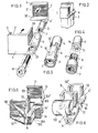
- figure 1 shows a joint according to the invention comprising two opposite bodies 1 and 1' with similar coupling surfaces 2 and 2' shaped according to flat sections and equipped with pairs of transverse slats 3 and 30 in correspondence with the two otter edges.
- said bodies 1 and 1' are particularly suited for pairing two sections of laths with a quandran- gular section, and are laterally provided with two parts 4 and 4' joined to them to complementarily realize a fixing and joining organ.
- Said part 4 of said organ has internally and longitudinally a site 5 fixing internally in a sliding fashion a complementary expansion 6, presented by the other part 4', axially in turn with a threaded cavity 7.
- a common bolt 8 fits freely rotating and axially sliding in said site 5 and is fixed by its complementary thteading in said cavity 7.
- the screwing of bolt 8 into cavity 7 causes the sliding insertion of expansion 6 in site 5 and so the approach of the two opposite bodies 1 arid 1', or rather the tightening of the sections or laths paired between them.
- the maximum limit of the reciprocal locking of the two parts 4 and 4' may be defined by a peripheral rise 9 delimiting said expansion 6 and coming against the corresponding end of said site 5.
- both said site 5 and expansion 6 are complementarily cylindrical, and so said expansion is xially sliding and freely rotating in site 5.
- This conformation allows a continuous range of reciprocal angles between the two bodies 1 and 1', before they are tightened, and so allows the joining of sections at any angle, from the orthogonal one in figure 1 to the parallel one in figure 2.
- Figure 3 shows a realization of the corresponding ends of said parts 4 and 4' of the joint organ, which are peripherally and circularly equipped with complementary toothing 10 and 10' so as to define, when reciprocally fixed, in the final phase of tlghtening the two parts, a pre-established number of rigid angles of the two opposite bodies 1 and 1'.
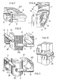
- Figure 4 shows a realization similar to the preceding one, in which both said site 5 and said expansion 6 are complementary and substantially cylindrical, and said expansion has on its surface multiple axial edges 11 which are regularly circumferential and can be fixed in complementary grooves 11' on the inner surface of site 5. Both these realizations allow the reciprocal angles between bodies 1 and 1' to be held to a pre-established number, allowing for said angles a rigid association of said two bodies.
- Figure 5 shows another example of the joint in figure 2 where the two bodies 101 and 101', with a pairing section of a different conformation that that of the previously described 1 and 1', are equipped on the surfaces opposite those involved in the joint with supporting and stiffening ribs 13 for support of the respective parts 104 and 104' of the joint organ.
- said parts are shaped according to another realization in which said site 105 and said expansion 106 have complementary quadrangular, or more generally - polygonal, sections, defining corresponding respective fixing angle and reciprocal sliding.
- all the coupling surfaces of the various bodies forming the various types of joints described may be equipped with rivets or ribbing or edging (not shown in the tables for the sake of simplicity) developed longitudinally or transversely, to increase and improve the adhesion and holding capacity of the bodies themseives on the surfaces of the section to be joined.
Landscapes
- Engineering & Computer Science (AREA)
- Architecture (AREA)
- Mechanical Engineering (AREA)
- General Engineering & Computer Science (AREA)
- Civil Engineering (AREA)
- Structural Engineering (AREA)
- Mutual Connection Of Rods And Tubes (AREA)
- Prostheses (AREA)
Applications Claiming Priority (4)
| Application Number | Priority Date | Filing Date | Title |
|---|---|---|---|
| IT4815183 | 1983-04-22 | ||
| IT8348151A IT1212862B (it) | 1983-04-22 | 1983-04-22 | Giunti con raccordo ad asse scorrevole, per scaffalature e/o impalcature ad aste quadrate oppure rotonde |
| IT4767884 | 1984-02-10 | ||
| IT47678/84A IT1199061B (it) | 1984-02-10 | 1984-02-10 | Giunti con raccordo ad asse per qualsivoglia costruzione |
Publications (2)
| Publication Number | Publication Date |
|---|---|
| EP0171485A2 true EP0171485A2 (fr) | 1986-02-19 |
| EP0171485A3 EP0171485A3 (fr) | 1988-03-02 |
Family
ID=26329219
Family Applications (1)
| Application Number | Title | Priority Date | Filing Date |
|---|---|---|---|
| EP84830110A Withdrawn EP0171485A3 (fr) | 1983-04-22 | 1984-04-11 | Eléments pour joindre des pièces de formes différentes sous des angles divers |
Country Status (4)
| Country | Link |
|---|---|
| EP (1) | EP0171485A3 (fr) |
| AU (1) | AU2712184A (fr) |
| ES (1) | ES287841Y (fr) |
| GR (1) | GR81955B (fr) |
Cited By (7)
| Publication number | Priority date | Publication date | Assignee | Title |
|---|---|---|---|---|
| GB2205142A (en) * | 1987-05-29 | 1988-11-30 | Home Doors | Connector assembly |
| FR2628330A1 (fr) * | 1988-03-10 | 1989-09-15 | Barde Yvon | Element de prise amovible d'escalade a fixation perfectionnee |
| WO1989011813A1 (fr) * | 1988-05-31 | 1989-12-14 | KÖNIG-HAUG, Beatrice | Systeme de rayonnage |
| GB2243629A (en) * | 1990-05-04 | 1991-11-06 | Michael Christopher Lawlor | A jointing bracket |
| FR2714931A1 (fr) * | 1994-01-10 | 1995-07-13 | Antunes Eduardo | Dispositif de sécurité assurant la stabilité des échelles par fixation aux gardecorps. |
| WO1997003273A1 (fr) * | 1995-07-12 | 1997-01-30 | Eduardo Antunes | Dispositif de securite assurant la stabilite des echelles par fixation intermediaire de l'echelle aux structures tubulaires ou rectangulaires d'echafaudages ou garde-corps quelle que soit leur inclinaison |
| HRP20070313B1 (en) * | 2007-07-13 | 2012-03-31 | Stanišić Nikša | Four-angled joint |
Families Citing this family (6)
| Publication number | Priority date | Publication date | Assignee | Title |
|---|---|---|---|---|
| BG45333A1 (fr) * | 1986-02-14 | 1989-05-15 | Georgi B Pantev | |
| AU596917B2 (en) * | 1987-11-02 | 1990-05-17 | Tubemakers Of Australia Limited | An adjustable coupling |
| WO1991004422A1 (fr) * | 1989-09-21 | 1991-04-04 | Showers Corporation Pty Ltd | Raccords a usage flexible, en particulier pour structures de jeux de construction |
| AU626221B2 (en) * | 1989-09-21 | 1992-07-23 | Rubbermaid Australia Pty Ltd | Flexible use connectors, especially for play structures |
| AU631701B2 (en) * | 1989-12-07 | 1992-12-03 | Neil Scott Head | Clamping device, carrier rail and elongate member assembly, and screen |
| CN111694405B (zh) * | 2020-06-16 | 2023-05-16 | 重庆电子工程职业学院 | 一种基于ic控制的远程通讯系统 |
Family Cites Families (4)
| Publication number | Priority date | Publication date | Assignee | Title |
|---|---|---|---|---|
| DE2308093C3 (de) * | 1973-02-19 | 1976-01-08 | Bremshey Ag, 5650 Solingen | Klemmbeschlag |
| CH558890A (de) * | 1973-06-26 | 1975-02-14 | Glatz Ag | Vorrichtung zum verstellbaren verbinden von mindestens zwei konstruktionselementen, insbesondere fuer rohre oder staebe. |
| IT1028693B (it) * | 1975-01-13 | 1979-02-10 | Sian Spa | Giunto per il rapido collegamento di elementi profilati di strutture composite quali scaffalature pareti divisorie chioschi e simili |
| FR2479921A1 (fr) * | 1980-04-04 | 1981-10-09 | Giraudet Bernard | Raccord pour l'assemblage a quatre-vingt-dix degres notamment d'organes tubulaires de section ronde |
-
1984
- 1984-04-11 EP EP84830110A patent/EP0171485A3/fr not_active Withdrawn
- 1984-04-18 GR GR74467A patent/GR81955B/el unknown
- 1984-04-18 ES ES1984287841U patent/ES287841Y/es not_active Expired
- 1984-04-19 AU AU27121/84A patent/AU2712184A/en not_active Abandoned
Cited By (8)
| Publication number | Priority date | Publication date | Assignee | Title |
|---|---|---|---|---|
| GB2205142A (en) * | 1987-05-29 | 1988-11-30 | Home Doors | Connector assembly |
| FR2628330A1 (fr) * | 1988-03-10 | 1989-09-15 | Barde Yvon | Element de prise amovible d'escalade a fixation perfectionnee |
| WO1989011813A1 (fr) * | 1988-05-31 | 1989-12-14 | KÖNIG-HAUG, Beatrice | Systeme de rayonnage |
| GB2243629A (en) * | 1990-05-04 | 1991-11-06 | Michael Christopher Lawlor | A jointing bracket |
| GB2243629B (en) * | 1990-05-04 | 1994-07-13 | Michael Christopher Lawlor | A jointing bracket |
| FR2714931A1 (fr) * | 1994-01-10 | 1995-07-13 | Antunes Eduardo | Dispositif de sécurité assurant la stabilité des échelles par fixation aux gardecorps. |
| WO1997003273A1 (fr) * | 1995-07-12 | 1997-01-30 | Eduardo Antunes | Dispositif de securite assurant la stabilite des echelles par fixation intermediaire de l'echelle aux structures tubulaires ou rectangulaires d'echafaudages ou garde-corps quelle que soit leur inclinaison |
| HRP20070313B1 (en) * | 2007-07-13 | 2012-03-31 | Stanišić Nikša | Four-angled joint |
Also Published As
| Publication number | Publication date |
|---|---|
| AU2712184A (en) | 1984-10-25 |
| ES287841U (es) | 1986-05-16 |
| ES287841Y (es) | 1987-01-16 |
| EP0171485A3 (fr) | 1988-03-02 |
| GR81955B (fr) | 1984-12-12 |
Similar Documents
| Publication | Publication Date | Title |
|---|---|---|
| US3356394A (en) | Means for tube assemblage and analogous apparatus | |
| US5711131A (en) | Structural truss | |
| US5700102A (en) | Shelter frame connector system | |
| US5272850A (en) | Panel connector | |
| US7347030B2 (en) | Modular truss system with a nesting storage configuration | |
| US5452555A (en) | Method and apparatus for assembling multiple wall segments into a curved configuration | |
| US4316593A (en) | Combination connecting plate | |
| US4090798A (en) | Device for joining hollow sections | |
| US6722086B2 (en) | Modular structure system | |
| DK155194B (da) | Samlingsindretning til samling af en enkeltvaeg sammensat af vaegelementer, loftselementer, panelelementer og lignende bygningselementer. | |
| US4509879A (en) | Joining system for triangulated structures | |
| US3305255A (en) | Structural framework corner | |
| US5156484A (en) | Rafter reinforcement device | |
| US4054392A (en) | Releasable mechanical joints | |
| EP2283189B1 (fr) | Système de construction modulaire | |
| US20120233961A1 (en) | Modular multifunctional mother-beam | |
| US7080492B1 (en) | Channel joint structural system | |
| US5105598A (en) | Adjustable metal brace | |
| EP0171485A3 (fr) | Eléments pour joindre des pièces de formes différentes sous des angles divers | |
| US12188228B2 (en) | Screen and frame for the same | |
| EP3260616B1 (fr) | Structure spaciale | |
| EP0291037A1 (fr) | Joint réversible pour des panneaux | |
| US20060228175A1 (en) | System for joining beams with square or rectangular cross-sections | |
| US5235787A (en) | Method of constructing hexagonal structures | |
| US3979875A (en) | Introduced in systems for coupling furniture forming modules |
Legal Events
| Date | Code | Title | Description |
|---|---|---|---|
| PUAI | Public reference made under article 153(3) epc to a published international application that has entered the european phase |
Free format text: ORIGINAL CODE: 0009012 |
|
| AK | Designated contracting states |
Designated state(s): AT BE CH DE FR GB IT LI LU NL SE |
|
| PUAL | Search report despatched |
Free format text: ORIGINAL CODE: 0009013 |
|
| AK | Designated contracting states |
Kind code of ref document: A3 Designated state(s): AT BE CH DE FR GB IT LI LU NL SE |
|
| 17P | Request for examination filed |
Effective date: 19880701 |
|
| 17Q | First examination report despatched |
Effective date: 19890328 |
|
| STAA | Information on the status of an ep patent application or granted ep patent |
Free format text: STATUS: THE APPLICATION IS DEEMED TO BE WITHDRAWN |
|
| 18D | Application deemed to be withdrawn |
Effective date: 19901102 |