EP0171498A2 - Verschlussvorrichtung für einer Behälteröffnung - Google Patents
Verschlussvorrichtung für einer Behälteröffnung Download PDFInfo
- Publication number
- EP0171498A2 EP0171498A2 EP85102920A EP85102920A EP0171498A2 EP 0171498 A2 EP0171498 A2 EP 0171498A2 EP 85102920 A EP85102920 A EP 85102920A EP 85102920 A EP85102920 A EP 85102920A EP 0171498 A2 EP0171498 A2 EP 0171498A2
- Authority
- EP
- European Patent Office
- Prior art keywords
- container
- central member
- end closure
- hot
- sealing
- Prior art date
- Legal status (The legal status is an assumption and is not a legal conclusion. Google has not performed a legal analysis and makes no representation as to the accuracy of the status listed.)
- Withdrawn
Links
- 238000007789 sealing Methods 0.000 claims abstract description 99
- 230000002093 peripheral effect Effects 0.000 claims abstract description 10
- 239000000463 material Substances 0.000 claims description 44
- 239000007789 gas Substances 0.000 claims description 20
- 238000000034 method Methods 0.000 claims description 17
- 230000007423 decrease Effects 0.000 claims description 11
- 230000008569 process Effects 0.000 claims description 10
- 230000009467 reduction Effects 0.000 claims description 9
- 238000001816 cooling Methods 0.000 claims description 7
- 230000004044 response Effects 0.000 claims description 6
- 239000012815 thermoplastic material Substances 0.000 claims description 6
- 239000004922 lacquer Substances 0.000 description 15
- 239000011247 coating layer Substances 0.000 description 13
- 239000010410 layer Substances 0.000 description 13
- 229920003182 Surlyn® Polymers 0.000 description 10
- 229920001169 thermoplastic Polymers 0.000 description 10
- 239000004416 thermosoftening plastic Substances 0.000 description 10
- 239000011888 foil Substances 0.000 description 9
- QVGXLLKOCUKJST-UHFFFAOYSA-N atomic oxygen Chemical compound [O] QVGXLLKOCUKJST-UHFFFAOYSA-N 0.000 description 8
- 239000001301 oxygen Substances 0.000 description 8
- 229910052760 oxygen Inorganic materials 0.000 description 8
- 229920001684 low density polyethylene Polymers 0.000 description 7
- 239000004702 low-density polyethylene Substances 0.000 description 7
- 238000004806 packaging method and process Methods 0.000 description 7
- 230000004888 barrier function Effects 0.000 description 6
- 208000027418 Wounds and injury Diseases 0.000 description 4
- 230000001154 acute effect Effects 0.000 description 4
- 239000011248 coating agent Substances 0.000 description 4
- 238000000576 coating method Methods 0.000 description 4
- 235000011389 fruit/vegetable juice Nutrition 0.000 description 3
- IJGRMHOSHXDMSA-UHFFFAOYSA-N Atomic nitrogen Chemical compound N#N IJGRMHOSHXDMSA-UHFFFAOYSA-N 0.000 description 2
- 238000005452 bending Methods 0.000 description 2
- 230000015572 biosynthetic process Effects 0.000 description 2
- 230000006378 damage Effects 0.000 description 2
- 230000014509 gene expression Effects 0.000 description 2
- 239000011261 inert gas Substances 0.000 description 2
- 208000014674 injury Diseases 0.000 description 2
- 238000004519 manufacturing process Methods 0.000 description 2
- 239000000203 mixture Substances 0.000 description 2
- 239000000123 paper Substances 0.000 description 2
- 239000011087 paperboard Substances 0.000 description 2
- 238000009461 vacuum packaging Methods 0.000 description 2
- 238000010276 construction Methods 0.000 description 1
- 230000003247 decreasing effect Effects 0.000 description 1
- 239000007788 liquid Substances 0.000 description 1
- 239000002184 metal Substances 0.000 description 1
- 238000012986 modification Methods 0.000 description 1
- 230000004048 modification Effects 0.000 description 1
- 229910052757 nitrogen Inorganic materials 0.000 description 1
- 239000004033 plastic Substances 0.000 description 1
- 229920003023 plastic Polymers 0.000 description 1
- 230000003068 static effect Effects 0.000 description 1
Images


Classifications
-
- B—PERFORMING OPERATIONS; TRANSPORTING
- B65—CONVEYING; PACKING; STORING; HANDLING THIN OR FILAMENTARY MATERIAL
- B65D—CONTAINERS FOR STORAGE OR TRANSPORT OF ARTICLES OR MATERIALS, e.g. BAGS, BARRELS, BOTTLES, BOXES, CANS, CARTONS, CRATES, DRUMS, JARS, TANKS, HOPPERS, FORWARDING CONTAINERS; ACCESSORIES, CLOSURES, OR FITTINGS THEREFOR; PACKAGING ELEMENTS; PACKAGES
- B65D17/00—Rigid or semi-rigid containers specially constructed to be opened by cutting or piercing, or by tearing of frangible members or portions
- B65D17/50—Non-integral frangible members applied to, or inserted in, preformed openings, e.g. tearable strips or plastic plugs
- B65D17/501—Flexible tape or foil-like material
- B65D17/502—Flexible tape or foil-like material applied to the external part of the container wall only
-
- B—PERFORMING OPERATIONS; TRANSPORTING
- B65—CONVEYING; PACKING; STORING; HANDLING THIN OR FILAMENTARY MATERIAL
- B65D—CONTAINERS FOR STORAGE OR TRANSPORT OF ARTICLES OR MATERIALS, e.g. BAGS, BARRELS, BOTTLES, BOXES, CANS, CARTONS, CRATES, DRUMS, JARS, TANKS, HOPPERS, FORWARDING CONTAINERS; ACCESSORIES, CLOSURES, OR FITTINGS THEREFOR; PACKAGING ELEMENTS; PACKAGES
- B65D25/00—Details of other kinds or types of rigid or semi-rigid containers
- B65D25/38—Devices for discharging contents
-
- B—PERFORMING OPERATIONS; TRANSPORTING
- B65—CONVEYING; PACKING; STORING; HANDLING THIN OR FILAMENTARY MATERIAL
- B65D—CONTAINERS FOR STORAGE OR TRANSPORT OF ARTICLES OR MATERIALS, e.g. BAGS, BARRELS, BOTTLES, BOXES, CANS, CARTONS, CRATES, DRUMS, JARS, TANKS, HOPPERS, FORWARDING CONTAINERS; ACCESSORIES, CLOSURES, OR FITTINGS THEREFOR; PACKAGING ELEMENTS; PACKAGES
- B65D2517/00—Containers specially constructed to be opened by cutting, piercing or tearing of wall portions, e.g. preserving cans or tins
- B65D2517/0001—Details
- B65D2517/001—Action for opening container
- B65D2517/0013—Action for opening container pull-out tear panel, e.g. by means of a tear-tab
-
- B—PERFORMING OPERATIONS; TRANSPORTING
- B65—CONVEYING; PACKING; STORING; HANDLING THIN OR FILAMENTARY MATERIAL
- B65D—CONTAINERS FOR STORAGE OR TRANSPORT OF ARTICLES OR MATERIALS, e.g. BAGS, BARRELS, BOTTLES, BOXES, CANS, CARTONS, CRATES, DRUMS, JARS, TANKS, HOPPERS, FORWARDING CONTAINERS; ACCESSORIES, CLOSURES, OR FITTINGS THEREFOR; PACKAGING ELEMENTS; PACKAGES
- B65D2517/00—Containers specially constructed to be opened by cutting, piercing or tearing of wall portions, e.g. preserving cans or tins
- B65D2517/0001—Details
- B65D2517/0058—Other details of container end panel
- B65D2517/0059—General cross-sectional shape of container end panel
- B65D2517/0061—U-shaped
-
- B—PERFORMING OPERATIONS; TRANSPORTING
- B65—CONVEYING; PACKING; STORING; HANDLING THIN OR FILAMENTARY MATERIAL
- B65D—CONTAINERS FOR STORAGE OR TRANSPORT OF ARTICLES OR MATERIALS, e.g. BAGS, BARRELS, BOTTLES, BOXES, CANS, CARTONS, CRATES, DRUMS, JARS, TANKS, HOPPERS, FORWARDING CONTAINERS; ACCESSORIES, CLOSURES, OR FITTINGS THEREFOR; PACKAGING ELEMENTS; PACKAGES
- B65D2517/00—Containers specially constructed to be opened by cutting, piercing or tearing of wall portions, e.g. preserving cans or tins
- B65D2517/0001—Details
- B65D2517/0058—Other details of container end panel
- B65D2517/0059—General cross-sectional shape of container end panel
- B65D2517/0065—General cross-sectional shape of container end panel convex shaped end panel
-
- B—PERFORMING OPERATIONS; TRANSPORTING
- B65—CONVEYING; PACKING; STORING; HANDLING THIN OR FILAMENTARY MATERIAL
- B65D—CONTAINERS FOR STORAGE OR TRANSPORT OF ARTICLES OR MATERIALS, e.g. BAGS, BARRELS, BOTTLES, BOXES, CANS, CARTONS, CRATES, DRUMS, JARS, TANKS, HOPPERS, FORWARDING CONTAINERS; ACCESSORIES, CLOSURES, OR FITTINGS THEREFOR; PACKAGING ELEMENTS; PACKAGES
- B65D2517/00—Containers specially constructed to be opened by cutting, piercing or tearing of wall portions, e.g. preserving cans or tins
- B65D2517/0001—Details
- B65D2517/0058—Other details of container end panel
- B65D2517/008—Materials of container end panel
- B65D2517/0085—Foil-like, e.g. paper or cardboard
- B65D2517/0086—Foil-like, e.g. paper or cardboard laminated
-
- B—PERFORMING OPERATIONS; TRANSPORTING
- B65—CONVEYING; PACKING; STORING; HANDLING THIN OR FILAMENTARY MATERIAL
- B65D—CONTAINERS FOR STORAGE OR TRANSPORT OF ARTICLES OR MATERIALS, e.g. BAGS, BARRELS, BOTTLES, BOXES, CANS, CARTONS, CRATES, DRUMS, JARS, TANKS, HOPPERS, FORWARDING CONTAINERS; ACCESSORIES, CLOSURES, OR FITTINGS THEREFOR; PACKAGING ELEMENTS; PACKAGES
- B65D2517/00—Containers specially constructed to be opened by cutting, piercing or tearing of wall portions, e.g. preserving cans or tins
- B65D2517/50—Non-integral frangible members applied to, or inserted in, a preformed opening
- B65D2517/5002—Details of flexible tape or foil-like material
- B65D2517/5024—Material
- B65D2517/5032—Laminated
-
- B—PERFORMING OPERATIONS; TRANSPORTING
- B65—CONVEYING; PACKING; STORING; HANDLING THIN OR FILAMENTARY MATERIAL
- B65D—CONTAINERS FOR STORAGE OR TRANSPORT OF ARTICLES OR MATERIALS, e.g. BAGS, BARRELS, BOTTLES, BOXES, CANS, CARTONS, CRATES, DRUMS, JARS, TANKS, HOPPERS, FORWARDING CONTAINERS; ACCESSORIES, CLOSURES, OR FITTINGS THEREFOR; PACKAGING ELEMENTS; PACKAGES
- B65D2517/00—Containers specially constructed to be opened by cutting, piercing or tearing of wall portions, e.g. preserving cans or tins
- B65D2517/50—Non-integral frangible members applied to, or inserted in, a preformed opening
- B65D2517/504—Details of preformed openings
- B65D2517/5043—Details of preformed openings provided with a flange
- B65D2517/5051—Up-turned flange, i.e. extending away from container
- B65D2517/5054—Up-turned flange, i.e. extending away from container rolled or folded back, e.g. to avoid sharp edges
-
- B—PERFORMING OPERATIONS; TRANSPORTING
- B65—CONVEYING; PACKING; STORING; HANDLING THIN OR FILAMENTARY MATERIAL
- B65D—CONTAINERS FOR STORAGE OR TRANSPORT OF ARTICLES OR MATERIALS, e.g. BAGS, BARRELS, BOTTLES, BOXES, CANS, CARTONS, CRATES, DRUMS, JARS, TANKS, HOPPERS, FORWARDING CONTAINERS; ACCESSORIES, CLOSURES, OR FITTINGS THEREFOR; PACKAGING ELEMENTS; PACKAGES
- B65D2517/00—Containers specially constructed to be opened by cutting, piercing or tearing of wall portions, e.g. preserving cans or tins
- B65D2517/50—Non-integral frangible members applied to, or inserted in, a preformed opening
- B65D2517/5072—Details of hand grip, tear- or lift-tab
- B65D2517/5083—Details of hand grip, tear- or lift-tab with means facilitating initial lifting of tape, e.g. lift or pull-tabs
Definitions
- the present invention relates to an end closure structure for a container.
- the present invention more specifically, relates to an end closure structure for a hot-fill or asceptic container.
- the present invention even more specifically, relates to a convolute hot-fill container.
- a form of container that is desirable for use as a hot-fill container is a convolute container. These containers are inexpensive to manufacture compared to metal cans, but their walls would collapse to some degree if subjected to the vacuum pressure created within the container as the hot-fill material and internal gases cool to ambient temperature and the end closure structures of the container are substantially nonflexible.
- Each reference discloses the use of fold or score lines in the side walls to allow them to uniformly fold inwardly to reduce the cross-sectional area of the container.
- 2,293,142 and 2,340,473 disclose apparatus with a body that can expand and contract in response to the changes in the volume of the contents of material packed in the container, and pressure within the container. These references also disclose the use of fold or score lines for providing a uniform reduction in cross-sectional area in response to the volume and pressure changes within the container.
- top end closure structures being adapted to positvely respond to volume and/or pressure changes in the container
- the prior art discloses a bottom closure structure for the same purpose.
- the bottom closure structure is inwardly deformable to response to changes in the internal pressure of the container.
- the can is designed for vacuum packing products. By vacuum packing the contents there is significant stress of the seal associated with the opening in the top end closure structure and closure member covering the opening. Because of this stress, the seal is susceptible to becoming oxygen permeable over time.
- the present invention overcomes these problems, and provides an easy to manufacture, simple, inexpensive end closure structure for hot-fill containers to positively respond to a reduction in the volume in the material and gases in the container, and a resulting decrease in pressure in a hot-filled container.
- the present invention is an end closure structure for a hot-fill container.
- the end closure structure of the present invention has two embodiments.
- the first embodiment has two configurations. Both configurations of the first embodiment have an opening defined therein and are generally used as a top end closure structure.
- the preferred use of the first and second configurations is as end closure structure for a hot-fill container, they can be used on other types of packaging containers, e.g., asceptic packaging containers or spiral wound containers.
- the second embodiment of the end closure structure of the invention has two configurations. Both configurations of the second embodiment of the end closure structure of the invention do not have an opening structure defined therein and both are generally used as bottom end closure structures.
- the first and second configurations of the first embodiment, and the first and second configurations of the second embodiment of the end closure structure are adapted to be heat and pressure sealed to the respective ends of a hot-fill container.
- Hot-fill containers which have the end closure structures of the invention disposed thereon can be of other than a cylindrical shape, and the end closure structure of the invention can be adapted to fit such other container shapes.
- the first configuration of the first embodiment and both configurations the second embodiment of the end closure structure of the invention can be disposed at the top and bottom ends of a hot-fill container, respectively, with conventional end closure structures opposingly disposed on the other end.
- Either the first or second configuration of the first embodiment can be used in combination with either the first or second configuration of the second embodiment on the same hot-fill container.
- the first configuration of the first embodiment of the end closure structure of the invention has a flexible central member with an opening structure in it.
- the center section of the central member is outwardly dished a predetermined amount. This predetermined amount of outward dishing is such that when the hot-fill material is sealed within the container in its heated container and cooled to ambient temperature, the center section of flexible central member will flex or be flexed to dish inwardly causing there to be substantially atmospheric pressure or slight vacuum pressure within the container. Because of the substantially atmospheric pressure or slight vacuum pressure within the container, the sealing relationships associated with the opening in the flexible central member and a thin flexible closure member disposed over the opening are not stressed.
- the opening in the opening structure in the flexible central member is a safety opening.
- the opening structure providing the safety opening has two embodiments.
- the cut raw edge ⁇ of the opening cut in the flexible central member and a small portion of the flexible central member adjacent thereto are bent up and over onto the top surface of the central member. Once they are bent up and over onto the top surface, the portion adjacent to the cut raw edge is pressed downwardly so that the exposed surface of the bent over portion is flush with the top surface of the flexible central member.
- a first sealing relationship is formed between the bent over exposed surface of the opening structure and the closure member, and a second sealing relationship is formed between the top surface of the flexible central member adjacent to and surrounding the opening structure and the closure member.
- the first and second sealing relationships provide two seals in the area of the opening structure with the first sealing relationship being stronger than the second sealing relationship. This ensures that there is a good moisture and oxygen barrier around the opening area of the-top end closure structure.
- the thin flexible closure member is heat and pressure sealed to the top surface of the central member over the opening cut in flexible central member.
- the heat and pressure are adjusted to cause the thermoplastic coating on the inside surface of the closure member and the thermoplastic coating on the inside surface of the central member to flow together over the cut raw edge of the opening.
- this mixture of thermoplastic provides the seal that is the first sealing relationship.
- the first sealing relationship between the two thermoplastic layers over the cut raw edge is stronger than the second sealing relationship between the closure member and the top surface of the central member.
- the second configuration of the first embodiment of the end closure structure of the invention has a substantially nonflexible planar central member.
- the central member has an opening structure defined therein.
- the opening structure in the central member also has two embodiments, which are the same as the two embodiments set forth for use with the first configuration of the first embodiment.
- the central members of the first and second configurations of the first embodiment have a flange member circumferentially disposed from their respective peripheral edges that extends in the same direction as the initial outward dishing of the center section of their respective central members.
- Circumferentially disposed from the top edge of their respective flange members is a sealing skirt that extends in a direction opposite that of the initial outward dishing of the center sections of their respective central members.
- the sealing skirt Prior to heat and pressure sealing either configuration of the first embodiment of the end closure structure to in end of a hot-fill container, the sealing skirt forms 8h acute angle with the flange member.
- the end closure structure of either configuration of the first embodiment When the end closure structure of either configuration of the first embodiment is to be heat and pressure sealed to a hot-fill container, the end closure structure is positioned so the flange member lies against the inside surface of the end of the container, and the sealing skirt is disposed over the end of the container and extends angularly downward therefrom.
- a heat and pressure sealing apparatus engages the end closure structure and bends the sealing skirt inwardly to lie against the outside surface of the end of the container, thereby, sealing the end of the hot-fill container between the sealing skirt and the flange member.
- the first and second configurations of the second embodiment of the end closure structure of the invention have a flexible central member that has a center section that is outwardly dished a predetermined amount.
- This predetermined amount of outward dishing is such that when the hot-fill material is sealed within the container in its heated condition and cooled to ambient temperature with the center section of the flexible central member flexed to deform inwardly during the cooling process, there is substantially atmospheric pressure or a slight vacuum pressure within the container, which prevents stressing of the sealing relationships associated with the opening in the top end closure structure and the thin flexible closure member covering the opening.
- the first configuration of the second embodiment of the end closure structure of the invention has a flange member circumferentially disposed from the peripheral edge of the central member that extends in the same direction as the initial outward dishing of the center section of the central member.
- the second configuration of the second embodiment of the end closure structure of the invention has a flange member circumferentially disposed from the peripheral edge of its central member that extends in the same direction as the initial outward dishing of the center section of the central member.
- Circumferentially disposed from the top edge of the flange member is a sealing skirt that extends in a direction opposite that of the initial outward dishing of the center section of the central member.
- the sealing skirt Prior to heat and pressure sealing the end closure structure to the end of a hot-fill container, the sealing skirt forms an acute angle with the flange member.
- the end closure structure When the second configuration of the second embodiment of the end closure structure is to be heat and pressure sealed to a hit-fill container, the end closure structure is positioned so the flange member lies against the inside surface of the end of the container, and the sealing skirt.is disposed over the end of the container and extends angularly downward therefrom.
- a heat and pressure sealing apparatus engages the end closure structure and bends the sealing skirt inwardly to lie against the outside surface of the end of the container, thereby, sealing the end of the hot-fill container between the sealing skirt and the flange member.
- An object of the invention is to provide an end closure structure for a hot-fill container which has flexible central member with an outwardly dished center section and an opening structure defined therein with a thin flexible closure member covering the opening in the opening structure, and the outward dishing is of a predetermined amount so that after the hot-fill material is sealed within the container and cools to ambient temperature and the flexible central member is flexed to dish inwardly, there is substantially atmospheric pressure or slight vacuum pressure within the container to prevent stressing of the sealing relationships associated with the thin flexible closure member and the opening structure it is disposed over.
- Another object of the invention is to provide an end closure structure for extended shelf-life hot-fill packaging containers which has substantially atmospheric pressure or slight vacuum pressure within the container which prevents stressing of the sealing relationships between a closure member and an opening structure it covers defined in the end closure structure.
- a still further object of the invention is to provide a hot-fill container with a top end closure structure with a flexible central member having an opening structure defined therein that is sealed at the top end and a bottom end closure structure with a flexible central member without an opening structure that is sealed at the bottom end which cooperate and flex inwardly to respond to a reduction in volume of the hot-fill material and gases, resulting in a drop in pressure within the container when the hot-fill material and gases cool to ambient temperature, so there is substantially atmospheric pressure or slight vacuum pressure within the container to prevent stressing of the sealing relationships associated with a thin closure member and the opening structure in the top end closure structured it is disposed over.
- a still further object of the invention is to provide a hot-fill container with a bottom end closure structure that is sealed to a hot-fill container and has a central member with a center section that is initially outwardly dished a predetermined amount so that after hot-fill material and gases sealed in the container cool to ambient temperature and the bottom end closure structure is dished inwardly to respond to a reduction in volume of the hot-fill material and gases, resulting in a drop in pressure within the container, there is substantially atmospheric pressure or slight vacuum pressure within the container to prevent stressing of the sealing relationships between a thin closure member and the opening structure in a substantially nonflexible top end closure structure that it is disposed over.
- An even still further object of the invention is to provide an opening structure for a top end closure structure for a hot-fill container that has a safety opening.
- Another object of the invention is to provide an end closure structure for use on hot-fill containers or other types of containers, such as asceptic packaging containers.
- FIG. 1 the first configuration of the first embodiment of the end closure structure of the invention is shown generally at 1.
- Container 2 which has end closure structure 4 disposed thereon, is a hot-fill container.
- a preferable form of hot-fill container is a convolute container having a laminate structure suitable for an extended shelf-life packaging container, and constructed with a skived and hemmed side closure seam as disclosed in co-pending patent application Serial No. 447,104, filed December 6, 1982, of International Paper Company, the assignee of the present application.
- a convolute container of the above indicated construction is preferred, other types of containers can use the end closure structures of the invention, e.g. spiral wound or plastic containers.
- the hot-fill container shown in the drawings is of a cylindrical shape, it can be of any shape, e.g. rectangular.
- End closure structure 4 is disposed on the open top end of the container 2.
- the bottom closure (not shown) can be a conventional nonflexible closure member known in the art.
- End closure structure 4 has flexible central member 6 with a center section outwardly dished a predetermined amount. This predetermined amount of outward dishing is such that once hot-fill material 36 is sealed in the container and cools to ambient temperature along with the internal gases, there is substantially atmospheric pressure or slight vacuum pressure within the container after the center section of central member 6 has been in- . wardly dished, as shown in phantom in Figure 2.
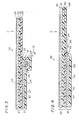
- Opening structure 18 in central member 6 is shown in Figures 2 and 3. Opening structure 18 is the first embodiment of the opening structure that provides a safety opening. In Figure 2, generally at 30, the general relationship among opening structure 18, central member 6 and thin flexible closure member 12 is shown. In Figure 3, generally at 50, the detailed relationship among opening structure 18, central member 6 and closure member 12, and the sealing relationships therebetween is shown.
- opening structure 18 Referring to Figure 3, the formation of opening structure 18, and the sealing relationships between closure member 12 and opening structure 18, and closure member 12 and the top surface of central member 6 will be described.
- an opening is first cut in central member 6. Cut raw edge 66 and portion 68 of central member 6 immediately adjacent to the cut raw edge are bent up and over onto the top surface of central member 6. After bending portion 68 up and over onto central member 6, exposed surface 70 of portion 68 is pressed downwardly in direction C, so that exposed surface 70 is flush with the top surface of central member 6. This provides a safety opening with edge 71 which will not cut or injure the user when removing the hot-fill material from the container.
- Closure member 12 has top lacquer coating layer 52 followed by main support foil layer 54. Disposed on the opposite side of main foil support layer 54 is surlyn layer 56 followed by inside surlyn/lacquer coating layer 58.
- Central member 6 has top lacquer coating layer 60 followed by main foil support layer 62. Disposed on the opposite side of main support foil layer 62 is inside low density polyethylene (LDPE) coating layer 64.
- LDPE low density polyethylene
- the first sealing relationship at 32 is a surlyn/lacquer and LDPE seal between surlyn/lacquer coating 58 and the LDPE of exposed surface 70 of bent over portion 68.
- the second sealing relationship at 34 is a surlyn/lacquer and lacquer seal between surlyn/lacquer coating layer 58 and lacquer coating layer 60 disposed at the top surface of central member 6.
- closure member 82 has top lacquer coating layer 96 followed by main support foil layer 98. Disposed on the opposite side of main support foil layer 98 is surlyn layer 100 followed by inside surlyn/lacquer coating layer 102.
- Central member 84 has top lacquer coating layer 90 followed by main support foil layer 92. Disposed on the opposite side of main support foil layer 92 is inside LDPE coating layer 94.
- Opening structure 86 is formed at the time closure member 82 is heat and pressure sealed over the opening cut in central member 84.
- closure member 82 is heat and pressure sealed over the opening in central member 84, the heat and pressure is adjusted to cause surlyn/lacquer coating layer 102 of closure member 82 and LDPE coating layer 94 of central member 84 to flow together over cut raw edge 88 of the opening.
- surlyn/lacquer coating layer 102 of closure member 82 and LDPE coating layer 94 of central member 84 flow together over cut raw edge 88 of the opening.
- the second sealing relationship at 106 is formed between lacquer coating 90 of central member 84 and surlyn/lacquer coating layer 102 of closure member 82.
- both sealing relationships are broken.
- part of the seal material remains disposed over cut raw edge 88 to provide a safety opening to prevent injury to the user when removing the contents of the hot-fill container.
- the second embodiment of the opening structure can be substituted for the first embodiment of the opening structure at any time. Both embodiments of the opening structure prevent any direct contact between the support foil layers and the hot-fill material in the container.
- Flange member 8 is disposed circumferentially from the peripheral edge of central member 6 disposed circumferentially extending flange member 8.
- Flange member 8 is adapted to lie against the interior wall of the top opening of container 2.
- sealing skirt 10 Circumferentially disposed from the top edge of flange 8 is sealing skirt 10.
- the downwardly extending sealing skirt forms an acute angle with flange 8, as shown in phantom in Figure 2.
- the sealing skirt is driven in direction A, so that it lays against the outside surface of the top end of container 2. This squeezes a portion of the top of container 2 between flange member 8 and sealing skirt 10, which seals the end closure structure to container 2.
- thermoplastic material The outside and inside surfaces of container 2, and the surfaces of flange member 8 and sealing skirt 10 which contact them are all coated with thermoplastic material.
- thermoplastic material When heat and pressure sealing is accomplished, there is a thermoplastic to thermoplastic seal formed between the sealing skirt and the outside surface of the container 2 and flange 8 and the inside surface of container 2, thereby, providing a good oxygen and moisture barrier at the top end of the container.
- Closure member 12 has two sections. First section 14 is sealed to the bent over portion of opening structure 18 and the top surface of central member 6. Second section 16, adjacent to section 14, is not sealed to the top surface of central member 6. Section 16 is pull tab which is used for opening the container. When it is desired to open the container, pull tab 16 is grasped with the fingers and pulled to peel back the closure member 12, thereby, breaking both seals over opening structure 18.
- the process for providing a filled hot-fill container is in accordance with the following procedure for a container having an end closure structure of the first configuration of the first embodiment disposed at the top end of a hot-fill container and a conventional nonflexible end closure at the bottom end of the container.
- Sterilized hot-fill material 36 is disposed in sterilized container 2 at a temperature between 170°F and 205°F to a predetermined level under atmospheric conditions.
- end closure structure 4 is heat and pressure sealed to the top end of container 2. This is also carried out under atmospheric conditions.
- central member 6 has its center section outwardly dished, as shown in Figure 2. It is also to be understood that, if desired, the oxygen can be purged from within the container and replaced with an inert gas, such as nitrogen, or the filling and sealing steps can be carried out in an inert gas field.
- hot-fill material 36 in container 2 cools to ambient temperature
- hot-fill material 36 and the gases in head space 38 reduce in volume.
- This reduction in volume causes a decrease in the pressure within the container.
- the decrease in pressure in the container causes the center section of flexible central member 6 to be drawn in direction B, as shown in Figure 2. Since thin closure member 12 is also flexible, it will easily flex with flexible central member 6 to the position shown in phantom in Figure 2.
- Central member 6 having closure member 12 disposed thereon can be flexed to its inwardly dished position by two methods.
- first method when the hot-fill material has cooled to between 140°F and 160°F, a mechanical means contacts the center section of central member 6 and pushes it in direction B to its inwardly dished position.
- the second method is to allow the drop in pressure to draw the center section central member 6 in direction B to its inwardly disposed position. Since there are two sealing relationships associated with the opening structure, there is little possibility of them breaking when the center section of central member 6 and closure member 12 disposed thereon are flexed inwardly.
- a hot-fill container having the first configuration of the first embodiment of the end closure structure of the invention disposed at the top end of the container and the first configuration of the second embodiment of the end closure structure disposed at the bottom end of the container is shown.
- Flexible central member 114 of end closure structure 112 has an outwardly dished center section. Central member 114 also has opening structure 128 disposed therein. Disposed over opening structure 128 is thin flexible closure member 120 having two sections. First section 122 in a sealing relationship with a bent over portion of opening structure 128 and the top surface of central member 114. Second section 124, adjacent to section 122, is not in a sealing relationship with the top surface of central member 114 and acts as a pull tab for peeling closure member 120 from the end closure structure.
- flange member 116 and sealing skirt 118 cooperate to seal the top end of the container therebetween to provide an oxygen and moisture barrier at the top end of the container.
- Bottom end closure structure,138 is the first configuration of the second embodiment of the end closure structure of the invention.
- Bottom end closure structure 138 has outwardly dished central member 140. Disposed circumferentially from the peripheral edge of central member 140 is downwardly extending flange member 142. Prior to heat and pressure sealing bottom end closure 138 to the bottom end of containers, it is disposed in the open end of container 132 with the outside surface of flange member 142 lying against the inside surface of the container.
- Bottom end closure structure 138 is disposed in container 132 such that portion 135 of container 134 extends below the edge of flange member 142, as shown in phantom in Figure 5.
- a heat and pressure sealing means bends portion 135 inwardly in direction G over the end of flange member 142 so that portion 135 contacts to the inside surface of flange member 142. Flange member 142 is then heat and pressure sealed between the container wall of container 134 and portion 135.
- thermoplastic material The outside and inside surfaces of flange member 142, and the inside surface of container 132 that contacts them are coated with thermoplastic material.
- a thermoplastic to thermoplastic seal is formed between flange member 142 and the surfaces of container 132 that contact the flange member.
- the process for providing a filled hot-fill container is in accordance with the following procedure for a container having a top end closure structure of the first configuration of the first embodiment of the invention disposed at the top end of the container and a bottom end closure structure of the first configuration of the second embodiment disposed at the bottom end of the container.
- bottom end closure structure 138 is heat and pressure sealed to the bottom end of container 132.
- the center section of central member 140 of bottom end closure structure 138 is outwardly dished, as shown in Figure 5.
- hot-fill material 134 in its heated and sterile condition is disposed in sterile container 132 to a predetermined level.
- top end closure structure 112 is heat and pressure sealed to the open top end of container 132.
- hot-fill material 134 cools to ambient temperature
- hot-fill material 134 and gases in head space 136 reduce in volume, thereby, decreasing the pressure within container 132.
- the center section of flexible central member 114 thin flexible with closure member 120 disposed thereon is drawn in direction E.
- the center section of flexible central member 114 with closure member 120 disposed thereon becomes inwardly dished, as shown in phantom, the further reduction in volume and resulting decrease pressure within the container will cause the center section of central member 140 of bottom end closure structure 138 to inwardly dish in direction F.
- a hot-fill container with the second configuration of the first embodiment of the end closure structure of the invention disposed at the top end of the container and a bottom end closure structure of the first configuration of the second embodiment of the invention disposed at the bottom end of the container is shown.
- End closure structure 152 which is the second embodiment of the end closure structure of the invention, has a substantially planar nonflexible central member 154.
- central member 154 is substantially planar, as shown in Figure 6, it is not limited to this shape.
- the central member can have other shapes provided the central member is substantially nonflexible, an opening structure can be defined therein, and a closure member can be sealed over the opening structure such that it is in a first sealing relationship with the opening structure and a second sealing relationship with the top surface of the central member.
- opening structure 166 Disposed in central member 154 is opening structure 166.
- the opening structure is formed by the cut raw edge of the cut opening and a small portion adjacent thereto of central member 154 being bent up and over onto the top surface of central 154.. The bent over portion is pressed downwardly in direction I such that the exposed surface of the bent over portion is flush with the top surface of central member 154. This provides a safety opening for the opening structure.
- Closure member 160 Disposed over the opening in opening structure 166 in central member 154 is closure member 160.
- Closure member 160 has two sections. First section 162 of closure member 160 is in a first sealing relationship with the bent over portion adjacent to the cut raw edge of the opening structure 166 at 168, and in a second sealing relationship with the top surface of planar central member 154 at 170. Section 164 of closure member 160 is not sealed to the top surface of planar central member 154 and is a pull tab. When it is desired to open the container, pull tab 164 is lifted and pulled to cause the thin flexible closure member 160 to peel back to open the container allowing hot-fill material 176 to be removed from the container.
- Bottom end closure member 178 is disposed at the bottom end of container 174 and is the first configuration of the second embodiment of the end closure structure of the invention.
- Bottom closure member 178 is heat and pressure sealed to the open bottom end of container 174.
- Prior to heat and pressure sealing bottom end closure structure 178 at the bottom end of the container it is disposed in container 174 such that flange member 182 lies against the inside surface of container 174.
- Bottom end closure structure is positioned such that portion 175 of container 174 extends below flange member 182. When the bottom end closure is heat and pressure sealed to the container, portion 175 is bent inwardly over the edge of flange member 182 so that portion 175 contacts the inside surface of flange member 182.
- portion 175 is bent inwardly over the edge of flange member 182 and portion 175 contacts the inside surface of flange member 182, heat and pressure sealing means seals the flange 182 between portion 175 and the container wall. This seals bottom end closure 178 to the bottom end of the container.
- thermoplastic material The inside and outside surfaces of flange member 182, and the inside surfaces of container 174 are coated with thermoplastic material.
- thermoplastic to thermoplastic seal formed between the outside and inside surfaces of the flange member and the surfaces of the container wall and portion 175 that contact them. This forms an oxygen and moisture barrier at the bottom of the container.
- Bottom end closure structure 178 has central member 180 that with an outwardly dished center section.
- the center section is outwardly dished a predetermined amount so that when it is flexed inwardly, as shown in phantom in Figure 6, and hot-fill material 126 and the gases in head space 172 cool to ambient temperature, there is substantially atmospheric pressure or slight vacuum pressure within container 174.
- the process for providing a filled hot-fill container is in accordance with the following procedure for a container having the second configuration of the first embodiment of the end closure structure of the invention disposed at the top end of the container and a bottom end closure structure of the first configuration of the second embodiment of the end closure structure of the invention disposed at the bottom end of the container.
- hot-fill material 176 and gases in head space 172 cool to ambient temperature
- hot-fill material 176 and the gases in head space 172 reduce in volume, thereby, causing a decrease in pressure within the container.
- the center section of flexible central member 180 of bottom end closure structure 178 is drawn in direction H.
- hot-fill material 176 and the gases in head space 172 cool to ambient temperature with the central member 180 inwardly dished, as shown in phantom in Figure 6, there is substantially atmospheric pressure or slight vacuum pressure within container 174 to prevent stress on the sealing relationships associated with the opening structure, the top surface of the central member and thin flexible disposed oT-er the opening structure.
- FIG. 7 a cross-sectional view of the second configuration of the second embodiment of the end closure structure of the invention is shown disposed at the bottom end of a hot-fill container.
- Bottom end closure structure 202 disposed at the bottom end of hot-fill container 210 is the second configuration of the second embodiment of the end closure structure of the invention.
- Bottom end closure structure 202 has flexible central member 204 with an outwardly dished center section.
- the center section is outwardly dished the same predetermined amount as the center section of the central member of the first configuration of the second embodiment to allow for substantially atmospheric pressure or slight vacuum pressure within container 210 after the center section is flexed inwardly in direction J, shown in phantom, after the hot-fill material 212 and the internal gases cool to ambient temperature.
- the main difference between the first and second configurations of the second embodiment of the end closure structure is the means disposed at the peripheral edge of the central member for sealing the end closure structure to the container.
- the second configuration of the second embodiment of the end closure structure uses means similar to those described for the first and second configuration of the first embodiment for sealing the end closure structure 202 at the bottom of container 210.
- sealing skirt 208 Disposed circumferentially from the pheripheral edge of central member 204 is downwardly extending flange member 206. Disposed circumferentially the edge of flange member 206 is upwardly extending sealing skirt 208. Prior to heat and pressure sealing bottom end closure structure 202 to container 210, sealing skirt 208 forms an acute angle with flange member 206. When bottom end closure structure 202 is to be heat and pressure sealed to the bottom of container 210, end closure structure 202 is positioned such that flange member 206 lies against the inside surface of container 210, and the sealing skirt is disposed over the end of container 210 and extends angularly upward therefrom.
- a heat and pressure sealing means engages end closure structure 202 and drives sealing skirt 208 against the outside surface of container 210, thereby sealing the end of the container between flange member 206 and sealing skirt 208. Since the surfaces of container 210, the surfaces of flange member 206 and the surfaces of sealing skirt 208 are coated with thermoplastic material, a good oxygen and moisture barrier is formed when end closure structure 202 is heat and pressure sealed to the bottom of container 210. It is to be understood that the second configuration of the second embodiment can be substituted for the first configuration of the second embodiment at any time.
Landscapes
- Engineering & Computer Science (AREA)
- Mechanical Engineering (AREA)
- Closures For Containers (AREA)
- Closing Of Containers (AREA)
- Rigid Containers With Two Or More Constituent Elements (AREA)
- Containers Opened By Tearing Frangible Portions (AREA)
Applications Claiming Priority (2)
| Application Number | Priority Date | Filing Date | Title |
|---|---|---|---|
| US06/642,054 US4557398A (en) | 1984-08-17 | 1984-08-17 | End closure structure for a container |
| US642054 | 1984-08-17 |
Publications (2)
| Publication Number | Publication Date |
|---|---|
| EP0171498A2 true EP0171498A2 (de) | 1986-02-19 |
| EP0171498A3 EP0171498A3 (de) | 1987-10-21 |
Family
ID=24574989
Family Applications (1)
| Application Number | Title | Priority Date | Filing Date |
|---|---|---|---|
| EP85102920A Withdrawn EP0171498A3 (de) | 1984-08-17 | 1985-03-14 | Verschlussvorrichtung für einer Behälteröffnung |
Country Status (5)
| Country | Link |
|---|---|
| US (1) | US4557398A (de) |
| EP (1) | EP0171498A3 (de) |
| JP (1) | JPS6160448A (de) |
| KR (1) | KR860001752A (de) |
| CA (1) | CA1230564A (de) |
Cited By (2)
| Publication number | Priority date | Publication date | Assignee | Title |
|---|---|---|---|---|
| EP0185516B1 (de) * | 1984-12-14 | 1989-03-08 | Toyo Seikan Kaisha Limited | Hermetisch gesiegelter Verschluss |
| US11491164B2 (en) | 2004-05-23 | 2022-11-08 | HMI Medical Innovations, LLC | Theramutein modulators |
Families Citing this family (33)
| Publication number | Priority date | Publication date | Assignee | Title |
|---|---|---|---|---|
| US4680917A (en) * | 1984-08-17 | 1987-07-21 | International Paper Company | Process for providing filled containers |
| CH674829A5 (de) * | 1987-12-14 | 1990-07-31 | Alcan Rorschach Ag | |
| JPH05502649A (ja) * | 1989-12-18 | 1993-05-13 | ポリスター・パッケイジング・インコーポレイテッド | 容器閉鎖装置及びその製造方法 |
| JP2981760B2 (ja) * | 1990-07-10 | 1999-11-22 | 武 照井 | 複数合成式の飲料缶 |
| FR2735749B1 (fr) * | 1995-06-22 | 1997-08-29 | Metal Box Plc | Boite metallique a ouverture partielle, procede et machine de fabrication d'une telle boite |
| USD397586S (en) | 1997-02-24 | 1998-09-01 | Le Creuset Sa | Container with closure for liquid and food |
| GB2375531A (en) | 2001-05-17 | 2002-11-20 | Insulpak Ltd | Container lid |
| US7169418B2 (en) | 2001-06-04 | 2007-01-30 | The Procter And Gamble Company | Packaging system to provide fresh packed coffee |
| USD478006S1 (en) | 2001-08-06 | 2003-08-05 | Solo Cup Company | Reclosable container lid |
| US6732875B2 (en) | 2001-08-06 | 2004-05-11 | Solo Cup Company | Reclosable container lid |
| USD477223S1 (en) | 2001-08-06 | 2003-07-15 | Solo Cup Company | Reclosable container lid |
| US7246715B2 (en) | 2001-08-06 | 2007-07-24 | Solo Cup Operating Corporation | Reclosable container lid |
| US6679397B2 (en) | 2001-08-06 | 2004-01-20 | Solo Cup Company | Container lid with closure member |
| US7131551B2 (en) | 2001-08-06 | 2006-11-07 | Solo Cup Company | Container lid with closure member |
| US7731047B2 (en) * | 2001-08-06 | 2010-06-08 | Solo Cup Operating Corporation | Reclosable container lid with sliding element |
| CA2466459C (en) * | 2001-11-13 | 2011-06-14 | Dart Container Corporation | Recloseable lid with closure plug |
| GB0130619D0 (en) | 2001-12-20 | 2002-02-06 | Insulpak Ltd | A Lid |
| USD476891S1 (en) | 2001-12-20 | 2003-07-08 | Solo Cup Company | Container lid |
| USD485758S1 (en) | 2002-06-07 | 2004-01-27 | Solo Cup Company | Container lid |
| KR200289188Y1 (ko) * | 2002-06-11 | 2002-09-13 | 전정욱 | 오픈 기능성이 개선된 캔뚜껑 |
| US6988642B2 (en) * | 2002-10-29 | 2006-01-24 | Johnson & Johnson Consumer Companies | Tamper-evident dispenser bottle |
| USD514445S1 (en) | 2003-07-18 | 2006-02-07 | Solo Cup Company | Reclosable container lid |
| USD514444S1 (en) | 2003-07-18 | 2006-02-07 | Solo Cup Company | Reclosable container lid |
| US20050109784A1 (en) * | 2003-11-24 | 2005-05-26 | Sonoco Development, Inc. | Easy-open container and closure assembly therefor |
| TWI322124B (en) * | 2004-03-04 | 2010-03-21 | Murray Melrose David | Headspace sealing and displacement method for removal of vacuum pressure |
| CA2633465A1 (en) * | 2005-12-21 | 2007-06-28 | Columbus E. Aps | Disposable beverage can |
| UA99944C2 (ru) | 2008-01-18 | 2012-10-25 | Краун Пекеджинг Текнолоджи, Инк. | Крышка консервной банки |
| TWI472459B (zh) | 2008-05-19 | 2015-02-11 | Melrose David | 移除真空壓力之頂部空間改性方法及其裝置 |
| ES2366162T3 (es) | 2008-09-04 | 2011-10-17 | Crown Packaging Technology, Inc | Tapa de lata. |
| JP5750882B2 (ja) * | 2009-12-25 | 2015-07-22 | 東洋製罐株式会社 | 密封容器及びその製造方法 |
| HUE029731T2 (en) * | 2010-11-29 | 2017-03-28 | Crown Packaging Technology Inc | Clasps |
| ES2615331B1 (es) * | 2015-12-03 | 2018-03-13 | Mecánica Y Tecnología Alimentaria, S.L. | Tapa para envases de producto dosificado en caliente y dispositivo para su fabricación |
| WO2019112051A1 (ja) * | 2017-12-07 | 2019-06-13 | 日本製鉄株式会社 | ヒートシール蓋及び缶 |
Family Cites Families (67)
| Publication number | Priority date | Publication date | Assignee | Title |
|---|---|---|---|---|
| US717711A (en) * | 1902-07-18 | 1903-01-06 | Automatic Vacuum Canning Company | Process of vacuum-sealing sheet-metal cans or vessels. |
| US2147004A (en) * | 1937-09-22 | 1939-02-14 | Wark Samuel Arnold | Beer can |
| US2293142A (en) * | 1940-08-03 | 1942-08-18 | Johnson Ogden | Container and method of making containers |
| US2340473A (en) * | 1941-03-18 | 1944-02-01 | Johnson Ogden | Container |
| US2379043A (en) * | 1942-12-21 | 1945-06-26 | Gen Foods Corp | Container |
| US2629534A (en) * | 1947-10-08 | 1953-02-24 | Julian L Reynolds | Container |
| US2870935A (en) * | 1955-01-27 | 1959-01-27 | Suzanne Kaaren Blackmer | Container seal |
| US2894844A (en) * | 1956-10-31 | 1959-07-14 | Pabst Brewing Co | Canning process and product |
| US3135451A (en) * | 1960-02-11 | 1964-06-02 | Fr Hesser Maschinenfabrik Ag F | Packaging container |
| US3057537A (en) * | 1960-11-17 | 1962-10-09 | Pollick Frank | Cover for paper coffee cup |
| BE644299A (de) * | 1963-02-25 | |||
| US3274964A (en) * | 1964-02-12 | 1966-09-27 | Ekco Containers Inc | Re-closable hermetically sealed container |
| US3355059A (en) * | 1964-05-13 | 1967-11-28 | American Can Co | Laminate with severable portion |
| US3302818A (en) * | 1964-05-13 | 1967-02-07 | American Can Co | Container with easy-open end |
| US3281024A (en) * | 1964-05-20 | 1966-10-25 | Continental Can Co | Easy opening container end and closure member therefor |
| US3312368A (en) * | 1964-09-09 | 1967-04-04 | Reynolds Metals Co | Easy-open can end |
| US3292828A (en) * | 1964-09-17 | 1966-12-20 | Nat Can Corp | Easy opening can end |
| US3361611A (en) * | 1965-04-05 | 1968-01-02 | Tetra Pak Ab | Method of covering a stamped hole in a laminated packaging material by means of a wafer or the like, and a package to which the method has been applied |
| US3339788A (en) * | 1965-10-22 | 1967-09-05 | Nat Can Corp | Container |
| SE314578B (de) * | 1966-04-12 | 1969-09-08 | Tetra Pak Ab | |
| US3380622A (en) * | 1966-12-15 | 1968-04-30 | Procter & Gamble | Method and material for hermetically sealing containers |
| US3389827A (en) * | 1967-04-10 | 1968-06-25 | Minnesota Mining & Mfg | Easy-open container and sealing tape |
| DE1586488A1 (de) * | 1967-05-06 | 1972-01-27 | Bellaplast Gmbh | Duennwandiger Behaelter aus Kunststoff mit luftdichtem Verschluss |
| US3547305A (en) * | 1968-11-15 | 1970-12-15 | Continental Can Co | Easy opening container |
| US3731835A (en) * | 1971-08-03 | 1973-05-08 | Continental Can Co | Easy opening container |
| CH557268A (de) * | 1972-10-18 | 1974-12-31 | Rausing Anders Ruben | Einweg-verpackungsbehaelter. |
| CH562135A5 (de) * | 1973-02-20 | 1975-05-30 | Tetra Pak Dev | |
| US3871550A (en) * | 1973-05-29 | 1975-03-18 | Continental Can Co | Push-in easy opening container |
| US3952911A (en) * | 1973-06-08 | 1976-04-27 | Continental Can Company, Inc. | Non-detachable and reclosable easy opening container closure structure |
| DE2355550A1 (de) * | 1973-11-07 | 1975-10-02 | Bosch Gmbh Robert | Aufreissbehaelter |
| US3977591A (en) * | 1974-06-28 | 1976-08-31 | Ab Ziristor | Cover strip for the pouring opening in a packing container |
| US3908857A (en) * | 1974-10-15 | 1975-09-30 | Continental Can Co | Tape seal for container |
| US4029033A (en) * | 1974-09-18 | 1977-06-14 | The Continental Group, Inc. | Convenience opening of containers for liquid products |
| US4024980A (en) * | 1974-11-08 | 1977-05-24 | Crown Cork & Seal Company, Inc. | Easy opening can end having a closure plug |
| US3958717A (en) * | 1975-08-15 | 1976-05-25 | Jos. Schlitz Brewing Company | Lid construction for a container |
| US4034132A (en) * | 1975-09-25 | 1977-07-05 | The Continental Group, Inc. | Propylene polymer adhered to enamel coated metal surface |
| US3990603A (en) * | 1975-12-09 | 1976-11-09 | Minnesota Mining And Manufacturing Company | Easy open closure system |
| CH593180A5 (de) * | 1976-02-11 | 1977-11-30 | Sandherr Max Ag | |
| CH598063A5 (de) * | 1976-05-07 | 1978-04-28 | Sandherr Max Ag | |
| US4036397A (en) * | 1976-09-07 | 1977-07-19 | Christiana Metals Corporation | Container with easy open top |
| US4054228A (en) * | 1977-04-01 | 1977-10-18 | American Can Company | Can end closure having first and second sealing means |
| US4135637A (en) * | 1978-02-07 | 1979-01-23 | Minnesota Mining And Manufacturing Company | Center venting closure system |
| US4108330A (en) * | 1977-06-08 | 1978-08-22 | Minnesota Mining And Manufacturing Company | Easy open container end assembly |
| US4116359A (en) * | 1977-10-21 | 1978-09-26 | The Continental Group, Inc. | Through hole deformation and inside sealing tear strip |
| CH623534A5 (de) * | 1978-02-15 | 1981-06-15 | Hoffmann Ag Geb | |
| CH627994A5 (en) * | 1978-05-08 | 1982-02-15 | Sandherr Max Ag | Container |
| US4232797A (en) * | 1979-05-14 | 1980-11-11 | Waterbury Nelson J | Reclosable container |
| CH629983A5 (de) * | 1978-06-06 | 1982-05-28 | Alusuisse | Verfahren zur herstellung von deckelringen fuer konservendosen. |
| DE2835638A1 (de) * | 1978-08-14 | 1980-02-21 | Milupa Ag | Deckel und/oder boden einer dose, insbesondere zylindrischen dose |
| US4170314A (en) * | 1978-10-11 | 1979-10-09 | The Continental Group, Inc. | Container closure |
| US4163506A (en) * | 1978-10-23 | 1979-08-07 | Minnesota Mining And Manufacturing Company | Closure assembly having a tear template |
| US4176760A (en) * | 1978-12-08 | 1979-12-04 | The Continental Group, Inc. | Easy opening container unit having a domed end panel |
| FR2452650A1 (fr) * | 1979-03-28 | 1980-10-24 | Itw De France | Procede et dispositif d'obturation etanche pour trous, orifices et ouvertures pratiques dans des panneaux |
| JPS5819535B2 (ja) * | 1979-04-16 | 1983-04-19 | 本州製紙株式会社 | 密封容器のシ−ル方法 |
| CH636820A5 (de) * | 1979-06-18 | 1983-06-30 | Sandherr Max Ag | Dosenverschluss. |
| US4215791A (en) * | 1979-08-06 | 1980-08-05 | Minnesota Mining And Manufacturing Company | Easy open closure system |
| US4253585A (en) * | 1979-09-25 | 1981-03-03 | Universal Instruments Corporation | Dip component supply magazine |
| GB2067253A (en) * | 1980-01-11 | 1981-07-22 | United Carr Ltd | Aperture plug |
| CH643502A5 (de) * | 1980-03-25 | 1984-06-15 | Alusuisse | Metalldose mit membranverschluss. |
| EP0059635B1 (de) * | 1981-03-02 | 1985-06-05 | Toyo Seikan Kaisha Limited | Leicht zu öffnender Verschluss für Behälter und Verfahren zu dessen Herstellung |
| US4372460A (en) * | 1981-05-18 | 1983-02-08 | Minnesota Mining And Manufacturing Company | Oil-resistant closure system |
| US4378074A (en) * | 1981-05-18 | 1983-03-29 | Minnesota Mining And Manufacturing Company | Easy open closure system |
| JPS57202911A (en) * | 1981-06-08 | 1982-12-13 | Ishikawajima Harima Heavy Ind Co Ltd | Method and device for roll shifting of rolling mill |
| JPS5926557B2 (ja) * | 1981-11-12 | 1984-06-28 | 凸版印刷株式会社 | 容器の高温充填密閉方法 |
| AU554618B2 (en) * | 1981-06-19 | 1986-08-28 | American National Can Corp. | Hot hilled container and method |
| US4407429A (en) * | 1982-04-21 | 1983-10-04 | The Continental Group, Inc. | Cap for and in combination with a container |
| JPS58216586A (ja) * | 1982-06-01 | 1983-12-16 | 凸版印刷株式会社 | 容器の高温液体充填方法 |
-
1984
- 1984-08-17 US US06/642,054 patent/US4557398A/en not_active Expired - Fee Related
-
1985
- 1985-03-14 EP EP85102920A patent/EP0171498A3/de not_active Withdrawn
- 1985-03-27 KR KR1019850002035A patent/KR860001752A/ko not_active Withdrawn
- 1985-04-08 JP JP60074162A patent/JPS6160448A/ja active Pending
- 1985-04-12 CA CA000478982A patent/CA1230564A/en not_active Expired
Cited By (2)
| Publication number | Priority date | Publication date | Assignee | Title |
|---|---|---|---|---|
| EP0185516B1 (de) * | 1984-12-14 | 1989-03-08 | Toyo Seikan Kaisha Limited | Hermetisch gesiegelter Verschluss |
| US11491164B2 (en) | 2004-05-23 | 2022-11-08 | HMI Medical Innovations, LLC | Theramutein modulators |
Also Published As
| Publication number | Publication date |
|---|---|
| KR860001752A (ko) | 1986-03-22 |
| EP0171498A3 (de) | 1987-10-21 |
| JPS6160448A (ja) | 1986-03-28 |
| US4557398A (en) | 1985-12-10 |
| CA1230564A (en) | 1987-12-22 |
Similar Documents
| Publication | Publication Date | Title |
|---|---|---|
| US4557398A (en) | End closure structure for a container | |
| US4680917A (en) | Process for providing filled containers | |
| US4542029A (en) | Hot filled container | |
| US4685273A (en) | Method of forming a long shelf-life food package | |
| EP0068718B1 (de) | Hermetisch versiegelbare Behälter und Verfahren zum Versiegeln | |
| US3122990A (en) | Fried | |
| US3402874A (en) | Container closure | |
| US6739500B1 (en) | Container and method for making container for fragile products | |
| US3955699A (en) | Close nesting, tamperproof container closure | |
| US3087823A (en) | Package | |
| US3345798A (en) | Method and apparatus for making and applying closures | |
| US3096904A (en) | Sealed plastic containers | |
| WO2021007205A1 (en) | Container construction with flexible liner and one-way valve | |
| EP0208352A1 (de) | Deckel für einen Behälter und aus einem Behälter mit einem Deckel bestehende Verpackung | |
| US5169017A (en) | Can end closure apparatus | |
| JPH0575629B2 (de) | ||
| US3439587A (en) | Closure and methods and apparatus for making same | |
| US3208626A (en) | Container closure and package including same | |
| US12017837B2 (en) | Container construction with elevating bag | |
| EP0642454A1 (de) | Behälter | |
| EP0229420B1 (de) | Heissfüllung eines Plastikbehälters | |
| EP1013562A2 (de) | Eine Schale, ein Dichtungsband und einen Deckel enthaltender Behälter | |
| GB2152469A (en) | Stackable container with dilutable product | |
| EP0224316B1 (de) | Heissfüllung eines thermoplastischen Behälters | |
| IE42914B1 (en) | Container having a removable lid |
Legal Events
| Date | Code | Title | Description |
|---|---|---|---|
| PUAI | Public reference made under article 153(3) epc to a published international application that has entered the european phase |
Free format text: ORIGINAL CODE: 0009012 |
|
| AK | Designated contracting states |
Designated state(s): CH DE FR GB IT LI SE |
|
| PUAL | Search report despatched |
Free format text: ORIGINAL CODE: 0009013 |
|
| AK | Designated contracting states |
Kind code of ref document: A3 Designated state(s): CH DE FR GB IT LI SE |
|
| STAA | Information on the status of an ep patent application or granted ep patent |
Free format text: STATUS: THE APPLICATION IS DEEMED TO BE WITHDRAWN |
|
| 18D | Application deemed to be withdrawn |
Effective date: 19871001 |
|
| RIN1 | Information on inventor provided before grant (corrected) |
Inventor name: RYCHIGER, PETER Inventor name: HAMBLETON, THOMAS P. Inventor name: GUEVARA, ERICK |