EP0171586B2 - Reibungsbremse an Fahrzeug-Anhängerkupplungen - Google Patents
Reibungsbremse an Fahrzeug-Anhängerkupplungen Download PDFInfo
- Publication number
- EP0171586B2 EP0171586B2 EP85108347A EP85108347A EP0171586B2 EP 0171586 B2 EP0171586 B2 EP 0171586B2 EP 85108347 A EP85108347 A EP 85108347A EP 85108347 A EP85108347 A EP 85108347A EP 0171586 B2 EP0171586 B2 EP 0171586B2
- Authority
- EP
- European Patent Office
- Prior art keywords
- coupling
- trailer
- arms
- ball
- friction brake
- Prior art date
- Legal status (The legal status is an assumption and is not a legal conclusion. Google has not performed a legal analysis and makes no representation as to the accuracy of the status listed.)
- Expired - Lifetime
Links
Images


Classifications
-
- B—PERFORMING OPERATIONS; TRANSPORTING
- B60—VEHICLES IN GENERAL
- B60D—VEHICLE CONNECTIONS
- B60D1/00—Traction couplings; Hitches; Draw-gear; Towing devices
- B60D1/24—Traction couplings; Hitches; Draw-gear; Towing devices characterised by arrangements for particular functions
- B60D1/242—Traction couplings; Hitches; Draw-gear; Towing devices characterised by arrangements for particular functions for supporting braking actions, e.g. braking means integrated with hitches; Braking sensors
-
- B—PERFORMING OPERATIONS; TRANSPORTING
- B60—VEHICLES IN GENERAL
- B60D—VEHICLE CONNECTIONS
- B60D1/00—Traction couplings; Hitches; Draw-gear; Towing devices
- B60D1/01—Traction couplings or hitches characterised by their type
- B60D1/06—Ball-and-socket hitches
- B60D1/065—Ball-and-socket hitches characterised by the hitch mechanism
-
- B—PERFORMING OPERATIONS; TRANSPORTING
- B60—VEHICLES IN GENERAL
- B60D—VEHICLE CONNECTIONS
- B60D1/00—Traction couplings; Hitches; Draw-gear; Towing devices
- B60D1/24—Traction couplings; Hitches; Draw-gear; Towing devices characterised by arrangements for particular functions
- B60D1/30—Traction couplings; Hitches; Draw-gear; Towing devices characterised by arrangements for particular functions for sway control ; Sway alarm means
- B60D1/32—Traction couplings; Hitches; Draw-gear; Towing devices characterised by arrangements for particular functions for sway control ; Sway alarm means involving damping devices
Definitions
- the invention relates to a vehicle trailer hitch with a friction brake, consisting of a coupling ball and a ball coupling housing comprising this, partial sections of the inner surface of the ball coupling housing having mutually opposite recesses, in which friction brake blocks are arranged, which can be pressed by actuating elements against the surface of the coupling ball , wherein the recesses of the ball coupling housing are designed as circular openings, in which the friction brake pads are piston-like, floating, guided by the inside surfaces of the openings, held under elastic spring pressure.
- Friction brakes of this type serve to dampen vibrations that occur within the degrees of freedom of movement of the coupling ball housing around the ball while both vehicles are traveling in train mode and are manifested in yaw-pitching and rolling movements, so-called rolling movements.
- GB-A-1 380 051 also discloses two further forms of vehicle trailer coupling design in which the friction brake blocks are spring-loaded.
- the ball coupling housing consists of hinge-like housing halves which enclose the coupling ball and which themselves act as friction brake blocks. The friction force is applied symmetrically and constantly to the coupling ball with the aid of friction surfaces which are provided on the inside directly on the housing halves themselves.
- the two interconnected halves of the coupling ball housing not only transmit the frictional forces elastically to the coupling ball, but at the same time must be firmly locked together so that the actual coupling function of the ball coupling housing between vehicle and trailer is reliably ensured.
- the invention has for its object to improve the generic design of a vehicle trailer hitch so that the friction brake pads are not only constantly pressurized during operation and their different wear is taken into account by automatic adjustment, but also the possibility of easy operation and adjustability of this Friction brake blocks is created from the outside.
- the friction brake pads have the carrier, which can be acted upon symmetrically on the back by the arms of a collet, which comprise an arch, the front circumferential side of the ball coupling housing, firmly connected to this clamp and at the ends of the caliper arms exists, and in which known adjusting, clamping and fixing elements are arranged between the tong arms.
- This arrangement and design of a pair of pliers on the ball coupling housing in addition to a simple design, provides easy access to the actuating elements for setting and maintenance of the actuating, tensioning and fixing elements, since these are likewise arranged outside the ball coupling housing.
- parts of the coupling ball can be designed as counter friction surfaces for the friction surfaces of the friction brake pads.
- the carriers of the friction brake pads can be expediently detachably connected to the arms of the collet.
- the actuating, tensioning and fixing elements can also have a motor drive with remote control and display and also a quick release device known per se. "
- the friction brake according to the invention has an effective damping of all vibrations within the degrees of freedom of the already with low coefficients of friction of 0.2 to 0.3 and relatively low application pressures in single-axle trailer vehicles, particularly in the weight class 0.75-3 t Ball coupling achieved. These effects were affected to a small extent by a wet or greasy surface of the coupling ball. Since the friction brake is located on the coupling ball housing on the drawbar of the trailer vehicle, it is also possible to adjust the size of the friction brake pads to the weight of the trailer vehicle, while the corresponding coupling ball on the tractor vehicle can always be the same.
- the setting and fixing elements between the arms of the clamping fork or collet arranged on the coupling housing can consist of a threaded spindle with a scale marking indicating the set pressure or from a wedge adjustment.
- the spindle can also be driven by remote control, whereby the set pressure can be read off via remote display in the towing vehicle. It is also conceivable to change the setting as a function of the respective speed of the towing vehicle using an automatic system.
- the arms can be biased by springs or gas springs and the quick release device can consist of a known toggle lever lock.
- the coupling socket consists of a U-bracket, the U-web of which forms the spherical section-shaped support surface
- a wedge-shaped sliding wedge arranged in the ball coupling housing can act on the back of the web of the U-bracket with its wedge surface.
- the sliding wedge can be arranged at the lower end of a push rod guided in a sleeve extension standing on the extension of the ball coupling housing, the other end of which carries a thread which is seated in a rotating nut mounted on the sleeve extension, the sliding wedge is supported on the back by a slide stop arranged in the ball coupling housing.
- the rotating nut can have one or more single-arm radial adjusting levers. Furthermore, there is the possibility of making the sliding wedge displaceable and fixable relative to the push rod in its longitudinal axis. As the invention further provides, the sliding wedge can also be brought to the rear of the web of the U-bracket via the adjusting elements of the coupling socket in and out of the loading position.
- the design of the friction brake can, as the invention further provides, be developed in such a way that a uniform, constant pressure of the arms of the collet on the friction brake blocks is maintained under the above-mentioned stresses and this pressure does not undergo any significant change due to the wear of the friction brake blocks.
- the clamping elements consist of gas springs which press the ends of the arms of the collet away from one another.
- the clamping elements consist of gas springs which press the ends of the arms of the collet away from one another.
- the center sections of the arms are angled and crosswise one above the other and pass into approximately parallel end sections.
- the arms can also be designed as two-armed levers with a swivel joint arranged in a region between the center of the coupling ball and the ends of the arms.
- the gas spring between the ends of the arms of the collet maintains the contact pressure of the friction brake pads on the counter friction surface of the coupling ball even with shock loads due to its shock absorber effect and does not change this pressure even if the distance between the two ends of the arms of the collet changes due to the wear of the Friction pads of the friction brake pads enlarged.
- the gas spring is articulated to the end section of one of the arms in the embodiments of the friction brake described above and can be releasably inserted with the other end into a recess which forms an articulated eye which is open on one side.
- To open this connection of the two arms i.e. To release the friction brake, it is necessary with this design to compress the gas spring by hand and remove one end of it from the hinge eye. This handling sometimes brings difficulties for the user, especially if the housing of the gas spring is wet or coated with greasiness.
- this type of construction forces the gas spring with its bumper to be articulated firmly to one end section and to attach the joint pin intended for the open joint eye to the cylinder end of the spring.
- the steering axis of the two-armed lever which can be brought into and out of the dead center position can be supported in a bearing block which can be pivoted at a radial distance about a bearing pin-shaped extension of the end sections of the arms, this bearing pin-shaped extension about an approximately perpendicular to the bearing pin axis Axis is pivotally hinged to the end portions of the arms, wherein the bearing pin-shaped extension can consist of a bearing pin placed on a U-link hinged to the end portions.
- a hand lever can be used, which is pivotally mounted in the bearing block about an axis approximately perpendicular to the handlebar axis.
- a further possibility of arranging the arm is to arrange a hand lever lying approximately parallel to the longitudinal axis of the gas spring outside the end sections of both arms.
- This design allows the end sections of the two arms, which are pushed apart by the gas spring via the two-armed lever in the dead center position of the articulation point of the lever and acted upon by the tension of the gas spring, by simply pivoting the two-armed lever by means of the hand lever while overcoming the dead center position from the application pressure relieve the gas spring and open the articulated connection.
- the connection can be established and secured just as easily by pivoting the two-armed lever into the dead center position.
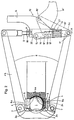
- the coupling ball housing 2 comprising the coupling ball 1, here circularly shaped, opposite openings 2a, in which the friction brake pads 4 on the inner side walls of the openings 2a with their circular disk-shaped carriers 5 whose inner side walls are guided like a piston.
- the surface 4a of the brake blocks 4 which acts on the surface of the coupling ball 1 is curved in a concave manner in the manner of a spherical segment.
- the outwardly facing circular surface of the carrier 5 of the friction brake pads 4 is acted upon (see FIG.
- both gun arms 6 are connected here by a threaded spindle with a threaded nut 10, a lever clamp 12 and the biasing spring 13.
- the lever clamp 13 consists of a clamping lever 14 which is pivotally connected to a double bracket 16 by means of pivot pin 15, which can be pivoted with a spacer pin 17 into a coupling recess 6c of the pincer arm 6 facing away from the spindle 9.
- the tensioning lever 14 In the direction away from the spindle 9, at a distance from the rotary bolts 15, the tensioning lever 14 has a clamping stop piece 18, which is bolt-shaped here and which, in the direction of the center axis of the spindle 9, in a slot guide pair 19 provided in the frame 20 carrying the spindle nut 10 in the direction of the center axis of the spindle 9 is movable back and forth.
- the clamping stop piece 18 is acted upon by the biasing spring 13, which is supported in the frame 20 carrying the spindle nut 10.
- the tensioning lever 14 can be pivoted from the tensioning position shown in full lines in FIG. 2 into the end tensioning position indicated by dash-dotted lines around the spacer bolt 17, the double bracket 16 moving into the end position 16 'and the tensioning stop piece 18 in the slot guide 19 a - here lower - position in the direction of the spindle 19 out in the upper position 18 ', so that the bias spring 13 relaxes and thus also the pressure of the curved lugs 6a, the caliper arms 6 on the carrier 5 of the friction brake pads 4 is canceled becomes.
- the span length of the biasing spring which can be adjusted in the tensioned position of the lever tension lock 12 by turning the spindle or the spindle nut 10, is readable by a scale 21 arranged on the frame 20 and a display wedge 23 arranged on a cover plate 22 of the biasing spring 13.
- a return leg spring 24 placed around the axle pin of the joint 7 of the caliper arm 6 acts on the rear side of the carrier 5 for the friction brake blocks 4 and thus prevents the friction brake blocks 4 from slipping out of the openings 2a of the coupling ball housing 2 that guide them.
- the coupling ball housing 2 has a rear extension 2d in or on which the actuating and adjusting elements 41, 42 and 43 are arranged, with the aid of which the coupling socket 45 points to the coupling ball (not shown) and can be moved and locked away from it.
- the coupling socket 45 is designed here as the web of a U-bracket (FIG. 2) with the bracket arms 45a.
- the coupling socket 45 has a friction-enhancing surface of the spherical section-shaped contact surface 45b and also the inner surface 2m of the coupling ball housing 2 opposite this surface.
- a sleeve extension 47 is fixedly mounted on the extension 2d of the coupling ball housing, in which a push rod 48 is slidably mounted on the lower one End carries a sliding wedge 49, the wedge surface 49a of which can be placed against the rear of the coupling socket 45 and which is supported on the back by a sliding stop 50 projecting between the bracket arms 45b on the extension 2d of the ball coupling housing 2.
- the push rod 48 has at its upper end a thread 48a which is seated in a rotary nut 51 which rotatably supports in the sleeve shoulder 47 and has a radial adjusting lever 52.
- the push rod 45 can be turned by turning the rotating nut 51 Moved upward in the direction of the arrow shown and thus the coupling socket 45 is pressed against the coupling ball via the sliding wedge 49 and its wedge surface 49a.
- the contact pressure can be increased or decreased according to the respective requirements.
- the Push rod 45 with the sliding wedge 49 are initially moved so far downwards against the direction of the arrow mentioned by turning the rotating nut 51 that the 45 can move backwards (to the right in the drawing) into its starting position before the vehicle clutch then moves can be solved.
- the sliding wedge 49 can also be arranged in a manner not shown in such a way that it can be displaced and fixed relative to the push rod 48 in its longitudinal axis, i.e. he can then from a position determined by the position of the rotary nut 51 z. B. push the drawn down and thus the retraction path of the coupling socket 45 are released.
- the sliding wedge 49 can then be brought back into the (drawn) position relative to the push rod 45 in that he was before.
- Such a movement of the sliding wedge 49 can also be connected to the movement of the elements 40, 41, 42 via corresponding connecting levers in the form of a positive control.
- the coupling ball housing 2 comprising the coupling ball 1 has circular, opposing openings 2a, in which the friction brake blocks 4 on the inside walls of the openings 2a are guided in a piston-like manner with their circular-shaped carriers 5 on their inside walls .
- the surface 4a of the friction brake pads 4 which acts on the surface of the coupling ball 1 is curved in a concave manner in the manner of a spherical segment.
- the outwardly facing circular surfaces of the two carriers 5 of the friction brake blocks 4 are acted upon by the curved lugs 6a of the initial sections 6 'of the two caliper arms 6.
- These initial sections 6 ' are articulated in a region in front of the center M of the coupling ball 1 and laterally thereof with swivel joints 7, here at the ends of a clamp 8 firmly connected to the ball coupling housing.
- the central sections 6 "of both tong arms 6 are angled crosswise one above the other and merge into approximately parallel end sections 6" '. Between the two end sections 6 "'there is the gas spring 10, the bumper 10a and the cylinder housing 10b of which is connected in an articulated manner to one or the other end section 6"' of the tong arms 6, one of these articulated connections, here that of the cylinder housing 10b , is releasably insertable into a U-recess 6b.
- the position of the caliper arms 6 shown in full lines corresponds to the position which results when fresh friction brake pads 4 are not yet worn, the distance between the two end sections 6 ′′ then corresponds to the smallest distance, and the position of the caliper arms 6 shown in broken lines shows a distance D2, which sets in when the wear of the brake pads has reached its greatest level.
- the coupling ball housing 2 which comprises the coupling ball 1 has circular, opposite openings 2a, in which the friction brake blocks 4 on the inner side walls of the openings 2a are guided in a piston-like manner with their circular disk-shaped carriers 5 on the inner sides thereof.
- the surface 4a of the friction brake pads 4 which acts on the surface of the coupling ball 1 is curved in a concave manner in the manner of a spherical segment.
- the outwardly facing circular surfaces of the two carriers 5 of the friction brake blocks 4 are acted upon by the curved lugs 6a of the initial sections 6 'of the two caliper arms 6.
- the two-armed lever 61 there is also a hand lever 63, which is approximately parallel to the central axis of the gas spring 10.
- the one-armed lever 61 can be seen from FIG Solid lines shown closed lines can be pivoted by pivoting the hand lever 63 around the joint formed by the bearing eyelet 6b and the pin 61a while pivoting the joint 60 out of the dead center position into the open position indicated by dash-dotted lines and vice versa.
- a handlebar axis 160 which is connected here to the bumper 110a of the gas spring 110, is mounted in a bearing block 170 which can be pivoted with a radial distance d about a bearing pin 172, which is regarded as an extension of the arm end section 106 ′′ can be and in this embodiment is in turn arranged on a swivel bracket 171, which in turn is pivotable about this arm end portion 106 "'.
- a bearing pin 173 serves as the bearing axis, the axis of which runs approximately perpendicular to the axis of the bearing pin 172.
- Another bearing bracket 174 is attached to the bearing pin 170 in the the hand lever 163 is pivotally mounted about an axle pin 175, the axis of which is approximately perpendicular to both the axis of the bearing pin 172 and that of the bearing pin 173.
- the gas spring 110 inserted into the other arm end section 106 ′′ ′′ is tensioned by pivoting the hand lever 163 from the position ( ⁇ ) to the position (S), the hand lever 163 supporting the bearing block 170 around the bearing pin 172 and - Presses the handlebar axis 160 over the dead center position, with the result that the two arm end sections 106 "'remain pressed apart locked dead center. Subsequently, the hand lever 163 in the bearing bracket 174 is pivoted into the position (R) with the result that the arm lever 163 does not hinder the handling of the operating lever 140 of the trailer coupling.
Landscapes
- Engineering & Computer Science (AREA)
- Transportation (AREA)
- Mechanical Engineering (AREA)
- Braking Arrangements (AREA)
Priority Applications (1)
| Application Number | Priority Date | Filing Date | Title |
|---|---|---|---|
| AT85108347T ATE29853T1 (de) | 1984-07-13 | 1985-07-05 | Reibungsbremse an fahrzeug-anhaengerkupplungen. |
Applications Claiming Priority (6)
| Application Number | Priority Date | Filing Date | Title |
|---|---|---|---|
| DE19843425804 DE3425804C3 (de) | 1984-07-13 | 1984-07-13 | Fahrzeug-Anhängerkupplung mit Reibungsbremse |
| DE3425804 | 1984-07-13 | ||
| DE19843435375 DE3435375A1 (de) | 1984-09-27 | 1984-09-27 | Reibungsbremse an fahrzeug-anhaengerkupplungen |
| DE3435375 | 1984-09-27 | ||
| DE3511301 | 1985-03-28 | ||
| DE19853511301 DE3511301C2 (de) | 1985-03-28 | 1985-03-28 | Fahrzeug-Anhängerkupplung |
Publications (3)
| Publication Number | Publication Date |
|---|---|
| EP0171586A1 EP0171586A1 (de) | 1986-02-19 |
| EP0171586B1 EP0171586B1 (de) | 1987-09-23 |
| EP0171586B2 true EP0171586B2 (de) | 1996-10-09 |
Family
ID=27192148
Family Applications (1)
| Application Number | Title | Priority Date | Filing Date |
|---|---|---|---|
| EP85108347A Expired - Lifetime EP0171586B2 (de) | 1984-07-13 | 1985-07-05 | Reibungsbremse an Fahrzeug-Anhängerkupplungen |
Country Status (3)
| Country | Link |
|---|---|
| EP (1) | EP0171586B2 (da) |
| DE (1) | DE3560666D1 (da) |
| DK (1) | DK159382C (da) |
Cited By (1)
| Publication number | Priority date | Publication date | Assignee | Title |
|---|---|---|---|---|
| DE102014100255B3 (de) * | 2014-01-10 | 2015-02-19 | Frank Walter Zimmeck | Kupplungsaufnahme zum Anhängen eines Anhängers an ein Zugfahrzeug |
Families Citing this family (7)
| Publication number | Priority date | Publication date | Assignee | Title |
|---|---|---|---|---|
| GB8728847D0 (en) * | 1987-12-10 | 1988-01-27 | Ennis C P | Ball joint socket coupling |
| DE3829132A1 (de) * | 1988-08-27 | 1990-03-15 | Kober Ag | Reibungsbremse fuer eine anhaengerkupplung |
| DE8815526U1 (de) * | 1988-12-14 | 1990-04-12 | AL-KO Kober AG, 8871 Kötz | Kugelkopf-Anhängerkupplung |
| DE19816751C1 (de) * | 1998-04-16 | 2000-01-27 | Westfalia Werke Knoebel | Fahrzeuganhängerkupplung mit Reibungsbremse |
| DE102005031505B4 (de) * | 2005-07-06 | 2010-09-30 | Albe Berndes Gmbh Zugkugelkupplungen | Kugelkopfkupplung mit Bremselementen |
| DE102007059900A1 (de) * | 2007-12-12 | 2009-06-18 | Robert Bosch Gmbh | Anhängevorrichtung mit Stabilisierungseinrichtung zur Vermeidung und/oder Dämpfung von Schlingerbewegungen zwischen einem Zugfahrzeug und einem damit gekoppelten Anhänger |
| DE202018103896U1 (de) * | 2018-07-06 | 2019-10-09 | Alois Kober Gmbh | Anhängerkupplung mit einer Reibungsbremse |
Family Cites Families (4)
| Publication number | Priority date | Publication date | Assignee | Title |
|---|---|---|---|---|
| GB892952A (en) * | 1958-03-27 | 1962-04-04 | Colin Preston Witter | Improvements in or relating to trailer couplings |
| GB1380051A (en) * | 1971-01-18 | 1975-01-08 | Taylor F G | Stabilising device for use between a towing vehicle and a trailer vehicle |
| GB1573093A (en) * | 1978-05-30 | 1980-08-13 | Taylor F | Stabilising devices for use between a towing vehicle and atrailer vehicle |
| DE2841746A1 (de) * | 1978-09-26 | 1980-04-03 | Graubremse Gmbh | Einrichtung zum daempfen von schlingerbewegungen zwischen zugfahrzeug und anhaengerfahrzeug |
-
1985
- 1985-07-05 EP EP85108347A patent/EP0171586B2/de not_active Expired - Lifetime
- 1985-07-05 DE DE8585108347T patent/DE3560666D1/de not_active Expired
- 1985-07-12 DK DK319285A patent/DK159382C/da not_active IP Right Cessation
Cited By (1)
| Publication number | Priority date | Publication date | Assignee | Title |
|---|---|---|---|---|
| DE102014100255B3 (de) * | 2014-01-10 | 2015-02-19 | Frank Walter Zimmeck | Kupplungsaufnahme zum Anhängen eines Anhängers an ein Zugfahrzeug |
Also Published As
| Publication number | Publication date |
|---|---|
| DK319285A (da) | 1986-01-14 |
| EP0171586A1 (de) | 1986-02-19 |
| EP0171586B1 (de) | 1987-09-23 |
| DK159382B (da) | 1990-10-08 |
| DE3560666D1 (en) | 1987-10-29 |
| DK159382C (da) | 1991-03-18 |
| DK319285D0 (da) | 1985-07-12 |
Similar Documents
| Publication | Publication Date | Title |
|---|---|---|
| DE1292524B (de) | Parkeinrichtung fuer Kraftfahrzeuge | |
| DE2151522A1 (de) | Fahrzeugachsaufhaengung | |
| DE69202473T2 (de) | Zugdeichsel für Anhänger. | |
| EP0171586B2 (de) | Reibungsbremse an Fahrzeug-Anhängerkupplungen | |
| DE3218070C2 (de) | Vorrichtung für einen Straßen-Gelenkzug zur Beeinflussung des Knickwinkels mittels Reibungsbremsen | |
| DE2818994A1 (de) | Fahrzeugaufhaengungssystem, insbesondere halterungsvorrichtung fuer eine fahrzeugradeinheit | |
| WO1985000562A1 (fr) | Raccord d'accouplement entre un vehicule tracteur et une remorque, de preference une remorque a un essieu | |
| DE60015379T2 (de) | Bremsklotzhalter für eine drehgestellbremsanordnung | |
| DE2802871C2 (da) | ||
| DE202009016346U1 (de) | Hinterachslenkvorrichtung für drehschemelgelenkte Anhängefahrzeuge, insbesondere für Schneidwerkswagen | |
| DE3131813C1 (de) | Betaetigungs- und Nachstellvorrichtung fuer eine Teilbelag-Scheibenbremse | |
| DE19609910C2 (de) | Fahrradanhänger-Kupplung | |
| DE1076424B (de) | Geraeteanbauvorrichtung fuer Ackerschlepper | |
| DE3425804C2 (da) | ||
| DE914216C (de) | Deichselaufhaengung, insbesondere bei Anhaengern von Kraftfahrzeugen | |
| DE7718934U1 (de) | Stabilisator für die Kupplung zwischen einem Kraftfahrzeug und einem Kraftfahrzeuganhänger | |
| DE69800392T2 (de) | Radaufhängung für ein Fahrzeug | |
| DE1120902B (de) | Doppelachs-Spuraggregat | |
| DE1780451B2 (da) | ||
| AT223492B (de) | Motorfahrzeug mit lenkgesteuertem Sattelanhänger | |
| DE19721396C2 (de) | Vorrichtung zum stufenlosen Verstellen und Einstellen der Höhe einer Zuggabel an einem Anhänger | |
| EP3290239B1 (de) | Schlingerdämpfungsvorrichtung für fahrzeuganhänger | |
| DE3107380C2 (de) | Schwenklager | |
| DE1927744C (de) | Vorrichtung zum Anbauen eines Bodenbearbeitungs , Straßenpflege gerates od dgl an ein Fahrzeug | |
| AT103265B (de) | Bremsvorrichtung für die Lenkräder von Fahrzeugen, insbesondere Kraftfahrzeugen. |
Legal Events
| Date | Code | Title | Description |
|---|---|---|---|
| PUAI | Public reference made under article 153(3) epc to a published international application that has entered the european phase |
Free format text: ORIGINAL CODE: 0009012 |
|
| 17P | Request for examination filed |
Effective date: 19850712 |
|
| AK | Designated contracting states |
Designated state(s): AT BE CH DE FR GB IT LI NL SE |
|
| 17Q | First examination report despatched |
Effective date: 19870128 |
|
| GRAA | (expected) grant |
Free format text: ORIGINAL CODE: 0009210 |
|
| AK | Designated contracting states |
Kind code of ref document: B1 Designated state(s): AT BE CH DE FR GB IT LI NL SE |
|
| REF | Corresponds to: |
Ref document number: 29853 Country of ref document: AT Date of ref document: 19871015 Kind code of ref document: T |
|
| REF | Corresponds to: |
Ref document number: 3560666 Country of ref document: DE Date of ref document: 19871029 |
|
| ET | Fr: translation filed | ||
| ITF | It: translation for a ep patent filed | ||
| GBT | Gb: translation of ep patent filed (gb section 77(6)(a)/1977) | ||
| PLBI | Opposition filed |
Free format text: ORIGINAL CODE: 0009260 |
|
| 26 | Opposition filed |
Opponent name: AL-KO KOBER AG Effective date: 19880607 |
|
| NLR1 | Nl: opposition has been filed with the epo |
Opponent name: AL-KO KOBER AG |
|
| ITTA | It: last paid annual fee | ||
| RAP2 | Party data changed (patent owner data changed or rights of a patent transferred) |
Owner name: WESTFALIA-WERKE KNOEBEL GMBH & CO. |
|
| NLT2 | Nl: modifications (of names), taken from the european patent patent bulletin |
Owner name: WESTFALIA-WERKE KNOEBEL GMBH & CO. TE RHEDA-WIEDEN |
|
| REG | Reference to a national code |
Ref country code: CH Ref legal event code: PFA Free format text: WESTFALIA-WERKE KNOEBEL GMBH & CO. |
|
| EAL | Se: european patent in force in sweden |
Ref document number: 85108347.7 |
|
| NLT1 | Nl: modifications of names registered in virtue of documents presented to the patent office pursuant to art. 16 a, paragraph 1 |
Owner name: WESTFALIA-WERKE KNOEBEL GMBH & CO. TE RHEDA-WIEDEN |
|
| REG | Reference to a national code |
Ref country code: CH Ref legal event code: NV Representative=s name: ULRICH UND BRIGITTE BALLMER PATENTANWAELTE |
|
| PLAW | Interlocutory decision in opposition |
Free format text: ORIGINAL CODE: EPIDOS IDOP |
|
| PLAW | Interlocutory decision in opposition |
Free format text: ORIGINAL CODE: EPIDOS IDOP |
|
| PUAH | Patent maintained in amended form |
Free format text: ORIGINAL CODE: 0009272 |
|
| STAA | Information on the status of an ep patent application or granted ep patent |
Free format text: STATUS: PATENT MAINTAINED AS AMENDED |
|
| 27A | Patent maintained in amended form |
Effective date: 19961009 |
|
| AK | Designated contracting states |
Kind code of ref document: B2 Designated state(s): AT BE CH DE FR GB IT LI NL SE |
|
| REG | Reference to a national code |
Ref country code: CH Ref legal event code: AEN Free format text: AUFRECHTERHALTUNG DES PATENTES IN GEAENDERTER FORM |
|
| NLR2 | Nl: decision of opposition | ||
| ITF | It: translation for a ep patent filed | ||
| NLR3 | Nl: receipt of modified translations in the netherlands language after an opposition procedure | ||
| GBTA | Gb: translation of amended ep patent filed (gb section 77(6)(b)/1977) |
Effective date: 19870923 |
|
| ET3 | Fr: translation filed ** decision concerning opposition | ||
| PGFP | Annual fee paid to national office [announced via postgrant information from national office to epo] |
Ref country code: GB Payment date: 20010614 Year of fee payment: 17 |
|
| PGFP | Annual fee paid to national office [announced via postgrant information from national office to epo] |
Ref country code: CH Payment date: 20010618 Year of fee payment: 17 |
|
| PGFP | Annual fee paid to national office [announced via postgrant information from national office to epo] |
Ref country code: SE Payment date: 20010702 Year of fee payment: 17 |
|
| PGFP | Annual fee paid to national office [announced via postgrant information from national office to epo] |
Ref country code: AT Payment date: 20010704 Year of fee payment: 17 |
|
| PGFP | Annual fee paid to national office [announced via postgrant information from national office to epo] |
Ref country code: FR Payment date: 20010709 Year of fee payment: 17 |
|
| PGFP | Annual fee paid to national office [announced via postgrant information from national office to epo] |
Ref country code: DE Payment date: 20010713 Year of fee payment: 17 Ref country code: BE Payment date: 20010713 Year of fee payment: 17 |
|
| PGFP | Annual fee paid to national office [announced via postgrant information from national office to epo] |
Ref country code: NL Payment date: 20010717 Year of fee payment: 17 |
|
| REG | Reference to a national code |
Ref country code: GB Ref legal event code: IF02 |
|
| PG25 | Lapsed in a contracting state [announced via postgrant information from national office to epo] |
Ref country code: GB Free format text: LAPSE BECAUSE OF NON-PAYMENT OF DUE FEES Effective date: 20020705 Ref country code: AT Free format text: LAPSE BECAUSE OF NON-PAYMENT OF DUE FEES Effective date: 20020705 |
|
| PG25 | Lapsed in a contracting state [announced via postgrant information from national office to epo] |
Ref country code: SE Free format text: LAPSE BECAUSE OF NON-PAYMENT OF DUE FEES Effective date: 20020706 |
|
| PG25 | Lapsed in a contracting state [announced via postgrant information from national office to epo] |
Ref country code: LI Free format text: LAPSE BECAUSE OF NON-PAYMENT OF DUE FEES Effective date: 20020731 Ref country code: CH Free format text: LAPSE BECAUSE OF NON-PAYMENT OF DUE FEES Effective date: 20020731 Ref country code: BE Free format text: LAPSE BECAUSE OF NON-PAYMENT OF DUE FEES Effective date: 20020731 |
|
| BERE | Be: lapsed |
Owner name: WESTFALIA-WERKE FRANZ *KNOBEL & SOHNE K.G. Effective date: 20020731 |
|
| PG25 | Lapsed in a contracting state [announced via postgrant information from national office to epo] |
Ref country code: NL Free format text: LAPSE BECAUSE OF NON-PAYMENT OF DUE FEES Effective date: 20030201 Ref country code: DE Free format text: LAPSE BECAUSE OF NON-PAYMENT OF DUE FEES Effective date: 20030201 |
|
| GBPC | Gb: european patent ceased through non-payment of renewal fee |
Effective date: 20020705 |
|
| EUG | Se: european patent has lapsed | ||
| REG | Reference to a national code |
Ref country code: CH Ref legal event code: PL |
|
| PG25 | Lapsed in a contracting state [announced via postgrant information from national office to epo] |
Ref country code: FR Free format text: LAPSE BECAUSE OF NON-PAYMENT OF DUE FEES Effective date: 20030331 |
|
| NLV4 | Nl: lapsed or anulled due to non-payment of the annual fee |
Effective date: 20030201 |
|
| REG | Reference to a national code |
Ref country code: FR Ref legal event code: ST |